Sign In
Upload
Manuals
Brands
IEI Technology Manuals
Desktop
PCIE-Q370
IEI Technology PCIE-Q370 Manuals
Manuals and User Guides for IEI Technology PCIE-Q370. We have
2
IEI Technology PCIE-Q370 manuals available for free PDF download: User Manual, Quick Installation Manual
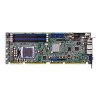
IEI Technology PCIE-Q370 User Manual (140 pages)
Brand:
IEI Technology
| Category:
Desktop
| Size: 3 MB
Table of Contents
Table of Contents
5
1 Introduction
15
Figure 1-1: PCIE-Q370
16
Figure 1-2: Connectors
18
Figure 1-3: PCIE-Q370 Dimensions (MM)
19
Data Flow
20
Figure 1-4: Data Flow Diagram
20
Technical Specifications
21
Dimensions
19
Introduction
16
Features
17
Connectors
18
Table 1-1: PCIE-Q370 Specifications
23
2 Packing List
24
Anti-Static Precautions
25
Unpacking Precautions
25
Packing List
26
Table 2-1: Packing List
26
Optional Items
27
Table 2-2: Optional Items
28
3 Connectors
29
Figure 3-1: Peripheral Interface Connectors
30
Peripheral Interface Connectors
30
PCIE-Q370 Layout
30
Peripheral Interface Connectors
31
External Interface Panel Connectors
32
Internal Peripheral Connectors
32
ATX Power Connector
32
Table 3-2: External Peripheral Connectors
32
Table 3-3: +12V ATX Power Connector Pinouts
33
Battery Connector
34
Table 3-1: Peripheral Interface Connectors
32
Audio Kit Connector
33
Figure 3-2: +12V ATX Power Connector Pinout Location
33
Figure 3-4: Battery Connector Location
35
Figure 3-5: Chassis Intrusion Connector Location
35
Table 3-5: Battery Connector Pinouts
35
Figure 3-6: DDR4 DIMM Socket Locations
36
Figure 3-7: Digital I/O Connector Location
36
EC Debug Connector
37
Figure 3-8: EC Debug Connector Location
37
Table 3-7: Digital I/O Connector Pinouts
37
Fan Connector (CPU)
38
Figure 3-9: CPU Fan Connector Location
38
Table 3-8: EC Debug Connector Pinouts
38
Table 3-9: CPU Fan Connector Pinouts
38
Fan Connectors (System)
39
Figure 3-10: System Fan Connector Location
39
Front Panel Connector
39
Table 3-10: System Fan (SYS_FAN1) Connector Pinouts
39
Figure 3-11: Front Panel Connector Location
40
Figure 3-12: I 2 C Connector Location
40
I 2 C Connector
40
Table 3-11: Front Panel Connector Pinouts
40
Figure 3-13: Keyboard and Mouse Connector Location
41
Keyboard and Mouse Connector
41
Table 3-12: I 2 C Connector Pinouts
41
Figure 3-14: LAN LED Connector Locations
42
LAN LED Connectors
42
Table 3-13: Keyboard and Mouse Connector Pinouts
42
Table 3-14: LAN1 LED Connector (LED_LAN1) Pinouts
42
Table 3-15: LAN2 LED Connector (LED_LAN2) Pinouts
42
2280 Slot, M-Key
43
Figure 3-3: Audio Connector Location
33
Table 3-6: Chassis Intrusion Connector Pinouts
35
DDR4 DIMM Sockets
36
Digital I/O Connector
36
Table 3-4: Audio Connector Pinouts
34
Chassis Intrusion Connector
35
Figure 3-15: M.2 2280 Slot Location
43
Table 3-16: M.2 2280 Connector Pinouts
44
Figure 3-18: RS-422/485 Serial Port Locations
46
RS-422/485 Serial Port
46
Table 3-17: RS-232 Serial Port Pinouts
46
Table 3-18: RS-422/485 Serial Port Pinouts
46
Figure 3-19: SATA 6Gb/S Drive Connector Locations
47
SATA 6Gb/S Drive Connector
47
Table 3-19: DB-9 RS-422/485 Pinouts
47
Figure 3-20: Smbus Connector Location
48
Smbus Connector
48
Table 3-20: SATA 6Gb/S Drive Connector Pinouts
48
Table 3-21: Smbus Connector Pinouts
48
Figure 3-21: SPI Flash Connector Location
49
SPI Flash Connector
49
Table 3-22: SPI Flash Connector Pinouts
49
Figure 3-22: SPI EC Flash Connector Location
50
SPI Flash Connector, EC
50
Table 3-23: SPI EC Flash Connector Pinouts
50
Figure 3-23: TPM Connector Location
51
Table 3-24: TPM Connector Pinouts
51
TPM Connector
51
Figure 3-24: USB 2.0 Connector Locations
52
Table 3-25: USB 2.0 Connector Pinouts
52
USB 2.0 Connectors
52
Figure 3-25: USB 2.0 Connector (Type A) Pinout Location
53
Table 3-26: USB 2.0 Connector (Type A) Pinouts
53
USB 2.0 Connector (Type A)
53
Figure 3-26: USB 3.1 Connector Location
54
Table 3-27: USB 3.1 Connector Pinouts
54
USB 3.1 Connector
54
Ethernet Connectors
55
External Peripheral Interface Connector Panel
55
Table 3-28: LAN Pinouts
55
USB 3.1 Gen 1 Connectors
56
VGA Connector
56
Figure 3-17: RS-232 Serial Port Locations
45
Figure 3-16: Power Button Location
45
Power Button
45
Serial Ports
45
Figure 3-27: External Peripheral Interface Connector
55
Figure 3-28: Ethernet Connector
55
Table 3-29: USB 3.1 Port Pinouts
56
Figure 3-29: VGA Connector
57
Table 3-30: VGA Connector Pinouts
57
4 Installation
58
Anti-Static Precautions
59
Installation Considerations
59
Figure 4-1: Disengage the CPU Socket Load Lever
61
Socket Lga1151 Cpu Installation
61
Figure 4-2: Remove Protective Cover
62
Figure 4-3: Insert the Socket LGA1151 CPU
63
Figure 4-4: Close the Socket LGA1151
63
Figure 4-5: Cooling Kit Support Bracket
65
Figure 4-6: DIMM Installation
66
AT/ATX Power Mode Setting
67
Clear CMOS Button
67
System Configuration
67
DIMM Installation
66
Socket Lga1151 Cooling Kit Installation
64
Figure 4-8: Clear CMOS Button Location
67
Figure 4-7: AT/ATX Power Mode Switch Location
67
Table 4-1: AT/ATX Power Mode Switch Settings
67
Figure 4-9: Flash Descriptor Security Override Jumper Location
68
Flash Descriptor Security Override Jumper
68
Pcie X16 Channel Mode Setup
68
Table 4-3: Flash Descriptor Security Override Jumper Settings
68
Table 4-4: BIOS Options and Configured USB Ports
70
Table 4-5: USB Power Source Setup
70
Figure 4-10: SATA Drive Cable Connection
71
Figure 4-11: SATA Power Drive Connection
72
Driver Download
73
Figure 4-12: IEI Resource Download Center
73
Software Installation
73
Intel ® Amt Setup Procedure
75
USB Power Selection
70
Internal Peripheral Device Connections
71
SATA Drive Connection
71
Table 4-2: Pcie X16 Channel Mode Setup
68
5 Bios
76
Introduction
77
Starting Setup
77
Using Setup
77
Getting Help
78
Unable to Reboot after Configuration Changes
78
BIOS Menu Bar
78
Main
78
Table 5-1: BIOS Navigation Keys
78
BIOS Menu 1: Main
79
Advanced
80
CPU Configuration
81
PCH-FW Configuration
83
Trusted Computing
84
ACPI Settings
85
Iwdd H/W Monitor
86
Smart Fan Mode Configuration
87
F81866 Super IO Configuration
89
Serial Port 1 Configuration
90
Serial Port 2 Configuration
91
Serial Port 3 Configuration
92
Serial Port 4 Configuration
93
RTC Wake Settings
94
Serial Port Console Redirection
95
Legacy Console Redirection Settings
98
USB Configuration
99
CSM Configuration
100
Nvme Configuration
101
Iei Feature
102
Chipset
103
System Agent (SA) Configuration
104
Graphics Configuration
105
Memory Configuration
105
PEG Port Configuration
107
PCH-IO Configuration
108
Table 5-2: BIOS Options and Configured USB Ports
110
PCI Express Configuration
111
SATA Configuration
113
HD Audio Configuration
115
Security
116
Boot
117
Save & Exit
119
A Regulatory Compliance
120
B Product Disposal
122
C Bios Options
124
D Terminology
128
E Digital I/O Interface
132
Introduction
133
Assembly Language Sample 1
134
Assembly Language Sample 2
134
F Watchdog Timer
135
G Hazardous Materials Disclosure
138
Advertisement
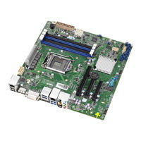
IEI Technology PCIE-Q370 Quick Installation Manual (20 pages)
Brand:
IEI Technology
| Category:
Single board computers
| Size: 0 MB
Advertisement
Related Products
IEI Technology PPC-5150GS
IEI Technology PPC-5xxx-9455
IEI Technology PPC-51xxA-H61
IEI Technology PPC-51 A-H61 Series
IEI Technology PPC-5150AD-H61-i3/R-R10
IEI Technology PPC-5150AD-H61-i5/R-R10
IEI Technology PPC-5170A-H61-i3/R-R10
IEI Technology PPC-5170AD-H61-i3/R-R10
IEI Technology PPC-5170AD-H61-i5/R-R10
IEI Technology PPC-5190A-H61-P/R-R10
IEI Technology Categories
Motherboard
Touch Panel
Computer Hardware
Single board computers
Desktop
More IEI Technology Manuals
Login
Sign In
OR
Sign in with Facebook
Sign in with Google
Upload manual
Upload from disk
Upload from URL