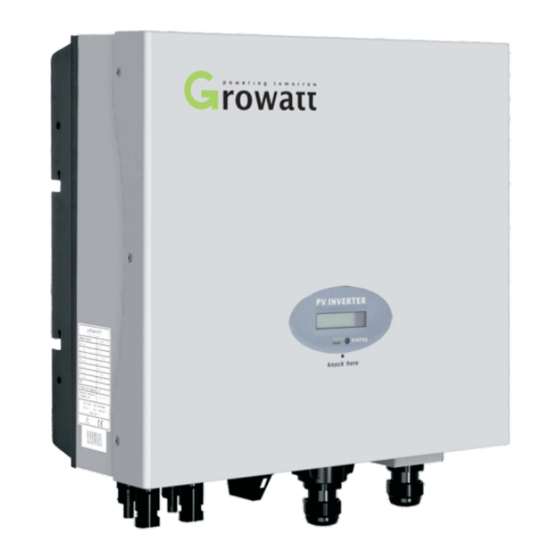
Summary of Contents for Growatt Grid
- Page 1 GROWATT NEW ENERGY CO.,LTD No.28 Guanghui Road, Longteng Community, Shiyan, Baoan District, Shenzhen, P.R. China service@ginverter.com GR - UM - 001 - 09...
-
Page 2: Table Of Contents
Content Design Overview Congratulations on choosing our Grid PV Inverter, Our Grid PV Inverter are a highly reliable products due to their innovative design and perfect quality control. Such inverters are used in high demand, grid-linked PV systems. This manual contains important information regarding installation and safe operation of this unit. - Page 3 Solar inverter This unit is designed to feed power to the public power to the public grid (utility) only. Do not connect this unit to an AC source or Mounting frame generator. Connecting Inverter to external devices could result in serious damage to your equipment.
-
Page 4: Fixed On The Wall
2.3 Connect to the grid (AC utility) Measure the grid (utility) voltage and frequency. It should be 230 VAC (or 220VAC), 50/60Hz and single phase. Open the breaker or fuse between PV Inverter and utility. For Inverter, AC wires specifications as follows:... -
Page 5: Checking
When the PV panels are connected and their output voltage is greater than 70Vdc but the AC grid is not yet connected, inverter will start up automatically. If it is the Single knock on the LCD, countries will vary from one to another along first time to power on the inverter after installation, you may need to select a specific the above list order. -
Page 6: System Diagram
After the inverter reboot, LCD will produce the following messages in order: ‘Ser NO: xxx’->’xxxxx’->’FW version’->’Waiting’->’No AC connection’, the display repeats ’NO Utility’ and LED will be red. Close the AC breaker or fuse between PV-Inverter and grid. Turn on the DC switch. The normal operating sequence begins. Fig 2-5-4 Under normal operating conditions the LCD displays ‘Power: xxx.x W’. -
Page 7: Modes Of Operation
(namely,220_230VAC, 50/60Hz). 3.3 Shutdown mode During periods of little or no sunlight, Inverter automatically stops running. In this mode, Inverter does not take any power from the grid. The display and LED’s on the front panel do not work. Notes Operating inverter is quite easy. -
Page 8: Sound Control Lcd Display
The enable auto test Set Language Set LCD language The First line of LCD Set LCD Contrast Set LCD contrast System F: XXHz The grid frequency DISPLAY STATE REMARK COM address: xx The communication Address 3.4 Sound control LCD display... -
Page 9: Inverter Status
Inverter Status Set the display: Set Queensland grid voltage range Inverter is designed to be user-friendly; therefore, the status of the Inverter can be easily understood by reading the information shown on the front panel display. All possible messages are shown in the following table. -
Page 10: Communications Software Instructions
Communication 5.4 RS 485 cable connection 5.1 Communications software instructions 1. Please take out the RS485 waterproof device from the Accessories bag, even if you don’t choose RS485 as communication method, the RS485 waterproof device still ShineNET is a PC software that communicates with Shine Inverter to analyze the has to be locked on the inverter. - Page 11 Note: 3. Make the cable through the hole of rubber stopper and the RS485 waterproof cover. The type of cable is recommended as “KVVRP22/2*1.5”. ① As to the connection between inverters, please refer to the following figure. 1 2 3 1 2 3 1 2 3 1 2 3...
-
Page 12: Trouble Shooting
Efficiency Max . efficiency Grid Fault Euro-eta 95.5% 95.5% 1. Wait for 5 minutes, if the grid returns to normal, PV-Inverter automatically restarts. MPPT efficiency 99.5% 99.5% 2. Make sure grid voltage and frequency meet the specifications. Protection Devices 3. If the problem persists please call service.


Need help?
Do you have a question about the Grid and is the answer not in the manual?
Questions and answers