Table of Contents
Advertisement
Quick Links
Manual
Pos: 2 /Dokumentation allgemein/Einband/Einband Frontseite - Handbuch; CI 2017; mit DocVariablen (Standard) @ 28\mod_1486477502910_0.docx @ 405388 @ @ 1
WAGO I/O System 750 XTR
750-495/040-010
3-Phase POM 20KV 300A XTR
3-Phase Power Measurement; 20 kV AC; 300 A;
Extreme
(* only in connection with sensors according to section "Measurement of
Voltage, Current and Power")
Version 1.0.0
Pos: 3 /Alle Serien (Allgemeine Module)/Rechtliches, Allgemeines/Impressum für Standardhandbücher - allg. Angaben, Anschriften, Telefonnummern und E-Mail-Adressen @ 3\mod_1219151118203_21.docx @ 21060 @ @ 1
Advertisement
Chapters
Table of Contents

Related Manuals for WAGO I/O System 750 XTR 750-495/040-010


Summary of Contents for WAGO I/O System 750 XTR 750-495/040-010
- Page 1 Manual Pos: 2 /Dokumentation allgemein/Einband/Einband Frontseite - Handbuch; CI 2017; mit DocVariablen (Standard) @ 28\mod_1486477502910_0.docx @ 405388 @ @ 1 WAGO I/O System 750 XTR 750-495/040-010 3-Phase POM 20KV 300A XTR 3-Phase Power Measurement; 20 kV AC; 300 A; Extreme (* only in connection with sensors according to section “Measurement of...
- Page 2 We wish to point out that the software and hardware terms as well as the trademarks of companies used and/or mentioned in the present manual are generally protected by trademark or patent. WAGO is a registered trademark of WAGO Verwaltungsgesellschaft mbH. === Ende der Liste für Textmarke Einband_vorne === Manual...
- Page 3 WAGO I/O System 750 XTR Table of Contents 750-495/040-010 3-Phase POM 20KV 300A XTR Pos: 5 /Dokumentation allgemein/Verzeichnisse/Inhaltsverzeichnis - Überschrift oG und Verzeichnis @ 3\mod_1219151230875_21.docx @ 21063 @ @ 1 Table of Contents Notes about this Documentation .............. 6 Validity of this Documentation ..............6 Revision History ..................
- Page 4 Tabs “Phase L1,” “Phase L2” and “Phase L3” ........91 8.2.3 “Energy” Tab ..................92 8.2.4 “Factory Settings” Tab ............... 94 8.2.5 Displaying the Measured Values with WAGO-I/O-CHECK ....96 8.2.5.1 “Overview” View ................96 8.2.5.2 “Current/Voltages” View ............... 98 8.2.5.3 “Powers”...
- Page 5 WAGO I/O System 750 XTR Table of Contents 750-495/040-010 3-Phase POM 20KV 300A XTR 8.2.5.6 “Measurement Recording” View ..........103 8.2.5.7 “Information” View ..............104 Firmware Update ..................105 Appendix ....................106 10.1 Examples of CSV Files ................ 106 10.1.1 Snapshot ..................
- Page 6 Pos: 9 /Alle Serien (Allgemeine Module)/Überschriften/Ebene 2/Gültigkeitsbereich - Überschrift 2 @ 12\mod_1338912448776_21.docx @ 96469 @ 2 @ 1 Validity of this Documentation Pos: 10 /Serie 750 (WAGO I/O SYSTEM)/Hinweise zur Dokumentation (alte Struktur)/Gültigkeitsbereich/Gültigkeitsbereich Dokumentation I/O-Modul 750-xxxx, ohne Variantenangabe @ 14\mod_1358944037947_21.docx @ 109346 @ @ 1 This documentation is only applicable to the I/O module 750-495/040-010 (3-Phase POM 20KV 300A XTR).
-
Page 7: Table 1: Revision History
Pos: 13 /Alle Serien (Allgemeine Module)/Überschriften/Ebene 2/Änderungshistorie - Überschrift 2 @ 6\mod_1255513312687_21.docx @ 42790 @ 2 @ 1 Revision History Pos: 14 /Serie 750 (WAGO I/O SYSTEM)/Hinweise zur Dokumentation (alte Struktur)/Änderungshistorie/I/O-Module/Änderungshistorie -495/040-010 @ 35\mod_1561045680846_21.docx @ 548579 @ @ 1 Table 1: Revision History... - Page 8 Table of Contents WAGO I/O System 750 XTR 750-495/040-010 3-Phase POM 20KV 300A XTR Pos: 15.4 /Alle Serien (Allgemeine Module)/Überschriften/Ebene 2/Symbole - Überschrift 2 @ 13\mod_1351068042408_21.docx @ 105270 @ 2 @ 1 Symbols Pos: 15.5.1 /Alle Serien (Allgemeine Module)/Sicherheits- und sonstige Hinweise/Gefahr/Gefahr: _Warnung vor Personenschäden allgemein_ - Erläuterung @ 13\mod_1343309450020_21.docx @ 101029 @ @ 1...
-
Page 9: Table 2: Number Notation
WAGO I/O System 750 XTR Table of Contents 750-495/040-010 3-Phase POM 20KV 300A XTR Additional Information: Refers to additional information which is not an integral part of this documentation (e.g., the Internet). Pos: 15.6 /Dokumentation allgemein/Gliederungselemente/---Seitenwechsel--- @ 3\mod_1221108045078_0.docx @ 21810 @ @ 1 Pos: 15.7 /Alle Serien (Allgemeine Module)/Überschriften/Ebene 2/Darstellung der Zahlensysteme - Überschrift 2 @ 23\mod_1435647128078_21.docx @ 184811 @ 2 @ 1... - Page 10 Provisions Pos: 18.6 /Serie 750 (WAGO I/O SYSTEM)/Wichtige Erläuterungen (alte Struktur)/Bestimmungsgemäße Verwendung/Bestimmungsgemäße Verwendung 750- xxxx für Geräte, STD mit EN 61000-6-3 -Verweis auf Geräte-HB @ 3\mod_1224064151234_21.docx @ 24070 @ @ 1 Fieldbus couplers, controllers and I/O modules found in the modular WAGO I/O System 750 receive digital and analog signals from sensors and transmit them to actuators or higher-level control systems.
- Page 11 These modules contain no parts that can be serviced or repaired by the user. The following actions will result in the exclusion of liability on the part of WAGO Kontakttechnik GmbH & Co. KG: •...
- Page 12 Table of Contents WAGO I/O System 750 XTR 750-495/040-010 3-Phase POM 20KV 300A XTR Environmentally friendly disposal benefits health and protects the environment from harmful substances in electrical and electronic equipment. • Observe national and local regulations for the disposal of electrical and electronic equipment.
- Page 13 Pos: 18.14 /Serie 750 (WAGO I/O SYSTEM)/Wichtige Erläuterungen (alte Struktur)/Sicherheits- und sonstige Hinweise/Gefahr/Gefahr: Ausschließlich normgerechte Sensoren einsetzen und technische Daten beachten @ 35\mod_1561660040009_21.docx @ 549369 @ @ 1 Use only standards-compliant sensors, and pay attention to the technical...
- Page 14 Pos: 18.19.1 /Serie 750 (WAGO I/O SYSTEM)/Wichtige Erläuterungen (alte Struktur)/Sicherheits- und sonstige Hinweise/Achtung/Achtung: Einwandfreie Kontaktierung zur Tragschiene gewährleisten! @ 34\mod_1550481407638_21.docx @ 530599 @ @ 1 Ensure proper contact with the DIN-rail! Proper electrical contact between the DIN-rail and device is necessary to maintain the EMC characteristics and function of the device.
- Page 15 WAGO I/O System 750 XTR Table of Contents 750-495/040-010 3-Phase POM 20KV 300A XTR Replace defective or damaged devices! Replace defective or damaged device/module (e.g., in the event of deformed contacts). Pos: 18.19.3 /Alle Serien (Allgemeine Module)/Sicherheits- und sonstige Hinweise/Achtung/Achtung: Geräte vor kriechenden und isolierenden Stoffen schützen! @ 6\mod_1260181036216_21.docx @ 46747 @ @ 1...
- Page 16 I/O module is not approved as a meter for billing purposes in the sense of the electricity metering standard (DIN 43856). Pos: 22 /Serie 750 (WAGO I/O SYSTEM)/Wichtige Erläuterungen (alte Struktur)/Sicherheits- und sonstige Hinweise/Hinweis/Hinweis: Potentialeinspeisemodul einsetzen! (keine LK) @ 3\mod_1226499089640_21.docx @ 25026 @ @ 1 Manual...
- Page 17 Use a power supply module for field-side power supply of downstream I/O modules. Pos: 23 /Serie 750 (WAGO I/O SYSTEM)/Wichtige Erläuterungen (alte Struktur)/Sicherheits- und sonstige Hinweise/Hinweis/Hinweis: XTR - Mischbetrieb XTR/Standard @ 15\mod_1367496420828_21.docx @ 118326 @ @ 1 Mixed operation Mixed operation (standard/XTR modules) within a node is possible when groups of modules are electrically isolated on the field side (i.e., electrically isolated...
-
Page 18: Figure 1: View 750-495/040-010
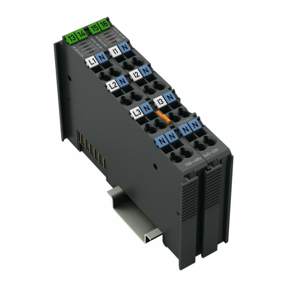
Pos: 27 /Serie 750 (WAGO I/O SYSTEM)/Gerätebeschreibung (alte Struktur)/Ansicht/AI/Ansicht 750-0495/040-010 @ 35\mod_1561045940091_21.docx @ 548587 @ @ 1 Figure 1: View 750-495/040-010 Pos: 28 /Serie 750 (WAGO I/O SYSTEM)/Gerätebeschreibung (alte Struktur)/Ansicht/Ansicht CageClamp®_Legende mit LEDs_ohne Leistungskontakte @ 16\mod_1371816091053_21.docx @ 124052 @ @ 1 Table 4: Legend for Figure “View”... -
Page 19: Figure 2: Data Contacts
Do not place the I/O modules on the gold spring contacts in order to avoid soiling or scratching! Pos: 32.3 /Serie 750 (WAGO I/O SYSTEM)/Wichtige Erläuterungen (alte Struktur)/Sicherheits- und sonstige Hinweise/Achtung/Achtung: ESD - Auf Potentialausgleich der Umgebung achten! @ 32\mod_1539077262331_21.docx @ 504433 @ @ 1 Pay attention to potential equalization from the environment! The devices are equipped with electronic components that may be destroyed by electrostatic discharge. -
Page 20: Figure 3: Cage Clamp ® Connections Of 750-495/040-010
Table of Contents WAGO I/O System 750 XTR 750-495/040-010 3-Phase POM 20KV 300A XTR Pos: 37 /Serie 750 (WAGO I/O SYSTEM)/Gerätebeschreibung (alte Struktur)/Anschlüsse/CAGE CLAMP-Anschlüsse - Überschrift 3 @ 6\mod_1256296337770_21.docx @ 43674 @ 3 @ 1 3.2.3 CAGE CLAMP Connectors ®... -
Page 21: Figure 4: Display Elements
Pos: 40 /Alle Serien (Allgemeine Module)/Überschriften/Ebene 2/Anzeigeelemente - Überschrift 2 @ 4\mod_1240984390875_21.docx @ 31964 @ 2 @ 1 Display Elements Pos: 41 /Serie 750 (WAGO I/O SYSTEM)/Gerätebeschreibung (alte Struktur)/Anzeigeelemente/AI/Anzeigeelemente 750-0495, 750-0495/040-0xx @ 16\mod_1371738731125_21.docx @ 123880 @ @ 1 LED A displays a status message. LEDs B to G display possible error messages. -
Page 22: Figure 5: Fe Spring Contact
Pos: 43 /Alle Serien (Allgemeine Module)/Überschriften/Ebene 2/Bedienelemente - Überschrift 2 @ 4\mod_1239191655456_21.docx @ 30439 @ 2 @ 1 Operating Elements Pos: 44 /Serie 750 (WAGO I/O SYSTEM)/Gerätebeschreibung (alte Struktur)/Bedienelemente/Bedienelemente I/O-Modul 75x-xxxx nicht vorhanden @ 4\mod_1236322031125_21.docx @ 28063 @ @ 1 The I/O module 750-495/040-010 has no operating elements. -
Page 23: Figure 6: Schematic Circuit Diagram For 750-495/040-010
WAGO I/O System 750 XTR Table of Contents 750-495/040-010 3-Phase POM 20KV 300A XTR Figure 6: Schematic Circuit Diagram for 750-495/040-010 Pos: 47 /Dokumentation allgemein/Gliederungselemente/---Seitenwechsel--- @ 3\mod_1221108045078_0.docx @ 21810 @ @ 1 Manual Version 1.0.0... -
Page 24: Table 7: Technical Data - Device
Pos: 48 /Alle Serien (Allgemeine Module)/Überschriften/Ebene 2/Technische Daten - Überschrift 2 @ 3\mod_1232967587687_21.docx @ 26924 @ 2 @ 1 Technical Data Pos: 49.1 /Serie 750 (WAGO I/O SYSTEM)/Gerätebeschreibung (alte Struktur)/Technische Daten/VS (Variablensteuerung)/Technische Daten Gerät (VS) - XTR (mit Überschrift) @ 15\mod_1369311215011_21.docx @ 120260 @ 3 @ 1 3.6.1 Device Data Table 7: Technical Data –... -
Page 25: Table 9: Technical Data - Measurement Inputs
WAGO I/O System 750 XTR Table of Contents 750-495/040-010 3-Phase POM 20KV 300A XTR 3.6.3 Measurement Inputs Table 9: Technical Data – Measurement Inputs Number of inputs 6 (3 voltage measurement inputs and for sensors in medium voltage 3 current measurement inputs with... -
Page 26: Table 12: Technical Data - Measured Values
Device Description WAGO I/O System 750 XTR 750-495/040-010 3-Phase POM 20KV 300A XTR 3.6.4 Measured Values Table 12: Technical Data – Measured Values Measurement method RMS value calculation (true RMS) for voltages and currents, measured value acquisition at 8 kHz, synchronous on... - Page 27 WAGO I/O System 750 XTR Device Description 750-495/040-010 3-Phase POM 20KV 300A XTR Table 12: Technical Data – Measured Values Fundamental vibration/upper harmonic Current 240 ms Voltage 240 ms HD/THD, current 240 ms HD/THD, voltage 240 ms Initialization times: Collection changes Collection 010 approx.
-
Page 28: Table 13: Technical Data - Measurement Accuracy
Input and output data with 128 bits process data and 64 bits control/status each Pos: 49.4 /Serie 750 (WAGO I/O SYSTEM)/Gerätebeschreibung (alte Struktur)/Technische Daten/VS (Variablensteuerung)/Technische Daten Anschlusstechnik (VS) ohne Tabelle LK @ 18\mod_1395045829421_21.docx @ 148018 @ 3 @ 1 3.6.7 Connection Technology Table 15: Technical Data –... -
Page 29: Table 17: Technical Data - Mechanical Conditions
Max. 5g Follow the installation instructions Pos: 49.6 /Serie 750 (WAGO I/O SYSTEM)/Gerätebeschreibung (alte Struktur)/Technische Daten/VS (Variablensteuerung)/Technische Daten klimatische Umweltbedingungen (VS) - XTR - mit Angaben zu Schadstoffen @ 34\mod_1554910084610_21.docx @ 541496 @ 3 @ 1 3.6.9 Climatic Environmental Conditions Table 18: Technical Data ‒... - Page 30 DOWNLOADS Documentation System Description. Pos: 52.2 /Serie 750 (WAGO I/O SYSTEM)/Gerätebeschreibung (alte Struktur)/Zulassungen/Allgemein/Zulassungen I/O-Modul 750-xxxx Allgemein, ohne Variantenangabe - Einleitung @ 4\mod_1237460656921_21.docx @ 28643 @ @ 1 The following approvals have been granted to 750-495/040-010 I/O modules: Pos: 52.3 /Alle Serien (Allgemeine Module)/Zulassungen/Standardzulassungen/CE (Konformitätskennzeichnung) @ 3\mod_1224494777421_21.docx @ 24276 @ @ 1...
-
Page 31: Table 19: Climatic And Mechanical Environmental Conditions And Shipbuilding
750-495/040-010 I/O modules meet the following standards and guidelines: Pos: 56.2 /Serie 750 (WAGO I/O SYSTEM)/Gerätebeschreibung (alte Struktur)/Normen und Richtlinien/Normen und Richtlinien XTR - Mechanik und Klima Komponenten-HB 2017 - ohne Schiffbau @ 37\mod_1600765100003_21.docx @ 594045 @ @ 1 Table 19: Climatic and Mechanical Environmental Conditions and Shipbuilding... -
Page 32: Table 20: Emc - Immunity To Interference
750-495/040-010 3-Phase POM 20KV 300A XTR Pos: 56.4 /Serie 750 (WAGO I/O SYSTEM)/Gerätebeschreibung (alte Struktur)/Normen und Richtlinien/EMV-Normen I/O-Modul 750-xxxx/0040-0000, nur Standardversion - Einleitung XTR @ 18\mod_1395909426189_21.docx @ 149708 @ @ 1 The I/O module 750-495/040-010 meets the following EMC standards as these standards relate to the I/O module: Pos: 56.5 /Serie 750 (WAGO I/O SYSTEM)/Gerätebeschreibung (alte Struktur)/Normen und Richtlinien/Normen Störfestigkeit XTR (Bundle 1-3) - ohne Schiffbau @ 37\mod_1600765384731_21.docx @ 594609 @ @ 1... - Page 33 1 % for 100th to 200th harmonic *) The list of ship certifications issued is available in the section “Approvals”. Pos: null /Serie 750 (WAGO I/O SYSTEM)/Gerätebeschreibung (alte Struktur)/Normen und Richtlinien/Normen Störaussendung XTR - ohne Schiffbau @ 37\mod_1602172273388_21.docx @ 596110 @ @ 1 Manual...
-
Page 34: Table 21: Emc - Emission Of Interference
Device Description WAGO I/O System 750 XTR 750-495/040-010 3-Phase POM 20KV 300A XTR Table 21: EMC – Emission of Interference Standard Test Value Enclosure Emission of Interference • EN 61000-6-3 30 dB(µV/m), QP, 30 MHz … 230 MHz • EN 55032 Class B 37 dB(µV/m), QP, 230 MHz …... - Page 35 Pos: 58 /Alle Serien (Allgemeine Module)/Überschriften/Ebene 1/Funktionsbeschreibung - Überschrift 1 @ 4\mod_1239025975389_21.docx @ 30003 @ 1 @ 1 Function Description Pos: 59.1 /Serie 750 (WAGO I/O SYSTEM)/Funktionsbeschreibung/Funktionsbeschreibung 750-0495/040-010 - Messprinzip, Messwerteübersicht @ 35\mod_1561046761367_21.docx @ 548624 @ 222 @ 1 Measurement Principle...
- Page 36 Function Description WAGO I/O System 750 XTR 750-495/040-010 3-Phase POM 20KV 300A XTR Energy: • Active energy, Lx • Active energy import, Lx • Active energy export, Lx • Active energy, total • Active energy import, total • Active energy export, total •...
- Page 37 Limiting value: • Undervoltage, Lx • Overvoltage, Lx • Overcurrent, Lx The following values are shown only in WAGO-I/O-CHECK and in CODESYS function blocks, not in the process image: - Active power, total - Reactive power, total - Apparent power, total...
-
Page 38: Figure 7: Rms Calculation (Example - Not To Scale)
RMS values. The time interval for which the mean value should be calculated can be set via WAGO-I/O-CHECK or parameters 34, 35 and 36. The minimum and maximum RMS values for the current and voltage are also determined over a configurable time interval (WAGO-I/O-CHECK or parameters 37, 38 and 39). -
Page 39: Figure 8: Assignment Of Active And Reactive Energy In The 4 Quadrants
750-495/040-010 3-Phase POM 20KV 300A XTR Active power minimum and maximum values are determined over a configurable time interval (WAGO-I/O-CHECK or parameters 37, 38 and 39). In real networks, not all loads are purely resistive. Phase shifting occurs between the current and voltage. However, this does not affect the method for determining the RMS values for current and voltage previously described. - Page 40 The representation of the energy values can be scaled by a factor in the process image (PI). This factor can be set by the user in accordance with the application being used (WAGO-I/O-CHECK or register 35) and can be changed at any time. The 2 examples below illustrate the information required for this:...
- Page 41 WAGO I/O System 750 XTR Function Description 750-495/040-010 3-Phase POM 20KV 300A XTR Harmonic analysis Meaning of “upper harmonic” “First harmonic” refers to the vibration at the fundamental frequency (fundamental component), and “first upper harmonic” refers the vibration at twice the fundamental frequency.
-
Page 42: Figure 9: 4-Quadrant Representation For Active And Reactive Power
The 4-quadrant representation has the following form: Figure 9: 4-Quadrant Representation for Active and Reactive Power The 4-quadrant representation is also shown in WAGO-I/O-CHECK for the “Overview,” “Phase, Lx” and “Power” measured value views in the “3-Phase Power Measurement Module” dialog field. -
Page 43: Figure 10: Input Limiting (Clipping)
I/O-CHECK or registers 36, 37 and 38 and parameters 12, 13, 14 and 23 … 31). Signaling is carried out in the process image (PI). Pos: 59.2 /Serie 750 (WAGO I/O SYSTEM)/Funktionsbeschreibung/Funktionsbeschreibung 750-0495/040-010 - Messfehler @ 35\mod_1561046831647_21.docx @ 548631 @ 2 @ 1 Measurement Errors The measurement accuracy of the I/O module is described in section “Device... - Page 44 Function Description WAGO I/O System 750 XTR 750-495/040-010 3-Phase POM 20KV 300A XTR In the event of input overloading of the current or voltage measurement inputs, the I/O module cannot digitize these values and limits the measured values to the maximum measurable range (clipping of the current or voltage measured values).
- Page 45 WAGO I/O System 750 XTR Function Description 750-495/040-010 3-Phase POM 20KV 300A XTR Harmonic analysis The upper harmonic components are determined on the basis of a number of individual values measured within the current curve shapes for voltage and current. From these, the included components of the current fundamental frequency (45 Hz to 65 Hz) and its integer harmonics are calculated.
- Page 46 Pos: 61 /Alle Serien (Allgemeine Module)/Überschriften/Ebene 1/Prozessabbild - Überschrift 1 @ 4\mod_1240983067828_21.docx @ 31942 @ 1 @ 1 Process Image Pos: 62 /Serie 750 (WAGO I/O SYSTEM)/Prozessabbild Lokalbus/AI/Prozessabbild 750-0495/040-010 Teil 1 @ 35\mod_1561046954670_21.docx @ 548639 @ 22332332333 @ 1 The I/O module provides the fieldbus coupler/controller 24 bytes of input and output process data via one logical channel.
-
Page 47: Table Of Contents
WAGO I/O System 750 XTR Process Image 750-495/040-010 3-Phase POM 20KV 300A XTR Overview of the Process Data Table 22: Output and Input Data Byte Output Data Input Data Control word Status word Expanded control word 1 Expanded status word 1... -
Page 48: Control Word
Process Image WAGO I/O System 750 XTR 750-495/040-010 3-Phase POM 20KV 300A XTR Output Data The output data is transmitted from the fieldbus coupler/controller to the I/O module. This data consists of 4 control words and eight data words. 5.2.1... -
Page 49: Expanded Control Word 2
WAGO I/O System 750 XTR Process Image 750-495/040-010 3-Phase POM 20KV 300A XTR Expanded control word 2 Byte 4 Bit 7 Bit 6 Bit 5 Bit 4 Bit 3 2 bit Bit 1 Bit 0 MET_ID_1 MET_ID_1 ID for selection of the measured value from the collection... -
Page 50: Input Data
Process Image WAGO I/O System 750 XTR 750-495/040-010 3-Phase POM 20KV 300A XTR Input Data The input data is transmitted from the I/O module to the fieldbus coupler/controller. This data consists of 4 status words and eight data words (process values 1 … 4). - Page 51 WAGO I/O System 750 XTR Process Image 750-495/040-010 3-Phase POM 20KV 300A XTR Byte 1 Bit 7 Bit 6 Bit 5 Bit 4 Bit 3 2 bit Bit 1 Bit 0 WARN OVER_1 OVER_2 OVER_3 OVER_4 STAT_SEL WARN Warning: Transient reaction measured value collection...
-
Page 52: Expanded Status Word 1
Process Image WAGO I/O System 750 XTR 750-495/040-010 3-Phase POM 20KV 300A XTR Expanded status word 1 Byte 2 Bit 7 Bit 6 Bit 5 Bit 4 Bit 3 Bit 2 Bit 1 Bit 0 STAT7 STAT6 STAT5 STAT4 STAT3... - Page 53 WAGO I/O System 750 XTR Process Image 750-495/040-010 3-Phase POM 20KV 300A XTR STAT1 If STAT_SEL = status of Lx = L1 / L2 / L3: - Underrun of the ZC limit at Lx: 0 = OK 1 = greater measurement error due to...
- Page 54 Process Image WAGO I/O System 750 XTR 750-495/040-010 3-Phase POM 20KV 300A XTR Expanded status word 2 Byte 4 Bit 7 Bit 6 Bit 5 Bit 4 Bit 3 Bit 2 Bit 1 Bit 0 MET_ID_1_SEL MET_ID_1_SEL ID of the measured value from the collection COL_ID_SEL which is in process value 1 of the input data.
- Page 55 WAGO I/O System 750 XTR Process Image 750-495/040-010 3-Phase POM 20KV 300A XTR 5.3.2 Definition of the Input Data Words Process value 1 Byte 8 Bit 7 Bit 6 Bit 5 Bit 4 Bit 3 Bit 2 Bit 1 Bit 0...
- Page 56 Process Image WAGO I/O System 750 XTR 750-495/040-010 3-Phase POM 20KV 300A XTR Process value 2 Byte 12 Bit 7 Bit 6 Bit 5 Bit 4 Bit 3 Bit 2 Bit 1 Bit 0 PROC2[7:0] PROC2[7:0] Byte of the measured value with the MET_ID “MET_ID_2_SEL”...
- Page 57 WAGO I/O System 750 XTR Process Image 750-495/040-010 3-Phase POM 20KV 300A XTR Process value 3 Byte 16 Bit 7 Bit 6 Bit 5 Bit 4 Bit 3 Bit 2 Bit 1 Bit 0 PROC3[7:0] PROC3[7:0] Byte of the measured value with the MET_ID “MET_ID_3_SEL”...
- Page 58 Process Image WAGO I/O System 750 XTR 750-495/040-010 3-Phase POM 20KV 300A XTR Process value 4 Byte 20 Bit 7 Bit 6 Bit 5 Bit 4 Bit 3 Bit 2 Bit 1 Bit 0 PROC4[7:0] PROC4[7:0] Byte of the measured value with the MET_ID “MET_ID_4_SEL”...
- Page 59 WAGO I/O System 750 XTR Process Image 750-495/040-010 3-Phase POM 20KV 300A XTR Descriptions for the Process Image The I/O module provides a large number of measured values for a 3-phase power supply system. These measured values are organized into collections which can be selected by specifying the COL_ID.
- Page 60 Process Image WAGO I/O System 750 XTR 750-495/040-010 3-Phase POM 20KV 300A XTR 5.4.1 AC Measured Value Collection (010) In the output data of the I/O module, the collection is selected via the COL_ID, and 4 different measured values are selected from this collection via the MET_IDs.
- Page 61 WAGO I/O System 750 XTR Process Image 750-495/040-010 3-Phase POM 20KV 300A XTR 5.4.2 Harmonic Analysis Collections (020, 021, 022) In the I/O module output data, the corresponding harmonic analysis collection is selected and the MET_IDs are set. These measured values are then made available in the input data.
- Page 62 Process Image WAGO I/O System 750 XTR 750-495/040-010 3-Phase POM 20KV 300A XTR – 1nd upper harmonic, L1 [7:0] – 1nd upper harmonic, L1 [15:8] – 1nd upper harmonic, L1 [23:16] – 1nd upper harmonic, L1 [31:24] – 2nd upper harmonic, L1 [7:0] –...
- Page 63 WAGO I/O System 750 XTR Process Image 750-495/040-010 3-Phase POM 20KV 300A XTR A status query was also set in the examples given here. In example 1, the status query is performed for the I/O module. The status word (byte 0) is at 0x48; an error has occurred in the I/O module (ERROR, ERR_BK).
-
Page 64: Table 23: Pi Data Type - Definition
WAGO I/O System 750 XTR 750-495/040-010 3-Phase POM 20KV 300A XTR Pos: 64 /Serie 750 (WAGO I/O SYSTEM)/Prozessabbild Lokalbus/AI/Prozessabbild 750-0495/040-010 Teil 2 @ 35\mod_1561047025168_21.docx @ 548654 @ 2332 @ 1 Measured Value Collections The PI data type is either an unsigned (UInt32) or a signed (Int32) 32-bit measured value. - Page 65 WAGO I/O System 750 XTR Process Image 750-495/040-010 3-Phase POM 20KV 300A XTR Current RMS current, L1 UInt32 0.0001 A RMS current, L2 UInt32 0.0001 A RMS current, L3 UInt32 0.0001 A Max. RMS current, L1 UInt32 0.0001 A Max. RMS current, L2 UInt32 0.0001 A...
- Page 66 Process Image WAGO I/O System 750 XTR 750-495/040-010 3-Phase POM 20KV 300A XTR Energy Active energy, L1 Int32 Active energy, L2 Int32 Active energy, L3 Int32 Active energy import, L1 UInt32 Active energy import, L2 UInt32 Active energy import, L3...
- Page 67 WAGO I/O System 750 XTR Process Image 750-495/040-010 3-Phase POM 20KV 300A XTR Phase angle phi Phase angle phi, L1 UInt32 0.01 degrees Phase angle phi, L2 UInt32 0.01 degrees Phase angle phi, L3 UInt32 0.01 degrees cos phi, L1 Int32 0.01...
-
Page 68: Table 25: Measured Values Of Collections 020, 021 And 022 In The Process
Process Image WAGO I/O System 750 XTR 750-495/040-010 3-Phase POM 20KV 300A XTR 5.5.2 Collections 020, 021 and 022 – Harmonic Analysis Note Wait for end of initialization time The selected measured values of the collection stabilize after about 1100 ms. - Page 69 WAGO I/O System 750 XTR Process Image 750-495/040-010 3-Phase POM 20KV 300A XTR Examples of the Calculation of the Measured Values from the Process Values The format of signed measured values (Int32) is the two’s complement. In general, the following formula applies to the calculation of the measured values from the process values: Measured value = process value ×...
- Page 70 Process Image WAGO I/O System 750 XTR 750-495/040-010 3-Phase POM 20KV 300A XTR Calculation of the Current-Dependent Measured Values (Current, Power and Energy) Overvoltage Threshold L1 Process value 0x002DC6C0 (3,000,000) PI Scaling Factor 0.0001 A Formula Measured value = process value × PI scaling...
- Page 71 Do not touch the blade contacts. Pos: 70 /Serie 750 (WAGO I/O SYSTEM)/Wichtige Erläuterungen (alte Struktur)/Sicherheits- und sonstige Hinweise/Achtung/Achtung: I/O-Module nur in vorgesehener Reihenfolge stecken! @ 6\mod_1256194177073_21.docx @ 43429 @ @ 1 Insert I/O modules only from the proper direction! All I/O modules feature grooves for power jumper contacts on the right side.
- Page 72 I/O modules with power contacts (blade contacts) cannot be linked to I/O modules with fewer power contacts. Pos: 73 /Serie 750 (WAGO I/O SYSTEM)/Montieren/Demontieren/I/O-Module 750xxxx/0040xxxx 4g-5g @ 15\mod_1367558844291_21.docx @ 118470 @ @ 1 For vibration loads > 4g, observe the following installation instructions: •...
-
Page 73: Figure 11: Inserting I/O Module (Example)
Pos: 78 /Serie 750 (WAGO I/O SYSTEM)/Wichtige Erläuterungen (alte Struktur)/Sicherheits- und sonstige Hinweise/Achtung/Achtung: XTR nicht unter -20 °C verdrahten oder umstecken @ 15\mod_1367559895186_21.docx @ 118480 @ @ 1 Temperature range applies to normal operation! XTR I/O modules may be operated below −20 °C, but not wired and/or... -
Page 74: Figure 12: Snap The I/O Module Into Place (Example)
(if any) to the head station or to the preceding and, if applicable, following I/O module are established. Pos: 80 /Serie 750 (WAGO I/O SYSTEM)/Montieren/Demontieren/I/O-Modul entfernen (neutrales 3D) @ 35\mod_1561382848176_21.docx @ 548874 @ 3 @ 1 6.2.2 Removing the I/O Module Remove the I/O module from the assembly by pulling the release tab. - Page 75 Pos: 82 /Alle Serien (Allgemeine Module)/Überschriften/Ebene 1/Geräte anschließen - Überschrift 1 @ 3\mod_1234172889468_21.docx @ 27460 @ 1 @ 1 Connect Devices Pos: 83 /Serie 750 (WAGO I/O SYSTEM)/Anschließen/Schutz vor gefährlichen Berührungsspannungen 750-0495/040-010 @ 35\mod_1561659122511_21.docx @ 549353 @ 2 @ 1 Protection against Hazardous Touch Voltages...
-
Page 76: Figure 14: Cable Shield At Ground Potential
Connect Devices WAGO I/O System 750 XTR 750-495/040-010 3-Phase POM 20KV 300A XTR Pos: 85 /Serie 750 (WAGO I/O SYSTEM)/Systembeschreibung/Versorgung/Schirmung 750-495/040-001 @ 37\mod_1596793098699_21.docx @ 587433 @ 2333 @ 1 Shielding 7.2.1 General Use of shielded cables reduces electromagnetic interference and thus increases signal quality. - Page 77 I/O module can be achieved even in the presence of interference acting on the signal cable. On some WAGO devices you can directly clamp the shield. For all other devices use the WAGO shield connecting system.
-
Page 78: Figure 15: Connecting A Conductor To A Cage Clamp
WAGO I/O System 750 XTR 750-495/040-010 3-Phase POM 20KV 300A XTR Pos: 87 /Serie 750 (WAGO I/O SYSTEM)/Anschließen/Leiter an CAGE CLAMP anschließen (allgemein) - Überschrift 2 und Text @ 3\mod_1225448660171_21.docx @ 24928 @ 2 @ 1 Connecting a Conductor to the CAGE CLAMP ®... - Page 79 Connect Devices 750-495/040-010 3-Phase POM 20KV 300A XTR Pos: 89 /Serie 750 (WAGO I/O SYSTEM)/Anschließen/Anschlussbeispiele/Analogeingänge/Leistungs-, Spannungs-, Strommessung 750-0495/040-010 @ 35\mod_1561047364614_21.docx @ 548662 @ 2 @ 1 Measurement of Voltage, Current and Power Use only standards-compliant sensors, and pay attention to the technical...
-
Page 80: Figure 16: Connection Schematic For Voltage And Current Measurement
Connect Devices WAGO I/O System 750 XTR 750-495/040-010 3-Phase POM 20KV 300A XTR Twelve CAGE CLAMP connections are used for power measurement. ® Figure 16: Connection Schematic for Voltage and Current Measurement Using Voltage/Current Sensors Table 26: Legend for Figure “Connection Schematic for Voltage and Current Measurement Using Voltage/Current Sensors”... - Page 81 Pos: 91 /Alle Serien (Allgemeine Module)/Überschriften/Ebene 1/In Betrieb nehmen - Überschrift 1 @ 4\mod_1240901452750_21.docx @ 31570 @ 1 @ 1 Commissioning Pos: 92 /Serie 750 (WAGO I/O SYSTEM)/In Betrieb nehmen/Parametrieren mit WAGO-I/O-CHECK/Parametrieren mit WAGO-I/O-CHECK, allgemein 750-0495/040-010 @ 35\mod_1561048255142_21.docx @ 548716 @ 2333333 @ 1 General The I/O module that is latched into the node and connected for measurement can now be put into operation using the WAGO-I/O-CHECK software for Windows.
-
Page 82: Figure 17: Wago-I/O-Check User Interface, Node With I/O Module
To display the node on the PC, connect both using the USB communication cable and launch WAGO-I/O-CHECK. The node is displayed. Figure 17: WAGO-I/O-CHECK User Interface, Node with I/O Module (Example) Right-click on the picture of the I/O module and select the [Settings] menu item. The “3-Phase Power Measurement Module” dialog opens: Manual Version 1.0.0... -
Page 83: Figure 18: "3-Phase Power Measurement Module" Dialog
WAGO I/O System 750 XTR Commissioning 750-495/040-010 3-Phase POM 20KV 300A XTR The dialog appears: Figure 18: “3-Phase Power Measurement Module” Dialog The dialog contains the following sections: “Start” ribbon (1) - “Measured Value Views” menu (2) - Status bar (3) The individual sections are described below. - Page 84 (3) as a CSV file. In this window, enter a file name and select the storage location. See the section “Appendix” for examples. [Settings] Opens the settings dialog [Calibration] Opens the calibration dialog. WAGO Support can provide more information. [Units] Opens a drop-down list of measuring units. 8.1.3 “Measured Value Views” Menu In the “Measured Value Views”...
- Page 85 WAGO I/O System 750 XTR Commissioning 750-495/040-010 3-Phase POM 20KV 300A XTR 8.1.4 Status Bar The following information is displayed in the status bar: - Connection status of the I/O module - IP address of the fieldbus coupler/controller or name of the COM port...
-
Page 86: Figure 19: "Settings" Dialog
Commissioning WAGO I/O System 750 XTR 750-495/040-010 3-Phase POM 20KV 300A XTR 8.1.5 “Settings” Dialog In the “Settings” dialog, you can adjust the user settings and I/O module parameters. To open the dialog, click [Settings] in the Start ribbon (1). - Page 87 WAGO I/O System 750 XTR Commissioning 750-495/040-010 3-Phase POM 20KV 300A XTR The main menu (1) offers the following tabs: - Module - Phase L1 - Phase L2 - Phase L3 - Energy - Factory Settings You can find more information on this in section “Settings and Measured Values ...”...
-
Page 88: Figure 20: Changing The Measurement Units
Commissioning WAGO I/O System 750 XTR 750-495/040-010 3-Phase POM 20KV 300A XTR 8.1.6 Setting Measurement Units For displaying the various measured values, you can choose between different decimal prefixes for the measurement units: - 10 = milli −3 - 10... - Page 89 WAGO I/O System 750 XTR Commissioning 750-495/040-010 3-Phase POM 20KV 300A XTR Pos: 94 /Serie 750 (WAGO I/O SYSTEM)/In Betrieb nehmen/Parametrieren mit WAGO-I/O-CHECK/Parametrieren mit WAGO-I/O-CHECK, 750-0495/040-010 @ 35\mod_1563976107408_21.docx @ 555347 @ 23333 @ 1 Settings and Measured Values 8.2.1 “I/O Module” Tab On the “I/O Module”...
-
Page 90: Figure 21: "Module" Tab
Commissioning WAGO I/O System 750 XTR 750-495/040-010 3-Phase POM 20KV 300A XTR Figure 21: “Module” Tab Manual Version 1.0.0... -
Page 91: Figure 22: "Phase L1" Tab
WAGO I/O System 750 XTR Commissioning 750-495/040-010 3-Phase POM 20KV 300A XTR 8.2.2 Tabs “Phase L1,” “Phase L2” and “Phase L3” Use the "Phase L1," "Phase L2" and "Phase L3" tabs to configure minimum/maximum values and general parameters. These settings are saved to the I/O module. - Page 92 On the “Energy” tab, you can adjust or reset the energy values for each phase after entering the password. The initial password is “wago”. After the first use, please change this password using [Change password]. If you have forgotten the password, you can uninstall and reinstall the plug-in for the 3-Phase Power Measurement Module.
-
Page 93: Figure 23: "Energy" Tab
WAGO I/O System 750 XTR Commissioning 750-495/040-010 3-Phase POM 20KV 300A XTR Figure 23: “Energy” Tab Manual Version 1.0.0... - Page 94 On the “Factory Settings” tab, you can reset all parameters of the I/O module to the factory settings after entering the password. The initial password is “wago”. After the first use, please change this password using [Change password]. If you have forgotten the password, you can uninstall and reinstall the plug-in for the 3-Phase Power Measurement Module.
-
Page 95: Figure 24: "Factory Settings" Tab
WAGO I/O System 750 XTR Commissioning 750-495/040-010 3-Phase POM 20KV 300A XTR Figure 24: “Factory Settings” Tab Pos: 95 /Dokumentation allgemein/Gliederungselemente/---Seitenwechsel--- @ 3\mod_1221108045078_0.docx @ 21810 @ @ 1 Manual Version 1.0.0... -
Page 96: Figure 25: Measured Values - Overview
WAGO I/O System 750 XTR 750-495/040-010 3-Phase POM 20KV 300A XTR Pos: 96 /Serie 750 (WAGO I/O SYSTEM)/In Betrieb nehmen/Anzeigen der Messwerte mit WAGO-I/O-CHECK 750-0495/040-010 @ 35\mod_1561048347415_21.docx @ 548727 @ 344444444 @ 1 8.2.5 Displaying the Measured Values with WAGO-I/O-CHECK 8.2.5.1... -
Page 97: Figure 26: Measured Values - Phases
WAGO I/O System 750 XTR Commissioning 750-495/040-010 3-Phase POM 20KV 300A XTR “Phase L1/L2/L3 Measured Values” View The “Phase L1/L2/L3 Measured Values” view offers detailed displays of the measured values of the corresponding phase, including minimum, maximum, average and peak values. -
Page 98: Figure 27: Measured Values - Currents And Voltages
Commissioning WAGO I/O System 750 XTR 750-495/040-010 3-Phase POM 20KV 300A XTR However the peak values are only displayed if this phase was selected for peak value measurement. See section “Configuration with WAGO-I/O-CHECK” > “‘I/O Module’ Tab.” 8.2.5.2 “Current/Voltages” View The “Currents/Voltages”... -
Page 99: Figure 28: Measured Values - Powers
WAGO I/O System 750 XTR Commissioning 750-495/040-010 3-Phase POM 20KV 300A XTR 8.2.5.3 “Powers” View The “Powers” view shows the active, reactive and apparent power of all 3 phases, the minimum and maximum values for active power, the power factors and the 4-quadrant displays: •... -
Page 100: Figure 29: Measured Values - Energies
100 Commissioning WAGO I/O System 750 XTR 750-495/040-010 3-Phase POM 20KV 300A XTR 8.2.5.4 “Energies” View For all 3 phases, the “Energies” view shows the active energy values with import and export, the reactive energy values with the inductive and capacitive portions... -
Page 101: Figure 30: Measured Values - Upper Harmonics Diagram
WAGO I/O System 750 XTR Commissioning 101 750-495/040-010 3-Phase POM 20KV 300A XTR 8.2.5.5 “Upper Harmonics” View The “Upper Harmonics” view provides both a graphical and a tabular overview of the 40 upper harmonics of the 3 phases. When this view is selected, the “Analysis” context tab (next to “Start”) opens;... -
Page 102: Figure 31: Measured Values - Upper Harmonics Table
102 Commissioning WAGO I/O System 750 XTR 750-495/040-010 3-Phase POM 20KV 300A XTR For the fundamental component (1st harmonic) and 3 selectable upper harmonics of the selected phase, the Table View displays: • Current • Harmonic distortion – THD and HD, current •... -
Page 103: Figure 32: Measured Values - Measurement Recording
WAGO I/O System 750 XTR Commissioning 103 750-495/040-010 3-Phase POM 20KV 300A XTR 8.2.5.6 “Measurement Recording” View The “Measurement Recording” view shows the progression over time of 3 measured quantities. Select the measured quantities to display from the corresponding selection list. -
Page 104: Figure 33: Measured Values - Information
104 Commissioning WAGO I/O System 750 XTR 750-495/040-010 3-Phase POM 20KV 300A XTR 8.2.5.7 “Information” View The “Information” view shows the item number, the designation of the I/O module, the number of the firmware version (“software version”) and the number of the hardware version. - Page 105 Pos: 98 /Alle Serien (Allgemeine Module)/Überschriften/Ebene 1/Firmware-Update - Überschrift 1 @ 32\mod_1532614793963_21.docx @ 492113 @ 1 @ 1 Firmware Update Pos: 99 /Serie 750 (WAGO I/O SYSTEM)/Service/Firmware-Änderung/750-495/040-010 - Service - Firmware-Update @ 35\mod_1561047723973_21.docx @ 548694 @ @ 1 You can update the firmware on the Series 750 I/O modules with the “WAGO I/O Update 750”...
- Page 106 Pos: 101 /Alle Serien (Allgemeine Module)/Überschriften/Ebene 1/Anhang - Überschrift 1 @ 4\mod_1239874070437_21.docx @ 30560 @ 1 @ 1 Appendix Pos: 102 /Serie 750 (WAGO I/O SYSTEM)/Anhang/Beispiele für CSV-Dateien 750-495/040-010 @ 35\mod_1561047850652_21.docx @ 548698 @ 233 @ 1 10.1 Examples of CSV Files 10.1.1...
- Page 107 WAGO I/O System 750 XTR Appendix 107 750-495/040-010 3-Phase POM 20KV 300A XTR Table 27: CSV File “Snapshot” I/O-Check 3-Phase Power Measurement cos phi, L1 0.99 cos phi, L2 0.99 cos phi, L3 0.99 PF power factor, L1 0.99 PF power factor, L2 0.99...
- Page 108 108 Appendix WAGO I/O System 750 XTR 750-495/040-010 3-Phase POM 20KV 300A XTR Table 27: CSV File “Snapshot” I/O-Check 3-Phase Power Measurement Active energy, L3 7083200 Wh Active energy import, L1 7506800 Wh Active energy import, L2 7074000 Wh Active energy import, L3...
-
Page 109: Table 27: Csv File "Snapshot
WAGO I/O System 750 XTR Appendix 109 750-495/040-010 3-Phase POM 20KV 300A XTR Table 27: CSV File “Snapshot” I/O-Check 3-Phase Power Measurement Errors/Warnings I/O Module Parameters Watchdog process data communication False active Nominal frequency 50 Hz Scaling factor, energy values 0.1 kWh/kvarh/kVAh... - Page 110 110 Appendix WAGO I/O System 750 XTR 750-495/040-010 3-Phase POM 20KV 300A XTR Table 27: CSV File “Snapshot” I/O-Check 3-Phase Power Measurement Parameters, Phase L3 Overvoltage limit 2100 V Overcurrent limit 5000 A Interval observation: 60 s arithm. mean calculation...
-
Page 111: Table 28: Csv File "Measurement Recording" (Example)
750-495/040-010 3-Phase POM 20KV 300A XTR 10.1.2 Measurement Recording The following table provides an example of a CSV file generated with WAGO-I/O- CHECK in the “3-Phase Power Measurement Module” dialog on the Measurement Recording page with [Start]. In this case, the variable “Voltage (rms), L1-N”... -
Page 112: Table 29: Factory Settings - Registers
Pos: 104 /Alle Serien (Allgemeine Module)/Überschriften/Ebene 2/Werkseinstellungen - Überschrift 2 @ 15\mod_1366373603819_21.docx @ 117430 @ 2 @ 1 10.2 Factory Settings Pos: 105 /Serie 750 (WAGO I/O SYSTEM)/Anhang/Werkseinstellungen (Default) 750-495/040-010 @ 35\mod_1561047932896_21.docx @ 548705 @ @ 1 The following values in the registers and parameters are factory settings: Table 29: Factory Settings – Registers R32 ≙... -
Page 113: Table 30: Factory Settings - Parameters
WAGO I/O System 750 XTR Appendix 113 750-495/040-010 3-Phase POM 20KV 300A XTR Table 30: Factory Settings – Parameters P10 ≙ R32 0x0000 ≙ 0 Parameters Factory Settings (Default Value) P11 ≙ R35 0x0006 ≙ 1 kWh/kVARh/kVAh P12 ≙ R36 0x0000 ≙... -
Page 114: Table 31: Register 4
114 Appendix WAGO I/O System 750 XTR 750-495/040-010 3-Phase POM 20KV 300A XTR Pos: 107 /Serie 750 (WAGO I/O SYSTEM)/In Betrieb nehmen/Parametrieren über Registerkommunikation/Registerbelegung und Parameterbel. 750-495/040-010 @ 35\mod_1561048044266_21.docx @ 548709 @ 22 @ 1 10.3 Register Assignment The tables below show the assignments and factory settings for the registers written during parameterization and during operation. -
Page 115: Table 32: Register 5
WAGO I/O System 750 XTR Appendix 115 750-495/040-010 3-Phase POM 20KV 300A XTR Table 32: Register 5 Register 5 – “Response” Command Interface Function Data Type Access Factory Setting "Response” Command Interface UINT 0x0000 High byte Sequence number (Session ID) -
Page 116: Table 34: Register 35
116 Appendix WAGO I/O System 750 XTR 750-495/040-010 3-Phase POM 20KV 300A XTR Table 33: Register 32 Register 32 – Feature Register Function Data Type Access Factory Setting Feature Register Flags 0x0000 Automatic deletion of minimum and maximum current, voltage and power values is... -
Page 117: Table 38: Register 43
WAGO I/O System 750 XTR Appendix 117 750-495/040-010 3-Phase POM 20KV 300A XTR Table 38: Register 43 Register 43 – Observation Interval, Peak Value Measurement, Phase 1 Function Data Type Access Factory Setting Observation interval, peak value measurement, UINT 0x000A phase 1 0 …... -
Page 118: Table 42: Register 47
118 Appendix WAGO I/O System 750 XTR 750-495/040-010 3-Phase POM 20KV 300A XTR Table 42: Register 47 Register 47 – Error Register for the Parameter Channel Function Data Type Access Factory Setting Error register for the parameter channel UINT 0x0000... -
Page 119: Table 48: Register 53
WAGO I/O System 750 XTR Appendix 119 750-495/040-010 3-Phase POM 20KV 300A XTR Table 48: Register 53 Register 53 – Container 6 Function Data Type Access Factory Setting Container 6, UINT 0x0000 for energy meter and calibration preset Table 49: Register 54 Register 54 –... -
Page 120: Table 51: Register 62
120 Appendix WAGO I/O System 750 XTR 750-495/040-010 3-Phase POM 20KV 300A XTR Table 51: Register 62 Register 62 – Power-On Self-Test Function Data Type Access Factory Setting Power-On Self-Test UINT None Bit 0: -reserved- Bit 1: FLASH checksum error... -
Page 121: Table 52: Parameter 10
WAGO I/O System 750 XTR Appendix 121 750-495/040-010 3-Phase POM 20KV 300A XTR 10.4 Parameter Assignment Table 52: Parameter 10 Parameter 10 – Feature Register Function Data Type Access Factory Setting - Corresponds to register 32 (see section “Register Assignment”) Table 53: Parameter 11 Parameter 11 –... -
Page 122: Table 60: Parameter 22
122 Appendix WAGO I/O System 750 XTR 750-495/040-010 3-Phase POM 20KV 300A XTR Table 60: Parameter 22 Parameter 22 – Storage Interval, Energy Consumption Function Data Type Access Factory Setting - Corresponds to register 46 (see section “Register Assignment”) Table 61: Parameter 23 Parameter 23 –... -
Page 123: Table 66: Parameters 30 And 31
WAGO I/O System 750 XTR Appendix 123 750-495/040-010 3-Phase POM 20KV 300A XTR Table 66: Parameters 30 and 31 Parameters 30 and 31 – Overcurrent Threshold Value, Phase 3 Function Data Type Access Factory Setting Overcurrent threshold value, phase 3... -
Page 124: Table 69: Parameter 36
124 Appendix WAGO I/O System 750 XTR 750-495/040-010 3-Phase POM 20KV 300A XTR Table 69: Parameter 36 Parameter 36 – Observation Interval, Arithmetic Mean Value, Phase 3 Function Data Type Access Factory Setting Observation interval, arithm. Mean value, phase UINT... -
Page 125: Table 73: Parameter 40 (Supported By Firmware Versions 05 And Above)
WAGO I/O System 750 XTR Appendix 125 750-495/040-010 3-Phase POM 20KV 300A XTR Table 73: Parameter 40 (Supported by Firmware Versions 05 and above) Parameter 40 – NOLOAD Threshold, Active Energy Function Data Type Access Factory Setting Active power threshold above which the active... - Page 126 ® Figure 16: Connection Schematic for Voltage and Current Measurement Using Voltage/Current Sensors ..............80 Figure 17: WAGO-I/O-CHECK User Interface, Node with I/O Module (Example) ....................82 Figure 18: “3-Phase Power Measurement Module” Dialog ........83 Figure 19: “Settings” Dialog ................. 86 Figure 20: Changing the Measurement Units ............
- Page 127 WAGO I/O System 750 XTR List of Tables 127 750-495/040-010 3-Phase POM 20KV 300A XTR Pos: 111 /Dokumentation allgemein/Verzeichnisse/Tabellenverzeichnis - Überschrift oG und Verzeichnis @ 3\mod_1219222958703_21.docx @ 21084 @ @ 1 List of Tables Table 1: Revision History ..................7 Table 2: Number Notation ..................
- Page 128 128 List of Tables WAGO I/O System 750 XTR 750-495/040-010 3-Phase POM 20KV 300A XTR Table 46: Register 51 ..................118 Table 47: Register 52 ..................118 Table 48: Register 53 ..................119 Table 49: Register 54 ..................119 Table 50: Register 55 ..................119 Table 51: Register 62 ..................
- Page 129 WAGO I/O System 750 XTR 750-495/040-010 3-Phase POM 20KV 300A XTR Pos: 113 /Dokumentation allgemein/Einband/Einband - Leerseite für durch 2 teilbare Seitenzahl (Standarddruck) @ 3\mod_1219230851078_0.docx @ 21123 @ @ 1 Manual Version 1.0.0...
- Page 130 Pos: 114 /Dokumentation allgemein/Einband/Einband Rückseite - alle Dokumente; CI 2017 @ 28\mod_1486477503580_21.docx @ 405394 @ @ 1 WAGO Kontakttechnik GmbH & Co. KG Postfach 2880 • D - 32385 Minden Hansastraße 27 • D - 32423 Minden Phone: +49 571 887 – 0 Fax: +49 571 887 –...
Need help?
Do you have a question about the I/O System 750 XTR 750-495/040-010 and is the answer not in the manual?
Questions and answers