Sign In
Upload
Manuals
Brands
ADLINK Technology Manuals
Computer Hardware
cPCI-3630 Series
ADLINK Technology cPCI-3630 Series Manuals
Manuals and User Guides for ADLINK Technology cPCI-3630 Series. We have
1
ADLINK Technology cPCI-3630 Series manual available for free PDF download: User Manual
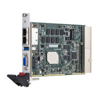
ADLINK Technology cPCI-3630 Series User Manual (103 pages)
Low-Power 3U CompactPCI Quad-Core Intel Atom Processor Blade
Brand:
ADLINK Technology
| Category:
Computer Hardware
| Size: 3 MB
Table of Contents
Preface
3
Table of Contents
5
List of Figures
9
List of Tables
11
1 Introduction
13
Overview
13
Features
14
Model Number Decoder
15
Package Contents
17
2 Specifications
19
Cpci-3630 Processor Blade Specifications
19
Table 2-1: Cpci-3630 Processor Blade Specifications
19
Cpci-R3610(T) RTM Specifications
22
Table 2-2: Cpci-R3610(T) RTM Specifications
22
Block Diagrams
23
Figure 2-1: Cpci-3630 Blade Functional Block Diagram
23
Figure 2-4: Cpci-R3610 RTM Functional Block Diagram
25
I/O Connectivity Table
26
Table 2-3: Cpci-3630 I/O Connectivity
26
Power Requirements
27
3 Functional Description
29
Processors
29
XMC
32
Intel® Virtualization Technology
32
Intel® AES New Instructions
32
Battery
32
4 Board Interfaces
33
Cpci-3630 Series Board Layout
33
Figure 4-1: Cpci-3630 Series Board Layout
33
Cpci-3630 Blade Assembly Layout
34
Figure 4-2: Cpci-3630 Blade Assembly Layout
34
Cpci-3630D Blade Assembly Layout
35
Figure 4-3: Cpci-3630D Blade Assembly Layout
35
Cpci-3630G Blade Assembly Layout
36
Figure 4-4: Cpci-3630G Blade Assembly Layout
36
Cpci-3630M Blade Assembly Layout
37
Figure 4-5: Cpci-3630M Blade Assembly Layout
37
Cpci-3630N Blade Assembly Layout
38
Cpci-3630S Blade Assembly Layout
38
Figure 4-6: Cpci-3630S Blade Assembly Layout
38
Cpci-3630T Blade Assembly Layout
39
Figure 4-7: Cpci-3630T Blade Assembly Layout
39
Cpci-3630TR Blade Assembly Layout
40
Figure 4-8: Cpci-3630TR Blade Assembly Layout
40
Cpci-3630 Series Faceplate
41
Figure 4-9: Cpci-3630, Cpci-3630D/G Faceplate Layout
41
Figure 4-10: Cpci-3630M/N/S Faceplate Layout
42
Figure 4-11: Cpci-3630T(R) Faceplate Layout
43
Table 4-1: Cpci-3630 Faceplate System LED Descriptions
44
Cpci-R3610(T) RTM Board Layout
45
Figure 4-12: Cpci-R3610(T) RTM Board Layout
45
Cpci-R3610(T) RTM Faceplate
46
Figure 4-13: Cpci-R3610(T) RTM Faceplate
46
Cpci-3630 Blade Connector Pin Assignments
47
Table 4-2: USB 2.0 Pin Definition
47
Table 4-3: VGA Pin Definition
48
Table 4-4: PS/2 Keyboard/Mouse Pin Definition
48
Table 4-5: RJ-45 Gbe Pin Definitions
49
Table 4-6: LAN Status LED Definitions
49
Table 4-7: RJ-45 Gbe Pin Definitions
50
Table 4-8: Cpci-3630D/T(R) COM1 (DB-9) Pin Definition
50
Table 4-9: Cpci-3630M 100-Pin I/O Connector Pin Definition
51
Table 4-10: Serial ATA Connector on DB-3610L2 Pin Definition
53
Table 4-11: XMC Connector Pin Definition
54
Table 4-12: Compactpci J1 Connector Pin Definition
55
Table 4-13: Compactpci J2 Connector Pin Definition
56
Cpci-R3610(T) RTM Connector Pin Assignments
58
Table 4-14: Cpci-R3610(T) Serial Port Pin Header Definitionx
58
Table 4-15: Cpci-R3610(T) COM2/3 (DB-9) Pin Definition
58
Table 4-16: Cpci-R3610(T) Serial ATA Connector Pin Definition
59
Switch and Jumper Settings
60
Table 4-17: XMC VPWR Select Jumper Settings
60
Table 4-18: Cpci-3630D COM1 Mode Selection Switch Settings
61
Table 4-19: COM2 Mode Selection Switch Settings
63
Table 4-20: COM3 Mode Selection Switch Settings
64
5 Getting Started
65
CPU and Heatsink
65
SATA Drive Installation
66
XMC Card Installation
68
Installing the Cpci-3630 to the Chassis
69
RTM Installation - Cpci-R3610(T)
70
6 Driver Installation
71
Cpci-3630 Drivers
71
7 Utilities
73
Sema
73
Preboot Execution Environment (PXE)
73
Watchdog Timer
74
8 BIOS Setup Utility
75
Starting the BIOS
75
Main Setup
77
BIOS Information
78
System Information
78
Board Information
78
System Date and Time
79
Advanced
80
CPU Configuration
80
Power Management
83
System Management
83
Thermal Management
85
Watchdog Timer
85
CSM Configuration
86
Serial Console Redirection
87
Usb
90
Network
91
10Miscellaneous
91
11Trusted Computing
91
12NCT6106D Super IO Configuration
92
Chipset
93
North Bridge
93
South Bridge
93
Uncore Configuration
94
South Cluster Configuration
94
Security
98
Password Description
98
Boot
99
Boot
100
Reset Options
100
Save Options
100
Important Safety Instructions
101
Getting Service
103
Advertisement
Advertisement
Related Products
ADLINK Technology cPCI-3620 Series
ADLINK Technology cPCI-3970 series
ADLINK cPCI-3510D
ADLINK cPCI-3510S
ADLINK Technology cPCI-3510L
ADLINK cPCI-3510G
ADLINK Technology cPCI-3510M
ADLINK Technology NuIPC cPCI-3500A/CA
ADLINK Technology NuIPC cPCI-3500A/CB
ADLINK Technology NuIPC cPCI-3500A-2S/CA
ADLINK Technology Categories
Computer Hardware
Motherboard
PCI Card
Control Unit
Desktop
More ADLINK Technology Manuals
Login
Sign In
OR
Sign in with Facebook
Sign in with Google
Upload manual
Upload from disk
Upload from URL