Table of Contents
Advertisement
Quick Links
I
NSTALLATION
Surface Mounted Lift
2311 South Park Rd., Louisville, Kentucky 40219
Email:
sales@challengerlifts.com
Office 800-648-5438
IMPORTANT:
, O
& M
PERATION
Two Post
M
LE12
ODEL
12,000
. C
LBS
3000
.
LBS
PER
Web site:
/
502-625-0700 Fax 502-587-1933
READ THIS MANUAL COMPLETELY BEFORE
INSTALLING or OPERATING LIFT
AINTENANCE
APACITY
A
RM
www.challengerlifts.com
M
ANUAL
Rev. 12/15/20
Advertisement
Table of Contents

Related Manuals for Challenger Lifts LE12


Summary of Contents for Challenger Lifts LE12
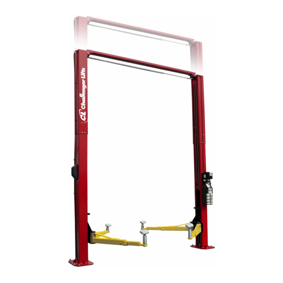
- Page 1 & M NSTALLATION PERATION AINTENANCE ANUAL Two Post Surface Mounted Lift LE12 ODEL 12,000 APACITY 3000 2311 South Park Rd., Louisville, Kentucky 40219 Email: Web site: sales@challengerlifts.com www.challengerlifts.com Office 800-648-5438 502-625-0700 Fax 502-587-1933 IMPORTANT: READ THIS MANUAL COMPLETELY BEFORE INSTALLING or OPERATING LIFT...
-
Page 2: General Specifications
Model LE12 Installation, Operation and Maintenance ENERAL PECIFICATIONS See Figure 1 LE12 LE12 w/ 2 Ft. Ext. Kit Rise Height (Screw Pads Highest Position) 77 3/4" (1975 mm) Overall Height 13’-10"/14’-7” 15’-10"/16’-7” (4216 mm/4445 mm) (4826mm/ 5055mm) Overall Width 139 3/4"... - Page 3 Model LE12 Installation, Operation and Maintenance Safety decals similar to those shown here ERTICAL LEARANCE are found on a properly installed lift. Be Check the height of the area where the lift is to sure that all safety decals have been be installed.
-
Page 4: For Installation
Model LE12 Installation, Operation and Maintenance ECEIVING NSTALLATION The shipment should be thoroughly inspected AFETY EQUIREMENTS NSTALLATION as soon as it is received. The signed bill of ERVICE lading is acknowledgement by the carrier of Refer to ANSI/ALI ALIS (current edition) - Page 5 Model LE12 Installation, Operation and Maintenance NCHORING 4) The anchor bolts must be installed at least 8” from any crack, edge, or expansion joint. 5) Use a concrete hammer drill with a 3/4 inch carbide bit. Tip diameter should conform to ANSI Standard B94.12-1977 (.775 to .787).
- Page 6 Model LE12 Installation, Operation and Maintenance Fig. 5 – Synchronizing Cables & H OWER YDRAULIC INES 19) Mount Power Unit to power column as shown in Fig. 6 using (4) M8 hex bolts and nuts. Fig. 6 – Hose Routing...
-
Page 7: Lock Release
Model LE12 Installation, Operation and Maintenance ELEASE 27) Install Lock Release Rod, Clevis, and Knob to the Power Column Lock using one M10 Nut. 28) Attach Mechanical Lock Release Cable Assembly to each lock pawl. See Fig. 8. Fig. 10 –... - Page 8 Model LE12 Installation, Operation and Maintenance 39) Connect Overhead Limit Switch Cord to (NOTE: pressure relief will make a high Contactor as shown. pitch squeal sound for these 10 seconds.) Check hydraulic system for leaks. 40) Connect Contactor to Power unit as shown.
- Page 9 Model LE12 Installation, Operation and Maintenance Fig 12 – Electrical Wiring Diagram Page 9 Rev. 12/15/20 LE12-IOM-A.
-
Page 10: Operation Procedure
Model LE12 Installation, Operation and Maintenance 90 ALI Safety Tips card; ANSI/ALI ALOIM-2008, PERATION ROCEDURE American National Standard for Automotive Lifts- Safety Requirements for Operation, Inspection AFETY OTICES AND ECALS and Maintenance; and in the case of frame This product is furnished with graphic safety... -
Page 11: Lifting A Vehicle
Model LE12 Installation, Operation and Maintenance IFTING A EHICLE OSS OF POWER 1) Ensure that the lifting arms are parked, out to If for any reason the lift will not rise off the locks full drive thru position. or the locks will not retract, consult factory authorized personnel. -
Page 12: Maintenance
Model LE12 Installation, Operation and Maintenance AINTENANCE Monthly To avoid personal injury, permit only qualified Torque concrete anchor bolts to 80 ft-lbs. personnel to perform maintenance on this equipment. Maintenance personnel should follow Check overhead shutoff switch. While raising lockout/tagout instructions per ANSI Z244.1. -
Page 13: Parts Breakdown
M12 HEX NUT IMPORTANT Replace all worn, damaged, or broken parts with parts approved by Challenger Lifts, Inc. or with parts meeting Challenger Lifts Inc. specifications. Contact your local Challenger Lifts parts distributor for pricing and availability. Call Challenger Lifts at (502) 625-0700 for the distributor in your area. - Page 14 M12 NUT IMPORTANT Replace all worn, damaged, or broken parts with parts approved by Challenger Lifts, Inc. or with parts meeting Challenger Lifts Inc. specifications. Contact your local Challenger Lifts parts distributor for pricing and availability. Call Challenger Lifts at (502) 625-0700 for the distributor in your area.
- Page 15 POWER UNIT IMPORTANT Replace all worn, damaged, or broken parts with parts approved by Challenger Lifts, Inc. or with parts meeting Challenger Lifts Inc. specifications. Contact your local Challenger Lifts parts distributor for pricing and availability. Call Challenger Lifts at (502) 625-0700 for the distributor in your area.
- Page 16 M12 x 45mm BOLT IMPORTANT Replace all worn, damaged, or broken parts with parts approved by Challenger Lifts, Inc. or with parts meeting Challenger Lifts Inc. specifications. Contact your local Challenger Lifts parts distributor for pricing and availability. Call Challenger Lifts at (502) 625-0700 for the distributor in your area.
- Page 17 M8 x 8 Set Screw Cup Point IMPORTANT Replace all worn, damaged, or broken parts with parts approved by Challenger Lifts, Inc. or with parts meeting Challenger Lifts Inc. specifications. Contact your local Challenger Lifts parts distributor for pricing and availability. Call Challenger Lifts at (502) 625-0700 for the distributor in your area.
- Page 18 Model LE12 Installation, Operation and Maintenance NOTES Page 18 Rev. 12/15/20 LE12-IOM-A.
- Page 19 Model LE12 Installation, Operation and Maintenance REVISIONS 03/06/20- UPDATED PART NUMBERS IN PARTS BREAKDOWN FOR POWER COLUMN, IDLER COLUMN, COLUMN EXTENSIONS, & OVERHEAD. 12/15/20-CHANGED POWER UNIT FROM 31368-19 TO AB-9367-DLH. UPDATED PARTS BREAKDOWN AND WIRING SCHEMATIC. Page 19 Rev.
Need help?
Do you have a question about the LE12 and is the answer not in the manual?
Questions and answers