
Subscribe to Our Youtube Channel
Related Manuals for REMKO MXT Series


Summary of Contents for REMKO MXT Series
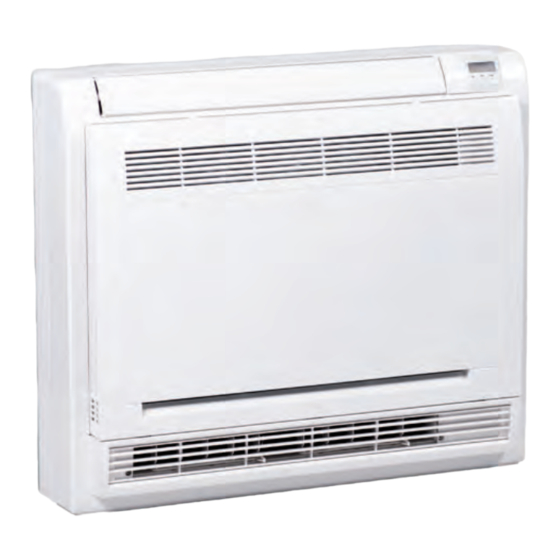
- Page 1 Operating and installation instructions REMKO MXT series Wall chest for cooling and heating MXT 264, MXT 354, 0223-2021-02 Edition 2, en_GB Read the instructions prior to performing any task!
- Page 2 Read these operating instructions carefully before commis- sioning / using this device! These instructions are an integral part of the system and must always be kept near or on the device. Subject to modifications; No liability accepted for errors or mis- Refrigerant prints! Translation of the original...
-
Page 3: Table Of Contents
Table of contents Safety and usage instructions......................4 1.1 General safety notes........................4 1.2 Identification of notes........................4 1.3 Personnel qualifications........................4 1.4 Dangers of failure to observe the safety notes................4 1.5 Safety-conscious working....................... 5 1.6 Safety instructions for the operator....................5 1.7 Safety notes for installation, maintenance and inspection ............. -
Page 4: Safety And Usage Instructions
REMKO MXT series Safety and usage instructions DANGER! This combination of symbol and signal word 1.1 General safety notes warns of a situation in which there is immediate danger, which if not avoided may be fatal or Carefully read the operating manual before com- cause serious injury. -
Page 5: Safety-Conscious Working
In particular, failure to observe the safety notes All housing parts and unit openings, e.g. air may pose the following risks: inlets and outlets, must be kept clear. The units must be inspected by a service tech- The failure of important unit functions. nician to ensure that they are safe to use and The failure of prescribed methods of mainte- fully functional at least once yearly. -
Page 6: Unauthorised Modification And Changes
"certificate of warranty" to The setup, connection and operation of the REMKO GmbH & Co. KG at the time when the units and its components must be undertaken units are purchased and commissioned. -
Page 7: Environmental Protection And Recycling
1.12 Environmental protection and recycling Disposal of packaging All products are packed for transport in environ- mentally friendly materials. Make a valuable contri- bution to reducing waste and sustaining raw mate- rials. Only dispose of packaging at approved collection points. Disposal of equipment and components Only recyclable materials are used in the manufac- ture of the devices and components. -
Page 8: Technical Data
REMKO MXT series Technical data 2.1 Unit data Series MXT 264 MXT 354 Wall chest for inverter multisplit Operating mode outdoor units for cooling and heating Nominal cooling output Nominal heat capacity Application area (room volume), approx. Adjustment range, room temperature °C... -
Page 9: Unit Dimensions
Series MXT 264 MXT 354 Dimensions Height Width Depth Weight 13.5 15.0 EDP no. 1623400 1623402 Air inlet temp. TK 27 °C / FK 19 °C, outside temperature TK 35 °C, FK 24 °C, max. air flow volume, 5 m pipe length Air inlet temp. -
Page 10: Design And Function
The indoor unit consists of a fin evaporator, evapo- rator fan, controller and condensate tray. The Fig. 3: Cooling cycle schematic indoor unit can be combined with REMKO outdoor units from the MVT 603 DC-1403 DC range that 1: Evaporator provide sufficient combination options. -
Page 11: Operation
Operation 4.1 General notes Alarms are indicated by a code (see chapter The indoor unit is easily operated using the Troubleshooting and customer service). standard infrared remote control. The indoor unit beeps to acknowledge the correct transmission of data. If it is not possible to program the indoor unit with the remote control, then it can also be man- ually operated. -
Page 12: Display On Indoor Unit
REMKO MXT series 4.2 Display on indoor unit Connection of the optional wired remote con- trol KFB-3 Display The wired remote control, type KFB-3, can be con- nected to the devices of the series MXT 264-354. You need the connection cable that is part of the delivery scope of the wired remote control for this. -
Page 13: Manual Air Distribution
4.3 Manual air distribution Setting the air distribution The vertical air control blades can be manually moved to the left and right (s. Fig. 7). An automatic swing function is also available for horizontal air distribution (s. Chapter “Buttons on the remote control”). - Page 14 REMKO MXT series Automatic selection of the blow-out side Operating mode Cooling mode Heating mode The unit blows out from the top and When the unit is When the unit is When the setpoint bottom side when started or when the...
-
Page 15: Keys On The Remote Control
17 °C. “Follow me” function ( ) - Network configuration ( “Fresh” key - “Follow me” function ( ) Activates/deactivates the REMKO BioClean func- The selected function flashes in the display, con- tion (ionisation). firm with the “OK” key. - Page 16 REMKO MXT series “Clean” key Time-delayed switch-on active. Activates/deactivates the self-cleaning function of the unit (available depending on the unit model). Time-delayed switch-off active. “LED” key Silent mode active. Enables switching on/off the unit lighting and the signal tones (depending on the unit).
- Page 17 Temperature setting Cooling mode The temperature setting can be made within a Press the “Mode” key and activate the “Cool” range of 17-30 °C. The setpoint is adjusted in 1 °C function. steps. Set the desired temperature using the “Λ ” and “V”...
- Page 18 REMKO MXT series Timer function Time-delayed switch-off With the “Timer” function, the unit can switch on Press the “Timer” key to enter the “Time with a switch-on delay or switch off with a switch- OFF” setting off delay. Use the arrow keys to select the desired...
- Page 19 Combining time-delayed switching on and off 14.00 15.00 15.30 16.00 17.00 18.00 13.00 Fig. 15: Combining time-delayed switching on and off 1: Timer starts a: current (13:00) 2: Unit switches on b: 2.5 hours later 3: Unit switches off c: 5 hours later Example: If both timers are activated at 13:00, the unit switches on 2.5 hours later (at 15:30) and switches off 5 hours later (at 18:00).
- Page 20 REMKO MXT series Deactivate lighting and signal tones Frost protection function Press the “LED” key to switch the unit lighting The air conditioning unit operates at high fan on and off. speed with a fixed setpoint of 8 °C (only available in heating mode).
- Page 21 Self-cleaning function “Turbo” function Press the “Clean” key (not available on all unit models). If the “Turbo” key is pressed in cooling mode, the unit operates with the highest possible cooling Due to the formation of condensate on the heat capacity and at the same time with the highest fan exchanger and the residual moisture that remains, speed.
- Page 22 AP mode (network configuration) Not available for all unit types and can only be used in combination with the optional REMKO WifiStick. AP mode can be activated by pressing the “LED” key several times within 10 seconds. The unit is now in net- work configuration mode.
-
Page 23: Installation Instructions For Qualified Personnel
Installation instructions Minimum clearances for qualified personnel Observe the minimum clearances to allow access for maintenance and repair work and facilitate Important notes prior to installation optimum air distribution. Observe the operating manuals for the indoor unit and the outdoor unit when installing the entire system. -
Page 24: Installation
REMKO MXT series Installation Connection of refrigerant piping The refrigerant pipes should be connected by the customer on the right-hand inner side of the unit. It NOTICE! may be necessary to fit a reducer or flared adapter to the outdoor unit. These fittings are included with Installation should only be performed by author- the outdoor unit as an accessory kit. -
Page 25: Condensate Drainage Connection And Safe Drainage
Condensate drainage Safe drainage in the event of leakages connection and safe Local regulations or environmental laws, for example the German Water Resource Act (WHG), drainage can require suitable precautions to protect against uncontrolled drainage in case of leakage to provide Condensate drainage connection for safe disposal of escaping air conditioning fluid If the temperature falls below the dew point on the... -
Page 26: Electrical Wiring
REMKO MXT series Electrical wiring 8.1 General notes Make the connection as follows: Open the air inlet grill. A protected power supply cable is to be connected to the outdoor unit and a four-core control line with Remove the covers on the right-hand side a minimum cross-section of 1.5mm... -
Page 27: Electrical Wiring Diagram
8.2 Electrical wiring diagram Connection MVT 603 DC-1403 DC L(A) N(A) S(A) L(B) N(B) S(B) 230V/1~/50 Hz L(C) N(C) S(C) L(D) N(D) S(D) Fig. 31: Electrical wiring diagram A: Outdoor unit MVT 603 DC-1403 DC 1: Power supply B: Indoor units MXT 264-354 2: Communication lines... - Page 28 REMKO MXT series Connection of optional condensate pump KP 6 / KP 8 L(1) 2(N) L(1) 2(N) N PE Fig. 32: Electrical wiring diagram Outdoor unit Condensate pump supply Indoor unit Condensate pump fault contact Condensate pump KP 6 / KP 8...
-
Page 29: Unit Type Selection And Temperature Compensation
8.3 Unit type selection and temperature compensation Unit type selection Temperature compensation Switch Switch Switch Type Switch Temperature setting setting MXT 264 6 °C SW 2 MXT 354 SW 102 4 °C 0 °C Factory setting Automatic restart after MO / MU power failure Switch Switch setting... -
Page 30: Electrical Drawings
REMKO MXT series 8.4 Electrical drawings MXT 264 CN15 CN10 Ge/Gn Ge/Gn CN1 CN2 Fig. 33: Electrical drawings MXT 264 Control board Evaporator fan motor Auxiliary circuit board Colour codes: Display circuit board blu: Blue Temperature probe, evaporator bro: Brown... - Page 31 MXT 354 CN10 CN15 TYPE Ge/Gn Ge/Gn CN1 CN2 Ge/Gn Fig. 34: Electrical drawings MXT 354 Control board Evaporator fan motor Auxiliary circuit board Colour codes: Display circuit board blu: Blue Temperature probe, evaporator bro: Brown Temperature probe, indoor air yel: Yellow Fin motor, top...
-
Page 32: Commissioning
REMKO MXT series Commissioning NOTICE! Check that the shut-off valves and valve caps NOTICE! are tight after carrying out any work on the Commissioning should only be performed by cooling cycle. Use appropriate sealant products specially trained personnel and documented as necessary. -
Page 33: Troubleshooting And Customer Service
Troubleshooting and customer service The unit and components are manufactured using state-of-the-art production methods and tested several times to verify their correct function. However, if alarms should occur, please check the functions as detailed in the list below. For systems with an indoor unit and outdoor unit, refer to the chapter "Troubleshooting and customer service"... - Page 34 REMKO MXT series Operational malfunctions (continued) Malfunction Possible causes Checks Remedial measures Filter is dirty / air inlet / Have the filters been Clean the filters outlet opening is blocked cleaned? by debris Windows and doors Have structural / usage Close windows and open.
- Page 35 Malfunction indicated by flashing code Operation light Error description LED timer (flashes each second) EEPROM error, indoor unit Communication error between indoor unit and outdoor unit Fan motor speed control not OK Room temperature probe defective Evaporator probe defective EC error - no cooling/heat output after 30 minutes Condensation pump float switch triggered (optional) Current consumption is too high Outdoor unit air inlet temperature probe faulty...
-
Page 36: Care And Maintenance
REMKO MXT series Care and maintenance Regular care and observation of some basic points will ensure trouble-free operation and a long This enables you to ensure the operational reli- service life. ability of the plant at all times! For systems which operate year-round (e.g. in... - Page 37 Cleaning the filter Disconnect the power supply to the unit. Open the front side of the unit by folding the grill down/forwards (Fig. 35). Pull the filter out in an upwards direction (Fig. 35). Clean the filter with a commercially available vacuum cleaner.
-
Page 38: Exploded View Of The Unit And Spare Parts List
REMKO MXT series Exploded view of the unit and spare parts list 12.1 Exploded view of the unit Fig. 38: Exploded view of the unit MXT 264-354 We reserve the right to modify the dimensions and design as part of the ongoing technical development... -
Page 39: Spare Parts List
12.2 Spare parts list IMPORTANT! To ensure the correct delivery of spare parts, please always the device type with the corresponding serial number (see type plate) No. Designation 1 Mounting plate Infrared remote control Connection terminals cover Fan impeller DC fan motor Fan motor bracket Fan motor mounting plate Front cover... -
Page 40: Shutdown
REMKO GmbH & Co. KG or your contractual residual humidity from the unit. partner will be pleased to provide a list of certified Shut down the system using the remote con- firms in your area. -
Page 41: Index
Index Remedial measures ....33 Manual air distribution ....13 Air distribution, manual . - Page 42 REMKO MXT series...
- Page 44 REMKO QUALITY WITH SYSTEMS Air-Conditioning | Heating | New Energies Telephone +49 (0) 5232 606-0 REMKO GmbH & Co. KG Hotline within Germany +49 (0) 5232 606-0 Klima- und Wärmetechnik Telefax +49 (0) 5232 606-260 Im Seelenkamp 12 E-mail info@remko.de...
Need help?
Do you have a question about the MXT Series and is the answer not in the manual?
Questions and answers