
Related Manuals for REMKO MXT Series


Summary of Contents for REMKO MXT Series
- Page 1 Operating and installation instructions REMKO MXT series Wall chest for cooling and heating MXT 355, MXT 525, 0323-2022-11 Edition 1, en_GB Read the instructions prior to performing any task!
- Page 2 Read these operating instructions carefully before commis- sioning / using this device! These instructions are an integral part of the system and must always be kept near or on the device. Subject to modifications; No liability accepted for errors or mis- Refrigerant prints! Translation of the original...
-
Page 3: Table Of Contents
Table of contents Safety and usage instructions......................4 1.1 General safety notes........................4 1.2 Identification of notes........................4 1.3 Personnel qualifications........................4 1.4 Dangers of failure to observe the safety notes................4 1.5 Safety-conscious working....................... 5 1.6 Safety instructions for the operator....................5 1.7 Safety notes for installation, maintenance and inspection ............. -
Page 4: Safety And Usage Instructions
REMKO MXT series Safety and usage instructions DANGER! This combination of symbol and signal word 1.1 General safety notes warns of a situation in which there is immediate danger, which if not avoided may be fatal or Carefully read the operating manual before com- cause serious injury. -
Page 5: Safety-Conscious Working
In particular, failure to observe the safety notes All housing parts and unit openings, e.g. air may pose the following risks: inlets and outlets, must be kept clear. The units must be inspected by a service tech- The failure of important unit functions. nician to ensure that they are safe to use and The failure of prescribed methods of mainte- fully functional at least once yearly. -
Page 6: Unauthorised Modification And Changes
"certificate of warranty" to The setup, connection and operation of the REMKO GmbH & Co. KG at the time when the units and its components must be undertaken units are purchased and commissioned. -
Page 7: Environmental Protection And Recycling
1.12 Environmental protection and recycling Disposal of packaging All products are packed for transport in environ- mentally friendly materials. Make a valuable contri- bution to reducing waste and sustaining raw mate- rials. Only dispose of packaging at approved collection points. Disposal of equipment and components Only recyclable materials are used in the manufac- ture of the devices and components. -
Page 8: Technical Data
REMKO MXT series Technical data 2.1 Unit data Series MXT 355 MXT 525 Wall chest for inverter multisplit Operating mode outdoor units for cooling and heating Nominal cooling output Nominal heat capacity Application area (room volume), approx. Adjustment range, room temperature °C... -
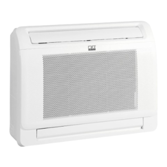
Page 9: Unit Dimensions
Series MXT 355 MXT 525 Dimensions Height Width Depth Weight 14.9 EDP no. 1623405 1623410 Distance 1 m free field 2.2 Unit dimensions Fig. 1: Unit dimensions MXT 355-525 (All measurements in mm) We reserve the right to modify the dimensions and design as part of the ongoing technical development process. -
Page 10: Design And Function
2: Evaporator fan orator fan, controller and condensate tray. The 3: Suction pipe connection indoor unit can be combined with REMKO outdoor 4: Injection pipe connection units from the MVT 603 DC-1403 DC range that provide sufficient combination options. The outdoor unit is controlled by the regulation of the indoor unit. -
Page 11: Operation
Operation 4.1 General notes The indoor unit is easily operated using the standard infrared remote control. The indoor unit beeps to acknowledge the correct transmission of data. If it is not possible to program the indoor unit with the remote control, then it can also be man- ually operated. -
Page 12: Indicators On Indoor Unit
Furthermore, the SmartControl Touch SC-1 (Smart-Com) central regulation can be connected. (See “Electrical wiring” chapter). Operation via the REMKO Smart web portal or REMKO Smart Control app The units in the MXT 355-525 series can be con- trolled with a connected SC-1 (Smart-Com) or a plugged-in WIFI stick via the REMKO Smart web portal or via the REMKO Smart-Control app. -
Page 13: Manual Air Distribution
4.3 Manual air distribution Setting the air distribution The vertical air control slats can be moved to the left and right by hand (see Fig. 9). An automatic swing function is also available for horizontal air distribution (see Chapter “Keys on the remote con- trol”). -
Page 14: Keys On The Remote Control
REMKO MXT series 4.4 Keys on the remote control "Fan speed" key Switches between the different fan speeds in the following order: AUTO Þ20% Þ40% Þ60% Þ80% Þ100% Þ... The fan speed can also be adjusted in 1% steps with the "Arrow up" and "Arrow down" keys. - Page 15 "eco gear" key Additional functions Switches between the available energy-saving Breathe Away functions in the following order: Self clean eco Þ gear 75 % Þ gear 50 % Þ OFF Þ eco ... Bio Clean eco: Sleep the setpoint is raised to 24 °C and the fan speed is Follow me set to automatic.
- Page 16 REMKO MXT series Key lock Key functions "Auto" mode Appears when the remote control key lock is active. Make sure that the indoor unit is connected to the power supply, and is switched on. The operating mode indicator on the display of the Temperature indicators indoor unit begins to flash.
- Page 17 "Cooling", "Heating" and "Recirculation" mode "Dehumidification" mode Press the "ON/OFF" key [1] to switch on the Press the "ON/OFF" key [1] to switch on the air conditioning unit. air conditioning unit. Press the "MODE" key [2] to select Press the "MODE" key [2] to select "Dehu- "Cooling", "Heating"...
- Page 18 REMKO MXT series "Timer" mode Press the "TIMER" key to set the "switch-on time" and the "switch-off time" for the unit. When the switch-on and switch-off times are being set, this can be done at 30 minute inter- Setting the "switch-on time"...
- Page 19 Examples of TIMER function settings Combined TIMER (setting "TIMER ON" and "TIMER OFF" at the same time) "TIMER ON" (Auto on mode) "TIMER OFF ð "TIMER ON" Example: (On ð Stop ð Start) You want the air conditioning unit to switch on 2 hours from the time it was programmed.
- Page 20 REMKO MXT series Sleep Frost protection function The frost protection function keeps the room air The sleep function can be used to save energy temperature above 8 °C to prevent damage to the during night operation. When the sleep function is activated, the temperature setpoint is regularly building structure.
- Page 21 Key lock The frost protection function keeps the room air temperature above 8°C to prevent damage to the building structure. Press the “Turbo” key [1] and the “Humidity” key [2] at the same time for 5 seconds to activate and deactivate the key lock.
-
Page 22: Installation Instructions For Qualified Personnel
REMKO MXT series Installation instructions Installation material for qualified personnel The indoor unit is attached to the wall by a wall bracket and 4 screws (to be provided by the cus- Important notes prior to installation tomer). Observe the operating manuals for the indoor unit... - Page 23 Connection variants The following connection variants can be used for the refrigerant, condensate and control lines. Fig. 25: Connection variants A: Outflow, right C: Bottom outflow B: Outflow, left D: Rear outflow...
- Page 24 REMKO MXT series Dimensions of rear of unit Fig. 26: Rear of unit base dimensions (all measurements in mm) A: Wall-mounted bracket C: Wall opening B: Spacer...
-
Page 25: Installation
Installation Connection of refrigerant piping The refrigerant pipes should be connected by the customer on the right-hand inner side of the unit. It NOTICE! may be necessary to fit a reducer or flared adapter to the outdoor unit. These fittings are included with Installation should only be performed by author- the outdoor unit as an accessory kit. -
Page 26: Condensate Drainage Connection And Safe Drainage
REMKO MXT series Condensate drainage Safe drainage in the event of leakages connection and safe Local regulations or environmental laws, for example the German Water Resource Act (WHG), drainage can require suitable precautions to protect against uncontrolled drainage in case of leakage to provide... -
Page 27: Electrical Wiring
Electrical wiring 8.1 General notes Connection of the power supply and control line A protected power supply cable is to be connected Make the connection as follows: to the outdoor unit and four-core control line with minimum cross-section 1.5mm is to be connected Open the air inlet grille (see Fig. - Page 28 REMKO MXT series Connection of an optional wired remote control (KFB-3) A wired remote control (KFB-3) can optionally be connected to the units of the MXT 355-525 series. Make the connection as follows: Open the air inlet grille (see Fig. 29).
- Page 29 PCB: CN46 CN42 CN41 CN45 REMKO Smart-Control Touch SC-1 REMKO Smart-Control Touch SC-1 Smart- REMKO Redundancy Module KFB-R Customer-provided superordinate regulation Fig. 34: Connections of the multifunction PCB External “on/off” contact The external “on/off” contact enables external ena- bling or disabling of the indoor unit from a remote location.
- Page 30 REMKO MXT series Rotary switch addressing Connection of an optional central regulation (SC-1, SC-1 Smart-Com) The address of the indoor unit is determined using A central regulation (SC-1) can optionally be con- the rotary switch in combination with the DIP switches (see chapter “Addressing”).
- Page 31 Addressing the indoor unit (SC-1, SC-1 Smart- The rotary switch ENC3 is then used to specify the Com) unit address more precisely. The unit address results from the combination of the two switches as Indoor units that are connected to a central regula- follows: tion system must be assigned a unit address from 0 to 63 for assignment in the unit bus.
- Page 32 REMKO MXT series Connection of an optional redundancy module Installation of an optional WIFI stick (KFB-R) The units of the MXT 355-525 series are equipped A redundancy module (KFB-R) can be optionally with an interface for a WIFI stick as standard, connected to the units of the MXT 355-525 series.
-
Page 33: Electrical Wiring Diagram
8.2 Electrical wiring diagram Connection MVT 603 DC-1403 DC L(A) N(A) S(A) L(B) N(B) S(B) 230V/1~/50 Hz L(C) N(C) S(C) L(D) N(D) S(D) Fig. 41: Electrical wiring diagram A: Outdoor unit MVT 603 DC-1403 DC 1: Power supply cable B: Indoor units MXT 355-525 2: Communication lines... - Page 34 REMKO MXT series Connection of optional condensate pump KP 6/KP 8 1(L) 2(N) L(A) N(A) S(A) PE 230 V/1~/50 Hz Fig. 42: Electrical wiring diagram Outdoor unit Condensate pump supply Indoor unit Condensate pump fault contact Condensate pump KP 6/KP 8...
-
Page 35: Electrical Drawings
8.3 Electrical drawings MXT 355-525 CN81 CN32 CN12 CN42 CN23 CN19 CN15 ge (ws) CN18 ge/gn L N S 13 14 15 16 Fig. 43: Electrical drawings MXT 355-525 Control board Temperature probe, indoor air Display circuit board Room air humidity sensor Multifunction PCB Wired remote control connection Evaporator fan, bottom... -
Page 36: Commissioning
REMKO MXT series Commissioning NOTICE! Check that the shut-off valves and valve caps NOTICE! are tight after carrying out any work on the Commissioning should only be performed by cooling cycle. Use appropriate sealant products specially trained personnel and documented as necessary. -
Page 37: Troubleshooting And Customer Service
Troubleshooting and customer service The unit and components are manufactured using state-of-the-art production methods and tested several times to verify that they function correctly. However, if malfunctions do occur, please check the functions as detailed in the list below. For systems with an indoor unit and outdoor unit, refer to the chapter "Trouble- shooting and customer service"... - Page 38 REMKO MXT series Operational malfunctions (continued) Malfunction Possible causes Checks Remedial measures Filter is dirty/air inlet/ Have the filters been Clean the filters outlet opening is blocked cleaned? by debris Windows and doors Have structural/usage Close windows and open. Heating/cooling...
- Page 39 Status/fault display on the indoor unit Indicator Error description Defrosting active (status) Self clean function active (status) No enabling (external On / Off) (status) EH 00 EEPROM error, indoor unit EH 0A EL 01 Communication error between indoor unit and outdoor unit EH 03 Fan speed control indoor unit disabled EH 31...
-
Page 40: Care And Maintenance
REMKO MXT series Care and maintenance Regular care and observation of some basic points will ensure trouble-free operation and a long This enables you to ensure the operational reli- service life. ability of the plant at all times! For systems which operate year-round (e.g. in... - Page 41 Cleaning the filter Disconnect the power supply to the unit. Open the front side of the unit by folding the grill down/forwards (Fig. 44). Pull the filter out in an upwards direction (Fig. 44). Clean the filter with a commercially available vacuum cleaner.
-
Page 42: View Of Unit And Spare Parts List
REMKO MXT series View of unit and spare parts list 12.1 View of the unit Fig. 47: View of the unit MXT 355-525 We reserve the right to modify the dimensions and design as part of the ongoing technical development... -
Page 43: Spare Parts List
12.2 Spare parts list IMPORTANT! To ensure the correct delivery of spare parts, please always the device type with the corresponding serial number (see type plate) No. Designation No. Designation Front panel Fan motor, bottom Air filter Air outlet slats, bottom, set Housing front Slat motor, bottom Condensate tray... -
Page 44: Shutdown
REMKO GmbH & Co. KG or your contractual residual humidity from the unit. partner will be pleased to provide a list of certified Shut down the system using the remote con- firms in your area. -
Page 45: Index
Index Manual mode ......11 Minimum clearances ..... 22 Air distribution, manual . - Page 46 REMKO MXT series...
- Page 48 REMKO QUALITY WITH SYSTEMS Air-Conditioning | Heating | New Energies Telephone +49 (0) 5232 606-0 REMKO GmbH & Co. KG Hotline within Germany +49 (0) 5232 606-0 Klima- und Wärmetechnik Telefax +49 (0) 5232 606-260 Im Seelenkamp 12 E-mail info@remko.de...
Need help?
Do you have a question about the MXT Series and is the answer not in the manual?
Questions and answers