Table of Contents
Advertisement
Quick Links
Stop position adjustment range
Stop position adjustment range
±10
±10
From center:
From center:
Rotation range:
Rotation range:
The desired position is adjustable to
between 0 and 95° from the centered
position to both the right and left
sides.
Can be operated by a single valve.
Can be operated by a single valve.
Controllable with one 3-position solenoid valve.
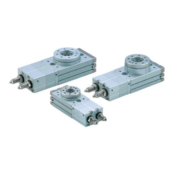
3 - Position Rotary Table
˚
˚
0~95
0~95
˚
˚
MSZ
Series
CAT.ES20-187
Sorts work to the right or left side
A
Advertisement
Table of Contents

Related Manuals for SMC Networks MSZ Series


Summary of Contents for SMC Networks MSZ Series
- Page 1 CAT.ES20-187 3 - Position Rotary Table Stop position adjustment range Stop position adjustment range ±10 ±10 ˚ ˚ From center: From center: 0~95 0~95 ˚ ˚ Rotation range: Rotation range: The desired position is adjustable to between 0 and 95° from the centered position to both the right and left sides.
- Page 2 Example of Stop Position Settings Angle adjustable as shown below. (CCW: Counterclockwise, C: Center, CW: Clockwise) Left 90°: Right 90° Left 45°: Right 45° Left 90°: Right 30° Left 60°: Right 90° Working Principle This model uses a 3-position 5-port solenoid valve End of counterclockwise direction Piston for center stop Piston for rotary operation...
-
Page 3: Model Selection
Series Model Selection Model Selection Procedure Formula Selection Example Operating conditions Enumerate the operating conditions according to the mounting position. . Model used . Operating pressure . Mounting orientation . Load type Static load: Ts (N⋅m) ·H Resistance load: Tf (N⋅m) Inertia load: Ta (N⋅m) Vertical Mounting . -
Page 4: Allowable Load
Series Effective Torque Load Type Unit: N·m bStatic load: Ts Operating pressure (MPa) Operating A load as represented by the clamp which requires Size direction pressing force only End Center 0.38 0.60 0.83 1.06 1.28 1.51 1.73 1.96 2.18 During examination if it is decided to consider the mass of the clamp itself in the drawing below, it should be regarded Center End 0.29... - Page 5 Series Model selection Inertial Moment Formula (Calculation of Inertial Moment Ι) Ι: Inertial moment kg⋅m m: Load mass kg (1) Thin shaft (2) Thin shaft (3) Thin rectangular plate (4) Thin rectangular plate (Rectangular parallelepiped) (Rectangular parallelepiped) Position of rotational axis: Position of rotational axis: Perpendicular to the shaft Through the shaft's center of...
- Page 6 Series Kinetic Energy/Rotation Time (3) Model selection Select models by applying the inertial moment and rotation time which have been found to the charts below. MSZ 50A 0.01 MSZ 30A MSZ 20A 0.001 MSZ 10A 0.0001 0.00001 Rotation time (s/90°) Rotation Accuracy: Displacement Values at 180°...
- Page 7 Series Model selection Table Displacement (Reference values) • The following graphs show the displacement at point A, which is 100 mm apart from the center of rotation, where the load is applied. Load MSZ 10A MSZ 20A Load N Load N MSZ 30A MSZ 50A Load N...
-
Page 8: Rotary Table
Rotary Table Air Consumption Air consumption is the volume of air which is expended by the rotary actuator’s reciprocal operation inside the actuator and in the piping between the actuator and the switching valve, etc. This is necessary for selection of a compressor and for calculation of its running cost. To select a compressor, it is important to select one that has P+0.1 plenty of margin to accommodate the total air volume that is... -
Page 9: How To Order
3-Position Rotary Table Series 10, 20, 30, 50 Size : How to Order MSZA High precision type MSZB Basic type Number of auto switches 2 pcs. Size “n” pcs. Auto switch Without auto switch (Built-in magnet) With adjustment bolt Applicable Auto Switch Refer to pages 7 to 11 for detailed auto switch specification. -
Page 10: Specifications
Series Specifications Size Fluid Air (non-lube) Maximum operating pressure 1MPa Minimum operating pressure 0.2 MPa Ambient and fluid temperature 0 to 60°C (with no freezing) Cushion None Rotation angle adjustment range 0 to 190° ± 10° Center position adjustment range Port size M5 x 0.8 Allowable Kinetic Energy and Rotation Time Adjustment Range... -
Page 11: Angle Adjustment
Series 3-Position Rotary Table Angle Adjustment 1) Stop positions are adjusted with the adjusting Figure 4 Adjusting bolt position bolts shown in Figure 4. q Adjusting bolts “a” and “b” are used for Adjusting bolt c adjusting the rotation ends. Adjusting bolts Adjusting bolt a “c”... - Page 12 Series Construction !6 @9 !8 @6 !2 #1 t @1 i r w MSZA A (High precision type) Component Parts Description Material Description Material Body Aluminium alloy Basic type Deep groove ball bearing Bearing steel Cover Aluminium alloy High precision type Angular contact ball bearing SPCC Plate...
- Page 13 Series 3-Position Rotary Table Dimensions Basic type/MSZB A WD depth WE (circumference: 8 equivalents) depth 8 through counterbore depth ø ø ø 4 x M5 x 0.8 (Piping parts) ø (Through) ø (Max ≅ depth View High precision type/MSZA A ø...
-
Page 14: Proper Auto Switch Mounting Position
Series Proper Auto Switch Mounting Position Magnet Operating range proper mounting position (Lm/2) Most sensitive position Operating range of single auto switch (Lm) Reed switch Solid state switch D-A9 , D-A9 V D-F9 W, D-F9 WV, D-F9BAL D-M9 , D-M9 V Size Rotation Operating... - Page 15 Series Auto Switch Specifications Auto Switch Common Specifications Type Reed switch Solid state switch Leakage current None 3-wire: 100 µA or less, 2-wire: 0.8 mA or less Operating time 1.2 ms 1 ms or less Impact resistance 300 m/s 1000 m/s Insulation resistance 50 MΩ...
- Page 16 Auto Switch Connections and Examples Basic Wiring 2-wire Solid state 3-wire, NPN Solid state 3-wire, PNP 2-wire (Solid state) (Reed) Brown Brown Load Load Brown Indicator Brown Load Switch light, Switch Switch Black main Black protection main main circuit circuit, circuit circuit Load...
- Page 17 Reed Switch: Direct Mounting Style D-A90(V)/D-A93(V)/D-A96(V) For details about certified products conforming to Auto Switch Specifications international standards, visit us at www.smcworld.com. Grommet PLC: Programmable Logic Controller D-A90/D-A90V (Without indicator light) Electrical entry: In-line D-A90/D-A90V Auto switch part no. Applicable load IC circuit, Relay, PLC Load voltage 24 V AC/DC or less...
- Page 18 Solid State Switch: Direct Mounting Style D-M9N(V)/D-M9P(V)/D-M9B(V) For details about certified products conforming to Auto Switch Specifications international standards, visit us at www.smcworld.com. Grommet PLC: Programmable Logic Controller D-M9„, D-M9„V (With indicator light) 2-wire load current is reduced (2.5 to 40 mA) Auto switch part no.
- Page 19 2-color Indication Type, Solid State Switch: Direct Mounting Style D-F9NW(V)/D-F9PW(V)/D-F9BW(V) For details about certified products conforming to Auto Switch Specifications international standards, visit us at www.smcworld.com. Grommet PLC: Programmable Logic Controller D-F9 „ W/D-F9 „ WV (With indicator light) Auto switch part no. D-F9NW D-F9NWV D-F9PW...
-
Page 20: Safety Instructions
Series Safety Instructions These safety instructions are intended to prevent a hazardous situation and/or equipment damage. These instructions indicate the level of potential hazard by labels of “Caution”, “Warning” or “Danger”. To ensure safety, be sure to observe ISO 4414 Note1) , JIS B 8370 Note2) - Page 21 Series Auto Switch Precautions 1 Be sure to read before handling. Design and Selection Warning Caution 1. Confirm the specifications. 1. Take precautions when multiple cylinders are used close together. Read the specifications carefully and use this product appro- priately. The product may be damaged or malfunction if it is When two or more auto switch actuator are lined up in close used outside the range of specifications of current load, vol- proximity to each other, magnetic field interference may cause...
- Page 22 Series Auto Switch Precautions 2 Be sure to read before handling. Mounting and Adjustment Wiring Warning Warning 1. Instruction manual. 1. Confirm proper insulation of wiring. Install the products and operate them only after reading the in- Be certain that there is no faulty wiring insulation (such as struction manual carefully and understanding its contents.
- Page 23 Series Auto Switch Precautions 3 Be sure to read before handling. Wiring Operating Environment Caution Warning 4. Avoid incorrect wiring. 1. Never use in an atmosphere of explosive gases. <Reed switch> The construction of the auto switch is not intended to prevent explosion.
- Page 24 Series Auto Switch Precautions 4 Be sure to read before handling. Operating Environment Caution 1. Avoid accumulation of iron debris or close contact with magnetic substances. When a large accumulated amount of ferrous waste such as machining chips or welding spatter, or a magnetic substance (something attracted by a magnet) is brought into close prox- imity to an actuator with auto switches, this may cause the auto switches to malfunction due to a loss of the magnetic...
- Page 25 MSZ / Specfic product precautions Series Be sure to read before handling. Please refer to “Precautions for Handling Pneumatic Devices” (M-03-E3A) for Safety Instructions and Actuators/Auto Switch Precautions. Operation which requires no stop at the center position Behavior in the power-off condition Caution Caution 1.
- Page 28 SMC'S GLOBAL MANUFACTURING, DISTRIBUTION AND SERVICE NETWORK EUROPE NORWAY SINGAPORE SMC Pneumatics Norway A/S SMC Pneumatics (S.E.A.) Pte. Ltd. AUSTRIA POLAND SMC Pneumatik GmbH SOUTH KOREA SMC Industrial Automation Polska Sp.z.o.o. SMC Pneumatics Korea Co., Ltd. BELGIUM ROMANIA SMC Pneumatics N.V./S.A. TAIWAN SMC Romania s.r.l.
Need help?
Do you have a question about the MSZ Series and is the answer not in the manual?
Questions and answers