
Related Manuals for SMC Networks MHM-16D Series


Summary of Contents for SMC Networks MHM-16D Series
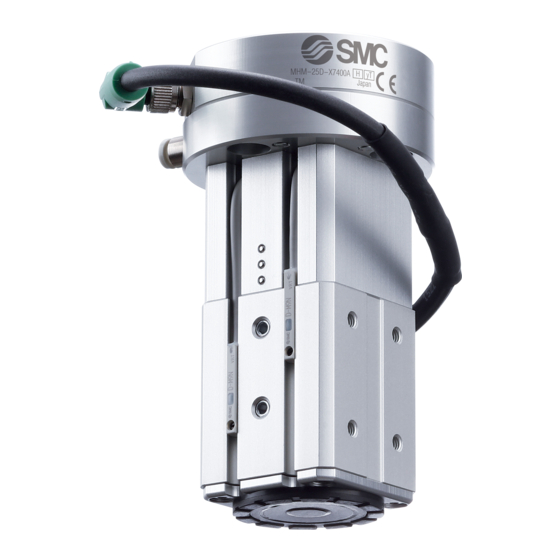
- Page 1 Doc. no.MH*-OMX0012 PRODUCT NAME Magnet Gripper MODEL / Series / Product Number MHM-16D* MHM-25D* MHM-32D* MHM-50D*...
-
Page 2: Table Of Contents
Contents Product outline Attracts and holds heavy objects with a magnet Transfers steel plates without a vacuum Holding force (Attraction force) can be adjusted. Safety Instructions 1. Specifications 2. Installation 2-1 Design 2-2 Mounting 2-3 Environment 2-4 Air supply 2-5 Piping 2-6 Lubrication 2-7 Auto Switch Mounting 2-8 Other... - Page 3 Safety Instructions These safety instructions are intended to prevent hazardous situations and/or equipment damage. These instructions indicate the level of potential hazard with the labels of “Caution,” “Warning” or “Danger.” They are all important notes for safety and must be followed in addition to International Standards (ISO/IEC)*1) , and other safety regulations.
- Page 4 Safety Instructions Caution The product is provided for use in manufacturing industries. The product herein described is basically provided for peaceful use in manufacturing industries. If considering using the product in other industries, consult SMC beforehand and exchange specifications or a contract if necessary. If anything is unclear, contact your nearest sales branch.
-
Page 5: Specifications
1. Specifications Model MHM-16D□ MHM-25D□ MHM-32D□ MHM-50D□ Pilot port M5x0.8 Rc1/8 Fluid Action Double acting Workpiece 0.2 to 0.6MPa thickness ≦ 2 mm Operating pressure Workpiece 0.2 to 0.6MPa 0.35 to 0.6MPa thickness > 2 mm Proof pressure 0.9MPa Ambient and fluid temperatures −10 to 60 C (No freezing) Workpiece... -
Page 6: Mounting
Caution 1. If pressure is applied to the external magnet gripper parts, there is a possibility that air will get inside the cylinder from the rod seal section. ( Example : inside a chamber, etc.) 2. Keep away from objects which are influenced by magnets. As the body magnets are built-in, do not allow close contact with magnetic disks, magnetic cards, or magnetic tapes. - Page 7 1) Lateral mounting Tightening Max. screw-in Model torque Applicable bolt depth L(mm) (N・m) MHM-16D□ M3x0.5 0.63 MHM-25D□ M4x0.7 MHM-32D□ M5x0.8 MHM-50D□ M6x1 2) Axial mounting (Central mounting type) Tightening Max. screw-in torque Model Applicable bolt depth L(mm) (N・m) MHM-16D□ M6x1 11.5 MHM-25D□...
-
Page 8: Environment
2-3 Environment Warning 1. Do not use in an atmosphere containing corrosive gases, chemicals, sea water, water, water steam, or where there is direct contact with any of these. Refer to each construction drawing for information on the materials of air grippers. 2. -
Page 9: Piping
2-5 Piping 1. Preparation before piping Before piping is connected, it should be thoroughly blown out with air (flushing) or washed to remove chips, cutting oil, and other debris from inside the pipe. 2. Winding of sealant tape When screwing piping or fittings into ports, ensure that chips from the pipe threads or sealing material do not enter the piping. -
Page 10: Auto Switch Mounting
2-7 Auto Switch Mounting Auto Switch Mounting Position Setting 1) Detect the magnet position for 2) Detect the magnet position for Detection example workpiece holding. workpiece release. Position to be detected Head side Magnet attraction side Magnet head side Attraction side Step 1) Hold the workpiece. - Page 11 *)The auto switch reacts at 2 places when the magnet is at the head side (workpiece release). At C3 in the waveform chart, the magnet position cannot be detected. C1: Detection area of the magnet position for workpiece release C2: Detection area of the magnet position for workpiece holding C3: Area where the magnet position cannot be Detected Auto Switch Mounting Position and Mounting Method Table below shows the mounting positions and dimensions of the auto switch.
-
Page 12: D-M9□V D-M9
*1 When detecting the magnet position for workpiece holding with adjustable holding force type, the mounting position of the auto switch needs to be changed depending on the adjustment amount of the holding force. * Dimensions above are for reference. Keep 1 mm or more clearance between the auto switch and peripheral equipment to avoid any interference. - Page 13 2. Keep a gap wider than the values listed in the table when arranging the magnet grippers side by side or when placing the magnet grippers close to magnetic objects such as iron. Required Gap (mm) Model MHM-16D□ MHM-25D□ MHM-32D□ MHM-50D□...
-
Page 14: Other
Examples of AND (Series) and OR (Parallel) Connections When using solid state auto switches, ensure the application is set up so the signals for the first 50 ms are invalid.Depending on the operating environment, the product may not operate properly. 2-8 Other 1) Refer to the Fittings and Tubing Precautions (Web Catalog) for handling One-touch fittings. -
Page 15: Adjustment
Caution 3) When multiple magnet grippers are used side by side, mount them so that the attraction surfaces are not uneven. Otherwise, adequate holding force is not available and the workpiece may slip or fall. 3.Adjustment Holding Force Adjustment 1. Turn the nut B to loosen while 3. -
Page 16: How To Order
Caution 1. Do not apply external forces to the holding force adjusting part other than for the purpose of holding force adjustment. Do not fix the holding force adjusting part to the outside or attempt to rotate it. 2. Take safety measures during the adjustment of the holding force. The workpiece may drop. 3. -
Page 17: Maintenance
5. Maintenance 5-1 Maintenance or inspection Warning 1. Perform maintenance and inspection according to the procedures indicated in the operation manual. If handled improperly, human injury and/or malfunction or damage of machinery and equipment may occur. 2. Maintenance work If handled improperly, compressed air can be dangerous. Assembly, handling, repair, and element replacement of pneumatic systems should be performed by a knowledgeable and experienced person. -
Page 18: Maintenance
2) Replace the pad using the following procedure. Model MHM-16D□ MHM-A1613 MHM-25D□ MHM-A2513 MHM-32D□ MHM-A3213 MHM-50D□ MHM-A5013 Fit the new pad into Remove the old pad Make sure that the pad the groove is correctly in place (The pad is not lifted from the surface) 5-3 Maintenance Warning... - Page 19 Revision history 4-14-1, Sotokanda, Chiyoda-ku, Tokyo 101-0021 JAPAN Tel: + 81 3 5207 8249 Fax: +81 3 5298 5362 https://www.smcworld.com Note: Specifications are subject to change without prior notice and any obligation on the part of the manufacturer. © 2019 SMC Corporation All Rights Reserved - 19 -...
Need help?
Do you have a question about the MHM-16D Series and is the answer not in the manual?
Questions and answers