
Related Manuals for SMC Networks MHF2-8D Series


Summary of Contents for SMC Networks MHF2-8D Series
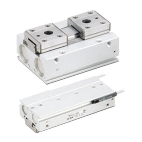
- Page 1 Product Name Compact Air Gripper Model / Series / Product Number MHF2-8D* MHF2-12D* MHF2-16D* MHF2-20D* MHF2-25D* MHF2-32*D*...
-
Page 2: Table Of Contents
Contents Safety Instructions 1. Product Specifications 1-1. Specifications 2. Operating Method / Operation 2-1. Precautions for Design 2-2. Selection 2-3. Installation 2-4. Air supply 2-5. Piping 2-6. Operating Environment 2-7. Lubrication 3. Maintenance 3-1. Precautions 3-2. Disassembly Drawing 1 Disassembly Drawing 2 Disassembly Drawing 3 3-3. -
Page 3: Safety Instructions
Safety Instruction These safety instructions are intended to prevent hazardous situations and/or equipment damage. These instructions indicate the level of potential hazard with the labels of “Caution,” “Warning” or “Danger.” They are all important notes for safety and must be followed in addition to International Standards (ISO/IEC)*1),and other safety regulations. ※1) ISO 4414: Pneumatic fluid power - General rules and safety requirements for systems and their components ISO 4413: Hydraulic fluid power -- General rules and safety requirements for system and their components IEC 60204-1: Safety of machinery -- Electrical equipment of machines (Part 1: General requirements) -
Page 4: Limited Warranty And Disclaimer/Compliance Requirements
Safety Instruction Caution We develop, design, and manufacture our products to be used for automatic control equipment, and provide them for peaceful use in manufacturing industries. Use in non-manufacturing industries is not covered. Products we manufacture and sell cannot be used for the purpose of transactions or certification specified in the Measurement Act. The new Measurement Act prohibits use of any unit other than SI units in Japan. -
Page 5: Product Specifications
1. Product Specifications 1-1. Specifications Specifications Model MHF2-8D* MHF2-12D* MHF2-16D* MHF2-20D* MHF2-25D* MHF2-32*D* Bore size (mm) Fluid Operating pressure (MPa) 0.15 to 0.7 0.1 to 0.7 Ambient and fluid temperature (℃) -10 to 60 (No freezing) Note 1) Repeatability (mm) ±0.05 ±0.04 Short stroke... -
Page 6: Operating Method / Operation
2. Operating Method / Operation 2-1. Precautions for Design Warning 1. The product is designed for use only in compressed air systems. Do not operate at pressures or temperatures, etc., beyond the range of the specifications, as this can cause damage or malfunction of the cylinder and other equipment. - Page 7 2. Attachments should be designed to be as light and short as possible. (1) A long or heavy attachment increases the inertia force required to open or close the fingers. This may cause unsteady movement of fingers and have an adverse affect on the life of the gripper.
-
Page 8: Installation
2-3. Installation Warning 1. Install and operate the product only after reading the Operation Manual carefully and understanding its contents. Keep the manual where it can be referred to as necessary. 2. Allow sufficient space for maintenance and inspection. 3. Do not scratch or dent the air gripper by dropping or bumping it when mounting. Slight deformation can cause inaccuracies or a malfunction. - Page 9 How to Mount Air Gripper Top mounting (Body tapped) Lateral mounting (Body tapped) Lower side mounting (Body tapped)
- Page 10 Body through-hole...
- Page 11 Caution 1. To mount the attachment to the finger, make sure not to apply undue strain on the finger. Any damage to the gripper may cause malfunction and reduce the accuracy. 2. Avoid external force to the finger. Fingers may be damaged by a continual lateral or impact load. Provide clearance to prevent the workpiece or the attachment from striking against any object at the stroke end.
-
Page 12: Air Supply
3. Adjust the gripping point so that an excessive force will not be applied to the fingers when inserting a workpiece. Confirm that the gripper can operate without receiving any shock by testing it in manual operation mode or by low speed operation. 4. -
Page 13: Piping
4. Use the product within the specified fluid and ambient temperature range. When operating at temperatures below 5℃, moisture in the circuit may freeze and cause breakage of seals or a malfunction. Corrective measures should be taken to prevent freezing. For detailed information regarding the quality of the compressed air described above, refer to SMC's "Air Cleaning Systems". -
Page 14: Maintenance
3. Maintenance 3-1. Precautions Warning 1. Maintenance should be performed according to the procedure indicated in the Operation Manual. Improper handling can cause an injury, damage and/or malfunction of equipment and machinery. 2. If handled improperly, compressed air can be dangerous. Assembly, handling, repair and element replacement of pneumatic systems should be performed by a knowledgeable and experienced person. -
Page 15: Disassembly Drawing
3-2. Disassembly Drawing 1... - Page 16 Disassembly Drawing 2...
- Page 17 Disassembly Drawing 3...
-
Page 18: Replacement Procedure
3-3. Replacement Procedure 1 (Applicable models:MHF2-8D,MHF2-8D1) 1. Loosen the guide bolts and remove the finger assembly. 2. Remove the clips, cap B assemblies, and cap C assemblies. 3. Remove the pinion. (Make sure to align the groove of the rack and the pinion shaft when they are assembled.) 4. - Page 19 Replacement Procedure 2 (Applicable models:MHF2-8D2,MHF2-12D* to 20D*) 1. Loosen the guide bolts and remove the finger assembly. Hexagon w rench size Nominal φ8 φ12 φ16 φ20 Number of guide bolts Short stroke Middle stroke Long stroke φ8 φ12 φ16 φ20 2.
- Page 20 Replacement Procedure 3 (Applicable models:MHF2-25D*,32*D*) 1. Loosen the guide bolts and remove the finger assembly. Guide bolt Hexagon wrench Finger assembly Body assembly Precautions for condition in which finger assembly is dismounted Finger Finger end surface A Finger end surface B Guide rail Guide rail end surface B Guide rail end surface A...
- Page 21 3-4. Construction/Parts list 1 MHF2-8D,MHF2-8D1 Components Description Material Note Description Material Note Body Aluminum alloy Hard anodizing Wear ring Synthetic resin Piston Stainless steel High carbon chromium Cross roller bearing steel Joint Stainless steel Heat treatment Guide rail Stainless steel Heat treatment High carbon chromium Needle roller...
- Page 22 Construction/Parts list 2 MHF2-12D* to 20D* Components Description Material Note Description Material Note Body Aluminum alloy Hard anodizing High carbon chromium Needle roller bearing steel Piston Aluminum alloy White anodized Aluminum Joint Stainless steel Heat treatment φ12:R-shaped retaining ring Guide rail Stainless steel Heat treatment Carbon steel...
- Page 23 Construction/Parts list 3 MHF2-25D*,32*D* Components Description Material Note Description Material Note Body Aluminum alloy Hard anodizing High carbon chromium Steel ball bearing steel Joint Stainless steel Heat treatment Guide rail Stainless steel Heat treatment 14 Wear ring Synthetic resin 15 Parallel pins Stainless steel High carbon chromium Heat treatment,...
-
Page 24: Revision History
Revision history A:Review of contents B:Addition of MHF2-25D*,MHF2-32*D* Review of contents Tel: + 81 3 5207 8249 Fax: +81 3 5298 5362 https://www.smcworld.com Note: Specifications are subject to change without prior notice and any obligation on the part of the manufacturer ©...
Need help?
Do you have a question about the MHF2-8D Series and is the answer not in the manual?
Questions and answers