
Related Manuals for SMC Networks 25A-MSUB Series


Summary of Contents for SMC Networks 25A-MSUB Series
- Page 1 Document No.MSUB-OM00002-C PRODUCT NAME Rotary Table MODEL / Series / Product Number MSUB1 to 20 MDSUB1 to 20...
-
Page 2: Table Of Contents
Contents Safety Instructions Product Description How to Order (Basic type) Specifications Equivalent sizes Product mass Internal capacity Allowable Load to the table Rotation range of the table Effective torque Internal Construction and Components Internal construction of rotary table Basic Circuit Circuit configuration Mounting Mounting for flange application... -
Page 3: Safety Instructions
Safety Instructions These safety instructions are intended to prevent hazardous situations and/or equipment damage. These instructions indicate the level of potential hazard with the labels of “Caution,” “Warning” or “Danger.” They are all important notes for safety and must be followed in addition to International Standards (ISO/IEC) , and other safety regulations. - Page 4 Safety Instructions Caution We develop, design, and manufacture our products to be used for automatic control equipment, and provide them for peaceful use in manufacturing industries. Use in non-manufacturing industries is not covered. Products we manufacture and sell cannot be used for the purpose of transactions or certification specified in the Measurement Act.
- Page 5 Design / Selection Warning 1. Confirm the specifications. Products represented in this catalog are designed only for use in compressed air systems. Do not operate at pressures or temperatures, etc., beyond the range of specifications, as this can cause damage or malfunction. (Refer to the specifications.) We do not guarantee against any damage if the product is used outside of the specification range.
- Page 6 13. Provide a shock absorber if the kinetic energy that is applied to the product exceeds the allowable value. If the product’s kinetic energy exceeds the allowable value, it could damage the product, and cause a hazard to humans, or damage the machinery or equipment. 14.
- Page 7 Design / Mounting Warning 1. Operation manual Install the product and operate it only after reading the operation manual carefully and understanding its contents. Also, keep the manual in a location where it can be referred to as necessary. 2. Ensure sufficient space for maintenance activities. When installing the products, allow access for maintenance.
- Page 8 12. Place an external stopper in a position that is away from the rotating table. If the stopper is placed near the rotating table, the torque that is generated by the product itself will cause the reaction force which is directed to the stopper to be redirected and applied to the rotating table.
- Page 9 Caution 1. Do not use organic solvent to wipe the area of the name plate that shows the model. It will erase what is indicated on the name plate. 2. Do not hit the rotating table by securing the body or hit the body by securing the rotating table.
- Page 10 Speed and Cushion Adjustment Speed and Cushion Adjustment Warning 1. To make a speed adjustment, gradually adjust starting from the low speed end. If the speed adjustment is performed from the high speed end, it could damage the product. As a result, it could pose a hazard to humans and damage the machinery and equipment. Lubrication Warning 1.
- Page 11 Operating Environment Warning 1. Do not use in an atmosphere having corrosive gases, chemicals, sea water, water, steam, or where there is direct contact with any of these. Refer to the construction for information on the rotary table material. 2. Do not expose the product to direct sunlight for an extended period of time. 3.
- Page 12 Auto Switches Precautions Design / Selection Warning 1. Confirm the specifications. If the product is used with excess load applied or beyond the specification range, this may cause the product to break or malfunction. We do not guarantee against any damage if the product is used outside of the specification range.
- Page 13 8. Keep wiring as short as possible. <Reed> As the length of the wiring to a load gets longer, the rush current at switching ON becomes greater, and this may shorten the product’s life. (The switch will stay ON all the time.) 1) Use a contact protection box when the wire length is 5m or longer.
- Page 14 11. Pay attention to leakage current. <Solid state / 2-wire type> Current (leakage current) flows to the load to operate the internal circuit even when in the OFF state. > Operating current of load (OFF condition) Leakage current If the criteria given in the above formula are not met, it will not reset correctly (stays ON). Use a 3-wire switch if this specification will not be satisfied.
- Page 15 6. Check the actual actuation status and adjust the auto switch mounting position. According to the installation environment, the rotary table may not operate even at its proper mounting position. Even when setting at a midpoint of the stroke, check the actuation status and make the adjustment in the same manner.
- Page 16 7. Avoid incorrect wiring. <Reed> A 24 VDC auto switch with indicator light has polarity. The brown lead wire or terminal No.1 is (+), and the blue lead wire or terminal No.2 is (-). [For D-97,(+) is on the no-displayed side,(-) is on the black line side.] 1) If connections are reversed, the auto switch will operate, but the light emitting diode will not light up.
- Page 17 6. Do not use in an area where surges are generated. <Solid state> If there is an equipment unit (electromagnetic lifter, high-frequency induction furnace, motor, radio, etc.) that generates large surges or electromagnetic waves around cylinders or actuators with solid state auto switches, this may cause the circuit element inside the auto switch to break.
-
Page 18: Product Description
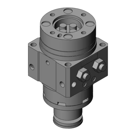
Product Description This Operation Manual is for the vane type rotary table. When using the product, load (moment of inertia), rotation time and other factors have to be considered. So, confirm the specification of the product prior to use. ■ How to Order (Basic type) M S U B 20 –... -
Page 19: Equivalent Sizes
■ Equivalent sizes Table 2 Correspondence to equivalent conventional free-mount type models Rotary table Free-mount rotary actuator MSUB 1 → CRBU2W10 MSUB 3 → CRBU2W15 MSUB 7 → CRBU2W20 MSUB 20 → CRBU2W30 ■ Product mass Table 3 Mass Basic mass Rotating Size Auto switch unit... -
Page 20: Allowable Load To The Table
■ Allowable Load to the table Set the load and moment to be applied to the table within the allowable values shown in the table below. (Values exceeding the allowable range will cause excessive play, reduce accuracy, and shorten service life.) Table 5 Allowable Load to the table Size... -
Page 21: Effective Torque
■ Effective torque... -
Page 22: Internal Construction And Components
Internal Construction and Components ■ Internal construction of rotary table For 90 Single vane Double vane For 180 (Pressure supplied to (Intermediate position (Pressure supplied to (Intermediate position) port A) for the 180 type) port A) Double vane: Size 1 Double vane: Size 3, 7, 20 Single vane: Size 1, 3, 7, 20 Table 6 Components... -
Page 23: Basic Circuit
Basic Circuit ■ Circuit configuration The standard circuit for operating a rotary actuator with an air filter, regulator, solenoid valve and speed controller is shown in Fig. 2 below. Rotary Speed Regulator Air filter actuator controller Mist separator Solenoid valve Fig. -
Page 24: Mounting
Mounting ■ Mounting for flange application L dimension when the unit is used as a flange is shown in the table below. When a hexagon socket head cap screw which complies to JIS is used, the screw head can be installed into the groove of the actuator. -
Page 25: Operating Environment
■ Operating environment Warning Do not use in environments where there is a danger of corrosion. Refer to "Internal Construction and Components" on page 5 for materials used for the rotary actuator. Never use this product in dusty locations or where water, oil, etc., splash on the equipment. ■... -
Page 26: Setting Of Rotation Time
Settings of Rotation Time Even if the torque that is required by the load in the rotation movement is small, the shaft or the internal parts could become damaged depending on the inertia of the load. Therefore, select an appropriate model for your application by taking the load’s moment of inertia, kinetic energy, and rotation time into consideration. -
Page 27: Calculation Formula For Moment Of Inertia
Calculation formulas for moment of inertia Moment of inertia (kg-m ), m: Load weight (kg) 1. Thin bar 6. Thin round disk Rotating shaft position: Perpendicular to the bar Rotating shaft position: On the diameter and goes along the center of gravity 2. -
Page 28: Kinetic Energy
Kinetic energy Allowable kinetic energy of MSUB series is shown in Table 10. The angular speed ω at the rotation ends can be found using the formula below. Table 10 Allowable kinetic energy Size Allowable kinetic energy (J) 0.005 0.013 : Rotating angle 0.032 :... -
Page 29: External Stopper
External stopper If the kinetic energy generated by the load exceeds the threshold value of the rotary table, an external dampening function must be provided to absorb the energy. ■ Mounting position of external stopper Rotating angle set with [OK] Mount an external stopper at just the external stopper below the center of gravity of the load,... -
Page 30: Calculation Of Necessary Torque
Calculation of Necessary Torque ■ Load type Table12 The calculation method for the torque required varies depending on the load type. Load type Static load: Ts Resistance load: Tf Inertial load: TA When only a pushing force is When gravity or friction force When rotating a load which has necessary (e.g. -
Page 31: Rotary Table With Auto Switch
Rotary Table with Auto Switch Rotary actuator with auto switch has a magnet mounted to the vane shaft, and an auto switch is mounted on the exterior of the body to detect the rotation position (magnet position). ■ How to Order (with auto switch) M D S U B 20 - 90 S - T79 With auto switch unit With auto switch unit... -
Page 32: Auto Switch Specification
■ Auto switch specification Table 14 Auto switch specifications Part No. Auto switch model Max. load current Model Application Load voltage Right Left Perpendicular Horizontal and load current handed handed entry entry range 24V AC/DC or D-90 Relay less 50mA 24 V AC/DC or Sequence controller less... -
Page 33: Internal Construction And Components
Internal Construction and Components ■ Construction of the rotary table with auto switch MDSUB1/ 3 MDSUB7/ 20 Table 15 Components Description Material Cover (A) Resin Cover (B) Resin Magnet lever Resin Holding block (A) Stainless steel Holding block (B) Aluminum alloy Holding block Stainless steel Switch block (A) -
Page 34: Internal Construction And Parts
■ Internal Construction and Parts MDSUB1/ 3 Table 16 MDSUB1/ 3 Description Material 1 Cover (A) Resin 2 Cover (B) Resin 3 Magnet lever Resin 4 Holding block (A) Aluminum alloy 5 Holding block (B) Aluminum alloy 7 Switch block (A) Resin 8 Switch block (B) Resin... -
Page 35: Mdsub1/3 Auto Switch Mounting Instruction
■ MDSUB1/3 Auto switch mounting instructions Auto switch unit/ Appearance and Parts descriptions Solid state switch Reed switch <Applicable auto switches> <Applicable auto switches> 3-wire type: D-S99(V), D-S9P(V) D-97, D-93A (with indicator light) 2-wire type: D-T99(V) D-90, D-90A (without indicator light) 1. -
Page 36: How To Move The Switch Detecting Position
■ How to move the switch detecting position When setting the detection position, loosen the holding screw to move the switch, and fix it at the required position by tightening the holding screw again. When doing it, if the set screw is tightened strongly, it will be broken and it will not be able to fix the screw, so keep the tightening torque to approximately 0.5 Nm. - Page 37 ■ ■ Rotation range of the table dowel pin hole and auto switch mounting position Fig. 10 Fig. 11 ・ In Fig. 9 and Fig. 10, the solid line arrows of the angle 90 degrees and 180 degrees show the rotation range of the dowel pin hole on the table.
-
Page 38: Operation Angle And Hysteresis Angle Of Auto Switch
■ Operation angle and hysteresis angle of auto switch [Example] Rotary table: 180 Switch operating angle: 90 When the switch is mounted at the intermediate position of the rotation As shown in the figure shown above, when the magnet rotates in the arrow direction along with the shaft rotation, the switch turns on when the magnet passes through the point A, and when it passes through the point B, the switch turns off. -
Page 39: Maintenance And Inspection
Maintenance and Inspection In order to use the rotary table in an optimal condition, it is necessary to perform maintenance depending on the operating conditions regularly. It is preferable to perform maintenance of the rotary table once a year in general, and it is strongly recommended that maintenance and repair are performed every three years. Note that if mechanical components such as vane shaft, bearing, etc. -
Page 40: Troubleshooting
Troubleshooting Problem Possible cause Countermeasure Supply pressure is not Correctly set the regulator applied correctly. at the supply pressure side. The directional switching Rotary table does Correctly apply a signal to the directional valve (such as a solenoid valve) not move. switching valve (such as a solenoid valve). - Page 41 must be adjusted in the position that it does not touch the stopper lever. 4. Check the load that is applied to the product, and modify the load to be within the allowable load range. Air leakage from the table Problem Possible cause Countermeasure...
- Page 42 Revision history A: Change to SI unit B: Double vane added C: Correction to "Safety Precautions" Tel: + 81 3 5207 8249 Fax: +81 3 5298 5362 https://www.smcworld.com Note: Specifications are subject to change without prior notice and any obligation on the part of the manufacturer. ©...
Need help?
Do you have a question about the 25A-MSUB Series and is the answer not in the manual?
Questions and answers