
Related Manuals for SMC Networks MHS2


Summary of Contents for SMC Networks MHS2
- Page 1 Doc.No.MH*-OMC0004 PRODUCT NAME 3 finger Air Gripper MODEL / Series / Product Number MHS2 MHS3 MHSJ3 MHSH3 MHSHJ3 MHS4...
- Page 2 Safety Instructions These safety instructions are intended to prevent hazardous situations and/or equipment damage. These instructions indicate the level of potential hazard with the labels of “Caution,” “Warning” or “Danger.” They are all important notes for safety and must be followed in addition to International Standards (ISO/IEC)*1) , and other safety regulations.
- Page 3 Safety Instructions Caution The product is provided for use in manufacturing industries. The product herein described is basically provided for peaceful use in manufacturing industries. If considering using the product in other industries, consult SMC beforehand and exchange specifications or a contract if necessary. If anything is unclear, contact your nearest sales branch.
-
Page 4: Table Of Contents
Contents Safety instructions 1. Product specifications ......................5 1-1. Specifications ........................5 2.Usage and Handling ........................ 7 2-1. Precautions on Design ......................7 2-2. Selection ..........................7 2-3.Mounting ..........................8 2-4. Air supply ........................... 14 2-5.Piping ..........................15 2-6. Operating environment ....................... 15 2-7. -
Page 5: Product Specifications
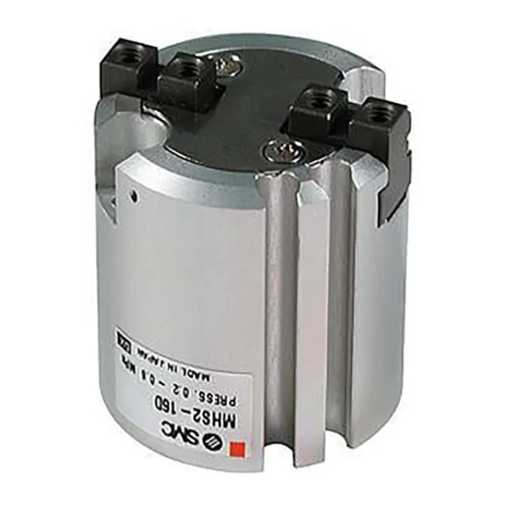
1. Product specifications 1-1. Specifications MHS2 Series Model MHS2-16D MHS2-20D MHS2-25D MHS2-32D MHS2-40D MHS2-50D MHS2-63D Cylinder bore size mm Fluid Operating pressure MPa 0.2 to 0.6 1.0 to 6.0 Ambient and fluid temperature deg. C -10 to 60 Repeatability mm +/- 0.01... - Page 6 MHSJ3 Series Model MHSJ3-16D MHSJ3-20D MHSJ3-25D MHSJ3-32D MHSJ3-40D MHSJ3-50D MHSJ3-63D MHSJ3-80D Cylinder bore size mm Fluid 0.2 to 0.6 0.1 to 0.6 Operating pressure MPa -10 to 60 Ambient and fluid temperature deg. C +/- 0.01 Repeatability mm Maximum operating frequency c.p.m Not required Lubrication Double acting...
-
Page 7: 2.Usage And Handling
2.Usage and Handling 2-1. Precautions on Design ! Warning 1. Provide a protective cover to minimize the risk of personal injury due to accidental contact with moving parts of the gripper or with moving work pieces. 2. Take measures to prevent an unexpected dropping of work pieces due to a loss of air pressure caused by service interruption or air supply failure. -
Page 8: 2-3.Mounting
4. Select model which has sufficient gripping force for the work piece weight. Incorrect selection may lead to dropping of work pieces, etc. Refer to the catalog for effective gripping force of each series and work piece weight. 5. Avoid applications where excessive external force or Impact acts. Such applications may cause failure. - Page 9 Mounting of Push Plate to Push Rod Use tightening torque in the table below and mount attachments by inserting bolts in female mounting thread of fingers. Female screws for push plate mounting Max. screw-in Max. tightening torque Model Bolt depth (mm) (N・m) MHSH(J)3-32DA M3×0.5...
- Page 10 Mounting of Air gripper Tapped hoes MHS2 Series Maximum screw- Max. tightening Model Screw in depth torque (N・m) (L mm) MHS2-16D M4×0.7 -20D M4×0.7 -25D M4×0.7 -32D M5×0.8 -40D M6×1 -50D M6×1 -63D M6×1 MHS3 Series Max. Maximum Use the hole at the body...
- Page 11 Axial mounting (Body tapped) MHSJ3,MHSH3 Series Maximum Max. screw-in tightening Model Screw depth torque (N・m) (L mm) MHSJ3-16D M4×0.7 MHSH3-16D MHSJ3-20D M4×0.7 MHSH3-20D MHSJ3-25D M4×0.7 MHSH3-25D MHSJ3-32D M4×0.7 MHSH3-32D M5×0.8 M4×0.7 MHSJ3-40D MHSH3-40D M5×0.8 M5×0.8 MHSJ3-50D MHSH3-50D M6×1 M6×1 MHSJ3-63D MHSH3-63D M8×1.25 M6×1...
- Page 12 Horizontal mounting (Body tapped) MHSJ3,MHSH3 Series(Senter pusher) Max. tightening Model Screw torque (N・m) MHS2 Series MHSH3-16DA Max. tightening M3x0.5 0.88 MHSH3-16DB Model Screw torque (N・m) MHSH3-20DA M3x0.5 0.88 MHS2-16D M3×0.5 0.88 MHSH3-20DB M3×0.5 0.88 MHSH3-25DA M3x0.5 0.88 NHSH3-25DB M3×0.5 0.88 MHSH3-32DA M4×0.7...
- Page 13 Caution 1. Avoid twisting the gripper when mounting an attachment. Any damage to the gripper may cause malfunction and reduce the accuracy. 2. Avoid external force to fingers. Fingers may be damaged by a continual lateral or impact load. Provide clearance to prevent the workpiece or the attachment from striking against any object at the stroke end.
-
Page 14: Air Supply
3. Adjust the gripping point so that an excessive force will not be applied to the fingers when inserting a workpiece. Confirm that the gripper can operate without receiving any shock by testing it in manual operation mode or by low speed operation. Good : With clearance Not Good : No clearance 4. -
Page 15: 2-5.Piping
2-5.Piping Caution 1. Refer to the Fittings and Tubing Precautions (Best Pneumatics) for handling one touch fittings. 2. Before piping Before piping is connected, flush thoroughly with air or wash to remove chips, cutting oil and other debris from inside the pipe. 2-6. -
Page 16: 3-2.Exploded View
Piston bolt O-ring for piston bolt Piston assembly (With packing and magnet) Piston packing Rod packing Body Finger End plate cross recessed countersunk head screw For MHS2 and MHS4, there are no major structural differences; refer to MHS3 for disassembly. - Page 17 MHSHJ3 Type C retaining ring O-ring for cap Cap (J) O-ring for cap Piston Rubber magnet Piston packing O-ring for piston Body Finger Fixing procedure for body and guide; Please use the parallel pin insertion holes on the body and guide. Positioning Cam (J) Packing for cam...
- Page 18 MHSJ3 Type C retaining ring Cap (A) O-ring for cap Piston Rubber magnet Piston packing O-ring for piston Body Finger Fixing procedure for body and guide; Please use the parallel pin insertion holes on the body and guide. Positioning pin Cam (A) End plate (A) cross recessed...
- Page 19 Center pusher/Cylinder type Center pusher/Spling type Type C retaining ring Cap (S) Push holder (P) Spring Damper O-ring for Hexagon socket Piston(P) piston Head cap screw Magnet Spring holder Damper Rod holder O-ring for Rod holder Push rod (S) Rod packing O-ring for push rod Push rod(P)
- Page 20 3-3. Replacement Procedure MHS3 1). Remove the C-shaped retaining ring 3). Remove the piston and replace the packing. with the prescribed tool and remove the cap. Type C retaining Piston ring Packing 4). Loosen cross recessed countersunk head screw and take out end plate. 2).
- Page 21 MHSJ3 1). Remove the dust cover (J). 4). Loosen cross recessed countersunk head screw and take out end plate. Cross recessed countersunk head screw End plate Dust cover (J) 5). Open the fingers and remove the cam. 2). Remove the C-shaped retaining ring with the prescribed tool and remove the cap.
- Page 22 MHSH3 1).Remove the c-shaped retaining ring with the 4). Open the fingers and remove the cam. specified tool and remove the cap. At that time, pull out the tube at the same time. Type C Retaining ring Finger 5). Loosen hexagon socket head cap screw 2).
- Page 23 Center pusher / Cylinder type 1). Remove the c-shaped retaining ring with the prescribed tool. Type C Retaining ring 2). Take out the push rod assembly and replace the packing. Packing Packing Push rod ASSY Packing ・When assembling, follow the reverse procedure. ・Refer to the exploded view for fastening torques of guide bolts and hexagon socket set screws.
- Page 24 3-4. Component parts/Parts list・Packing list MHS2,3,4 Component parts Parts name Material Note Body Aluminum alloy Hard anodized Piston Aluminum alloy Hard anodized Heat treated, Carbon steel Specially treated Heat treated, Finger Carbon steel Specially treated Aluminum alloy Hard anodized End plate...
- Page 25 MHSJ3 Component parts Parts name Material Note Body Aluminum alloy Hard anodized φ16 to φ25:stainless steel Piston φ32 to φ80: Aluminum alloy Hard anodized Heat treated, Cam(J) Carbon steel Specially treated Heat treated, Finger Carbon steel Specially treated Cap(J) Aluminum alloy Hard anodized End plate(J) stainless steel...
- Page 26 MHSH3 Component parts Parts Name Material Note Body Aluminum alloy Hard anodized φ16 to φ25:stainless steel Piston φ32 to φ80: Aluminum alloy Hard anodized Cam(A) Carbon steel Hard anodized Finger Carbon steel Hard anodized Cap(A) Aluminum alloy Hard anodized End plate(A) stainless steel Tubing stainless steel...
- Page 27 Replacement parts / Dust cover(A) Parts name Material Part no. MHSH3-32D MHSH3-40D MHSH3-50D MHSH3-63D MHSH3-80D MHSHJ3-32D MHSHJ3-40D MHSHJ3-50D MHSHJ3-63D MHSHJ3-80D Dust cover(A) Note)CR MHSHJ3-J32 MHSHJ3-J40 MHSHJ3-J50 MHSHJ3-J63 MHSHJ3-J80 MHSHJ3- MHSHJ3- MHSHJ3- MHSHJ3- MHSHJ3- Note)FKM J32F J40F J50F J63F J80F MHSHJ3- MHSHJ3- MHSHJ3- MHSHJ3-...
- Page 28 Center pusher/Spring type Component parts Parts Name Material Note Push holder(P) Aluminum alloy Hard anodized Cap(S) stainless steel Spring holder stainless steel Spring stainless steel Push rod(S) stainless steel Hard chromed Hexagon socket Zinc Carbon steel head cap acrew chromated Hexagon socket Zinc Carbon steel...
- Page 29 Revision history 4-14-1, Sotokanda, Chiyoda-ku, Tokyo 101-0021 JAPAN Tel: + 81 3 5207 8249 Fax: +81 3 5298 5362 https://www.smcworld.com Note: Specifications are subject to change without prior notice and any obligation on the part of the manufacturer. © 2023 SMC Corporation All Rights Reserved...
Need help?
Do you have a question about the MHS2 and is the answer not in the manual?
Questions and answers