Advertisement
Quick Links
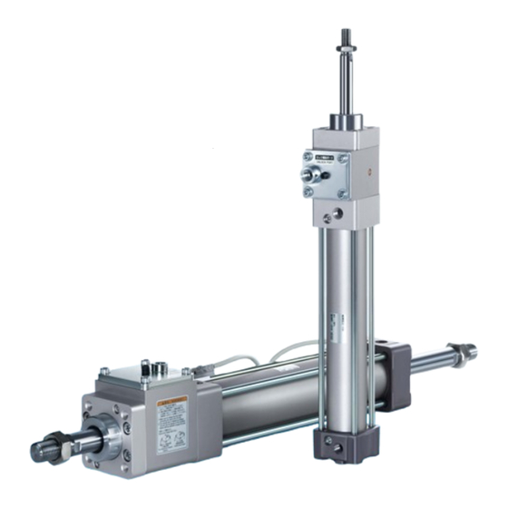
Cylinder with Lock
ø32, ø40, ø50, ø63, ø80, ø100
Lock can be manually operated with a hexagon wrench.
Can be easily mounted onto equipment
Locked state
Separable construction for improved ease of maintenance
The lock unit and the cylinder can be separated.
This allows for easier maintenance.
Lock unit
Holding force improved by
(MNB, ø50: 1370 N
a
High stopping accuracy within
(With ø50 and 30 kg of load)
Overall length reduced by
(Compared with an MNB, ø80, 100 mm stroke)
Lock Unit
Applicable for rod sizes ø12 to ø30
MWB
Series
Hexagon
wrench
Maintaining a manual lock
released state
Cylinder
15
MWB: 1570 N
)
1
±
18
mm
¡ Bore sizes ø80 and ø100 have been added.
¡ Lock units 80 and 100 have been added.
(Applicable rod size: ø25, ø30)
%
mm
max.
RoHS
CAT.ES20-246D
Advertisement

Related Manuals for SMC Networks MWB Series


Summary of Contents for SMC Networks MWB Series
- Page 1 Cylinder with Lock RoHS ø32, ø40, ø50, ø63, ø80, ø100 Lock can be manually operated with a hexagon wrench. Can be easily mounted onto equipment ¡ Bore sizes ø80 and ø100 have been added. ¡ Lock units 80 and 100 have been added. Hexagon wrench (Applicable rod size: ø25, ø30)
- Page 2 Cylinder with Lock Series A locking cylinder ideal for intermediate stops, emergency stops, and drop prevention Hexagon Overall length reduced by wrench Built-in manual lock release ¡ max. holding mechanism It is possible to release the ¡ Up to 18 mm shorter compared with the MNB series locked state with a hexagon Overall length wrench and hold the...
- Page 3 Cylinder with Lock Series The lock unit and the cylinder Compact auto switches are are separable in order to improve mountable. maintainability. ¡Solid state auto switch: D-M9 Lock unit ¡Reed auto switch: D-A9 Cylinder ¡Magnetic field-resistant auto switch: D-P3DWA Refer to page 42 for the replacement procedure. D-P4DW Lock Unit (page 32)
- Page 4 Cylinder with Lock Series Lock Unit A safety mechanism can be designed if required. It can also be combined with a wide variety of actuators. ¡Prevents the workpiece from falling Retains the workpiece position even when the air supply ¡ is shut off due to power failure, etc.
- Page 5 C O N T E N T S Cylinder with Lock Series Model Selection p. 5 ············································································································ MWB Series/Single Rod How to Order p. 7 ·················································································································· Specifications p. 8 ················································································································ Working Principle p. 10 ······································································································ Construction p. 11 ·················································································································...
- Page 6 Series Model Selection Step Find the maximum load speed V. Precautions on Model Selection Caution Find the maximum load speed: V [mm/s] from the load movement time: t [s] and the movement distance: st [mm]. 1. In order that the originally selected maximum speed shall not be exceeded, be certain to use a speed controller to adjust the Graph z total movement distance of the load so that movement takes...
- Page 7 Series Model Selection Selection Graph Graph x Graph b 0.3 MPa ≤ P < 0.4 MPa 0.3 MPa ≤ P < 0.4 MPa 1000 1000 ø100 ø100 ø80 ø80 ø63 ø63 ø100 ø100 ø50 ø50 ø80 ø80 ø40 ø40 ø63 ø63 ø32 ø32...
- Page 8 Cylinder with Lock Double Acting, Single Rod Series ø32, ø40, ø50, ø63, ø80, ø100 RoHS How to Order M9BW MDWB With auto switch With auto switch Bore size Number of auto Pivot bracket Auto switch switches (Built-in magnet) 32 mm No bracket Without auto switch 40 mm...
- Page 9 Cylinder with Lock Series Double Acting, Single Rod Cylinder Specifications Bore size [mm] Action Double acting, Single rod Fluid Proof pressure 1.5 MPa Max. operating pressure 1.0 MPa Min. operating pressure 0.08 MPa Ambient and fluid Without auto switch: −10°C to 70°C (No freezing) temperatures With auto switch: −10°C to 60°C...
- Page 10 Series Accessories Rod Boot Material Symbol Material Max. ambient temp. Axial Head Single Double Center Mounting Basic foot flange flange clevis clevis trunnion Nylon tarpaulin 70°C 110°C * Rod end nut Heat-resistant tarpaulin Standard Clevis pin —...
- Page 11 Cylinder with Lock Series Double Acting, Single Rod Working Principle Normal operation (Operation pressurized by air) Unlock port Unlock port (Apply air pressure.) (Exhaust the air.) Piston Seal washer Spring Piston taper Brake pad Piston rod Unlocked (when air pressure is applied) Locked (when air is exhausted) When air is supplied to the unlock port, the piston moves When the air supplied to the unlock port is exhausted, the...
- Page 12 Series Construction @1 @0 !8 !5 !6 !0 !1 @5 @8 #8 #6 #4 @4 @9 #0 #1 #3 #2 Component Parts Component Parts Description Material Qty. Note Description Material Qty. Note Brake unit Aluminum alloy Hard anodized Cushion valve Steel wire Zinc chromated Rolled steel...
- Page 13 Cylinder with Lock Series Double Acting, Single Rod Dimensions Basic: MWBB (Rc, NPT, G) Unlocked when pressurized (Rc, NPT, G) (Rc, NPT, G) Rod side cylinder port Head side cylinder port (Rc, NPT, G) Manual lock release bolt Cushion valve Width across flats ø...
- Page 14 Series Dimensions: With Mounting Bracket * Refer to Basic (B) for other dimensions. Axial foot: MWBL When the stroke is 2201 mm or longer, Port Cushion valve a tie-rod reinforcement ring is attached. 4 x ø + Stroke + Stroke With Rubber Bumper [mm] [mm]...
- Page 15 Cylinder with Lock Series Double Acting, Single Rod Dimensions: With Mounting Bracket * Refer to Basic (B) for other dimensions. Single clevis: MWBC Port Cushion valve When the stroke is 2201 mm or longer, a tie-rod reinforcement ring is attached. Hole dia.: + Stroke + Stroke...
- Page 16 Series Pivot Bracket: Trunnion and Double Clevis Pivot Bracket Part No. Bore size [mm] Trunnion pivot bracket * MB-S03 MB-S04 MB-S04 MB-S06 MB-S06 MB-S10 Double clevis pivot bracket MB-B03 MB-B03 MB-B05 MB-B05 MB-B08 MB-B08 *1 Order 2 trunnion pivot brackets per cylinder. Trunnion pivot bracket + 1/2 stroke 4 x ø...
- Page 17 Cylinder with Lock Series Double Acting, Single Rod Dimensions of Accessories Rod end nut Knuckle joint pin (Standard) Clevis pin 2 x ø [mm] [mm] Applicable Part no. Bore size Part no. Bore size (Drill through) split pin CD-M03 * NT-03 32, 40 M10 x 1.25...
- Page 18 Cylinder with Lock Double Acting, Double Rod MWBW Series ø32, ø40, ø50, ø63, ø80, ø100 RoHS How to Order MWBW M9BW MDWBW B With auto switch With auto switch Number of Pivot bracket Auto switch auto switches (Built-in magnet) Double rod No bracket Without auto switch Pivot bracket...
- Page 19 Cylinder with Lock MWBW Series Double Acting, Double Rod Cylinder Specifications Bore size [mm] Action Double acting, Double rod Fluid Proof pressure 1.5 MPa Max. operating pressure 1.0 MPa Min. operating pressure 0.08 MPa Ambient and fluid Without auto switch: −10°C to 70°C (No freezing) temperatures With auto switch: −10°C to 60°C...
- Page 20 MWBW Series Accessories Rod Boot Material Symbol Material Max. ambient temp. Axial Head Center Mounting Basic foot flange flange trunnion Nylon tarpaulin 70°C 110°C * Standard Rod end nut Heat-resistant tarpaulin Single knuckle joint ...
- Page 21 Cylinder with Lock MWBW Series Double Acting, Double Rod Construction @1 @0 !8 !5 !6 !0 !1 #7 #5 @8 $0 @4 @5 #0 #1 #9 9 9 #4 @7 !7 !2 #3 #2 Component Parts Component Parts Description Material Qty.
- Page 22 MWBW Series Dimensions Basic: MWBWB (Rc, NPT, G) Unlocked when pressurized (Rc, NPT, G) (Rc, NPT, G) Rod side cylinder port Head side cylinder port (Rc, NPT, G) Manual lock release bolt Cushion valve Width across flats ø Width across flats Thread depth Width across flats Width across flats...
- Page 23 Cylinder with Lock MWBW Series Double Acting, Double Rod Dimensions: With Mounting Bracket * Refer to Basic (B) for other dimensions. Axial foot: MWBWL Port Cushion valve 4 x ø + Stroke With Rubber Bumper [mm] [mm] LD LH LS Bore size Bore size 68.5...
- Page 24 MWBW Series Dimensions: With Mounting Bracket * Refer to Basic (B) for other dimensions. Head flange: MWBWG Port Cushion valve 4 x ø [mm] FB FD Bore size 24.5 29.5 35.5 38.5 Center trunnion: MWBWT + 1/2 stroke Port Cushion valve With Rubber Bumper [mm] [mm]...
- Page 25 Series Auto Switch Mounting Auto Switch Proper Mounting Position (Detection at stroke end) and Mounting Height <Tie-rod mounting> <Band mounting> D-M9 D-Y59 /Y69 /Y7P/Y7PV D-G39/K39/A3 D-M9 W/M9 D-Y7 W/Y7 WV/Y7BA D-M9 A/M9 D-Z7 /Z80 D-A9 ≈Hs ≈Hs Auto switch Auto switch D-A5 D-A44 D-A59W...
- Page 26 Series Auto Switch Proper Mounting Position (Detection at stroke end) and Mounting Height Auto Switch Proper Mounting Position [mm] Auto D-Y59m switch D-Y69m D-M9m model D-Y7P D-M9mV D-G39 D-F5m D-Y7PV D-M9mW D-A9m D-A5m D-K39 D-J59 D-F5NT D-A59W D-Y7H D-P3DWA D-P4DW D-M9mWV D-A9mV D-A6m...
- Page 27 Series Auto Switch Mounting Minimum Stroke for Auto Switch Mounting Mounting Brackets except Center Trunnion n: Number of auto switches [mm] Auto switch model Number of auto switches ø , ø , ø , ø ø ø 2 (Different surfaces, same surface) D-M9...
- Page 28 Series Minimum Stroke for Auto Switch Mounting Mounting Brackets except Center Trunnion n: Number of auto switches [mm] Auto switch model Number of auto switches , ø , ø , ø , ø ø ø 2 (Different surfaces, same surface) D-Y69...
- Page 29 Series Auto Switch Mounting Minimum Stroke for Auto Switch Mounting Center Trunnion n: Number of auto switches [mm] Auto switch model Number of auto switches ø32 ø40 ø50 ø63 ø80 ø100 2 (Different surfaces) 2 (Same surface) D-G39 60 + 30 (n – 2) 65 + 30 (n –...
- Page 30 Series Auto Switch Mounting Brackets/Part Nos. Bore size [mm] Auto switch model ø32 ø40 ø50 ø63 ø80 ø100 D-M9/M9V D-M9W/M9WV BMB5-032 BMB5-032 BA7-040 BA7-040 BA7-063 BA7-063 D-M9A/M9AV D-A9/A9V D-A3/A44 BMB2-032 BMB2-040 BMB1-050 BMB1-063 BMB1-080 BMB1-100 D-G39/K39 D-F5/J59 D-F5W/J59W D-F59F/F5BA BT-03 BT-03 BT-05 BT-05...
- Page 31 Series Auto Switch Mounting Other than the applicable auto switches listed in “How to Order,” the following auto switches are also mountable. Refer to the Web Catalog for the detailed specifications. Type Model Electrical entry Features D-M9NV/M9PV/M9BV — D-Y69A/Y69B/Y7PV D-M9NWV/M9PWV/M9BWV Diagnostic indication D-Y7NWV/Y7PWV/Y7BWV Grommet (Perpendicular)
- Page 32 Prior to Use Auto Switch Connections and Examples Sink Input Specifications Source Input Specifications 3-wire, NPN 3-wire, PNP Brown Input Brown Input Black Black Auto switch Auto switch Blue Blue (PLC internal circuit) (PLC internal circuit) 2-wire 2-wire Brown Input Brown Auto switch Auto switch...
- Page 33 Lock Unit MWB-UT Series 32, 40, 50, 63, 80, 100 RoHS How to Order With rod Mounting Made to order Basic Made to order individual specifications Axial foot (For details, refer to page 35-1.) Flange Symbol Specifications * Mounting bracket is shipped X3030...
- Page 34 MWB-UT Series Construction @1 @0 !7 !2 !5 !6 !0 !1 !8 Component Parts Description Material Qty. Note Description Material Qty. Note Brake unit Aluminum alloy Hard anodized 13 Hexagon socket head cap screw Alloy steel Rolled steel Zinc chromated 14 Hexagon socket head cap screw Alloy steel Collar...
- Page 35 MWB-UT Series Lock Unit Dimensions Basic: MWBB -UT- (Rc, NPT, G) Unlocked when pressurized (Rc, NPT, G) Manual lock release bolt Width across flats only 2 x 4 x Thread depth With rod [mm] Applicable KC MC Model rod size ø12 f8 38.5 46.5...
- Page 36 Series Made to Order Individual Specifications Please contact SMC for detailed dimensions, specifications, and lead times. Symbol Dimensionally Compatible with the MNB Series -X3000 MNB(W) series cylinders can easily be replaced with MWB(W) series cylinders. How to Order Cylinder Specifications Bore size X3000 Standard model no.
- Page 37 With lock status indication With coil scraper With coil scraper + cap nut * The model with a coil scraper is the same as the MWB-XC35. The specifications and dimensions are the same as those of the standard MWB series model. 35-1...
- Page 38 Caution Before operating the cylinder, be sure to first carry out a test operation to check for operation abnormalities as stated in the precautions in the MWB Series Operation Manual on the SMC website. 35-2...
- Page 39 Series Please contact your local sales Simple Specials representative for more details. The following changes are dealt with through the Simple Specials System. Symbol -XA0 XA30 Change of Rod End Shape Series Action Symbol for change of rod end shape Note Standard Double acting, Single rod...
- Page 40 Series Symbol: Symbol: Symbol: Symbol: 30° 30° 30° 30° Symbol: Symbol: Symbol: Symbol: øDA ∗ 30° ∗ 30° øDA LB K Symbol: Symbol: Symbol: 30° 30° 30° ∗ øDA...
- Page 41 Series Made to Order Common Specifications Please contact SMC for detailed dimensions, specifications, and lead times. Symbol With Coil Scraper -XC35 It gets rid of frost, ice, weld spatter, cutting chips adhered to the piston rod, and protects the seals, etc. Applicable Series How to Order Description...
- Page 42 When the overrun amount exceeds this range, cause damage to the lock mechanism. As the MWB series is self-holding of the contact should be performed at the equipped with a manual lock release mechanism, it is possible auto switch load side.
- Page 43 Series Specific Product Precautions 2 Be sure to read this before handling the products. Refer to the back cover for safety instruc- tions. For actuator and auto switch precautions, refer to the “Handling Precautions for SMC Products” and the “Operation Manual” on the SMC website: http://www.smcworld.com Mounting Adjustment Caution...
- Page 44 Series Specific Product Precautions 3 Be sure to read this before handling the products. Refer to the back cover for safety instruc- tions. For actuator and auto switch precautions, refer to the “Handling Precautions for SMC Products” and the “Operation Manual” on the SMC website: http://www.smcworld.com Pneumatic Circuit Manual Lock Release Warning...
- Page 45 Series Specific Product Precautions 4 Be sure to read this before handling the products. Refer to the back cover for safety instruc- tions. For actuator and auto switch precautions, refer to the “Handling Precautions for SMC Products” and the “Operation Manual” on the SMC website: http://www.smcworld.com Maintenance Caution 1.
- Page 46 Series Specific Product Precautions 5 Be sure to read this before handling the products. Refer to the back cover for safety instruc- tions. For actuator and auto switch precautions, refer to the “Handling Precautions for SMC Products” and the “Operation Manual” on the SMC website: http://www.smcworld.com Maintenance Caution 6) Confirm that the operation of 5) on the previous page is...
- Page 47 MWB -UT Series Specific Product Precautions 6 Be sure to read this before handling the products. Refer to the back cover for safety instruc- tions. For actuator and auto switch precautions, refer to the “Handling Precautions for SMC Products” and the “Operation Manual” on the SMC website: http://www.smcworld.com <Precautions for the lock unit MWB-UT>...
- Page 48 These safety instructions are intended to prevent hazardous situations and/or Safety Instructions equipment damage. These instructions indicate the level of potential hazard with the labels of “Caution,” “Warning” or “Danger.” They are all important notes for ∗1) safety and must be followed in addition to International Standards (ISO/IEC) and other safety regulations.
Need help?
Do you have a question about the MWB Series and is the answer not in the manual?
Questions and answers