Advertisement
Quick Links
www.leeandplumpton.co.uk
ASSEMBLY INSTRUCTIONS
RANGE
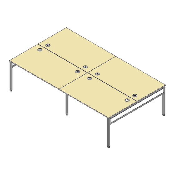
Libra Bench.
REF:
1200, 1400, 1600mm Wide.
Read this leaflet before
assembly
COMPONENT PARTS
Item 1
Item 2
M/0828 M/0829
NP10_0011
End Goal Post
End Goal Post Infill
Item 10
Top Panel & Rail Assembly
FIXINGS
Item 3
Item 4
F/0561
F/0655
M6x10mm Socket
M6 Lock Washer
Head Screw
Item 13
Item 15
A/1165
F/0414
Cable Port
5/8" Pan Posi Bzp
Screw
2 People
Required
Item 14
Cable Tray (Optional Item)
Item 5
Item 6
F/0433
F/0403
Minifix Bolt M6
Blum Cam Spigot
Item 8
M/0830 M/0831
Intermediate Goal Post
Item 7
Item 11
F/0419
F0532
5/8" x 8G Posi
Minifix Bolt Chipfast
Flange Black Screw
No. 119 A/2128 Revision A 15/08/2018
Item 9
Modesty Panel
Item 12
F.0436, F.0446, F.0545
F.0575, F.0576, F.0577
Cam Cover
1
Advertisement

Related Manuals for Lee & Plumpton Libra


Summary of Contents for Lee & Plumpton Libra
- Page 1 ASSEMBLY INSTRUCTIONS RANGE Libra Bench. REF: 1200, 1400, 1600mm Wide. 2 People Read this leaflet before Required assembly COMPONENT PARTS Item 1 Item 2 Item 8 Item 9 M/0828 M/0829 NP10_0011 M/0830 M/0831 Modesty Panel End Goal Post End Goal Post Infill...
-
Page 2: Tools Required
FIXINGS QUANTITIES BY PACK Packs Item 3 Item 4 Item 5 Item 6 Item 7 Item 11 Item 12 Item 13 Item 15 Bench End Goalposts Double Pack Bench Intermediate Goalpost Single Pack Top, Modesty Panel & Rail Pack (Bench) Cable Trays TOOLS REQUIRED BEFORE YOU BEGIN... - Page 3 ASSEMBLY INSTRUCTIONS STEP 3 Ensure that the M6x10mm Socket Head Screw (3) and the M6 Lock Washer (4) are unscrewed as far as possible whilst still being attached to the End Goalposts (1). This is to allow space for the ends of the Rails on the Top Panel &...
- Page 4 ASSEMBLY INSTRUCTIONS STEP 5 Connect the Goalpost (1) to the Modesty Panels (9). The end of the Modesty Panel (9) with the Blum Cam Spigots (6) fitted to it is the end which fits to the Cams in the infill panels of the End Goalposts (1) as shown.
-
Page 5: Care And Maintenance
ASSEMBLY INSTRUCTIONS STEP 8 If required, fit the Cable Trays (14) to the Modesty Panels (9), using the 5/8” Pan Posi BZP Screws (15) Fit Cable Tray to one in the pilot holes. side per 2 facing desks. Note Cable Trays are fitted to only one Modesty Panel per 2 facing desks.
Need help?
Do you have a question about the Libra and is the answer not in the manual?
Questions and answers