Table of Contents
Advertisement
Quick Links
www.leeandplumpton.co.uk
ASSEMBLY INSTRUCTIONS
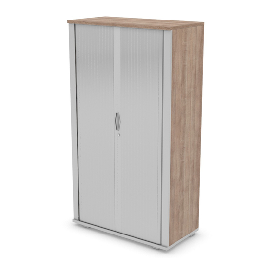
RANGE
Signature Storage, Tambour Units.
REF:
740mm High, 1000mm High, 1200mm High,
1600mm High, 1800mm High, 2000mm High
800mm and 1000mm Wide
Read this leaflet before
assembly
Item 1
STO1_780
Back Panel
Qty 1
Item 9
A.1807 or A.1808
Pilaster (Pelmet)
Qty 2
2 People
Required
Item 2
Item 3
STO1_844
STO1_788
Side Panel
LH Internal Side
Qty 2
Panel
Qty 1
Item 10
LH Tambour Door
Qty 1
Item 4
STO1_755
RH Internal
Side Panel
Qty 1
Item 11
RH Tambour Door
Qty 1
Item 5
STO1_592
Lintel
Qty 1
Item 6
STO1_762
Top Panel
Qty 1
Item 7
STO1_761
Bottom Panel
Qty 1
Item 12
A.1860
Track Corner
Qty 4
Item 13
A.1859
Track (392mm)
Qty 4
Item 14
A.1858
Track (374mm)
Qty 4
Item 15
A.1861
Track Centre Stop
Qty 2
A/1878 Revision A 29/01/2018
1
Advertisement
Table of Contents

Related Manuals for Lee & Plumpton Signature Tambour


Summary of Contents for Lee & Plumpton Signature Tambour
- Page 1 www.leeandplumpton.co.uk ASSEMBLY INSTRUCTIONS RANGE Signature Storage, Tambour Units. REF: 740mm High, 1000mm High, 1200mm High, 1600mm High, 1800mm High, 2000mm High 800mm and 1000mm Wide 2 People Read this leaflet before Required assembly COMPONENT PARTS Item 5 STO1_592 Lintel Qty 1 Item 6 STO1_762 Top Panel...
-
Page 2: Tools Required
COMPONENT PARTS Item 16 Item 17 Item 18 Item 19 Item 20 Item 21 Item 22 F.0629 F.0630 F.0431 F.0436, F.0446, F.0545, F.0401, F.0402, F.0403 F.0404A spreading Dowel (Blue) Rastex Cam Wood Dowel F.0575, F.0576, F.0577 F.0443, F.0489 Spigot For Blum Cam Kd Block Female (Brown) Qty, (See Table 1) Qty, (See Table 1) - Page 3 ASSEMBLY INSTRUCTIONS STEP 2 Assemble the two external Sides to the Back, lock the Cams with a half turn. STEP 3 Assemble the two internal Sides to the Back. Before locking the Cams in the Back, fit the Lintel (5) between the Sides. Ensure that the Lintel is fitted with the holes in its long edge facing out of the cabinet.
- Page 4 ASSEMBLY INSTRUCTIONS STEP 5 Attach the Top and Base to the Sides/Back/Lintel you built earlier. Screw on the Pilasters (9) with Screws (27). The Pilasters has a small groove running its length. Use this to place the tip of the screw appropriately for the number of screws supplied, with the same quantity used on both...
-
Page 5: Care And Maintenance
ASSEMBLY INSTRUCTIONS STEP 8 With the Door fully engaged in the top and bottom Tracks, turn it to be vertical. Slide the Door to the left into the cabinet and ensure it runs smoothly. With the left Door pushed back, repeat the installation of the right hand Door.
Need help?
Do you have a question about the Signature Tambour and is the answer not in the manual?
Questions and answers