Table of Contents
Advertisement
Quick Links
www.leeandplumpton.co.uk
ASSEMBLY INSTRUCTIONS
RANGE
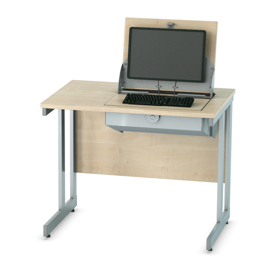
SmartTop
REF:
Single Desk
Read this leaflet before
assembly
COMPONENT PARTS
Item A
Item B
60mm Chipfast Bolt NP
Minifix Bolt M6
F/0486
F/0433
Qty 4
Qty 4
Item F
Item G
Minifix Cover Cap
Hole Plugs Grey 5mm
F/0545
A/0585
Qty 4
Qty 4
TOOLS REQUIRED
• Pozi head screwdriver
Minimum 200mm long
• T30 Allen Key (Supplied)
• 5mm Allen Key
IMPORTANT:
• Cables for the monitor and keyboard must not impede, or interfere with, the gas assisted strut as this could
damage the mechanism. Please ensure you use the cable clamps provided.
Please check the below details before attaching computer hardware:
• The maximum monitor size is 19 inches (486.2mm).
• Keyboard maximum dimensions 475mm wide x 40mm depth
• The overall weight of the complete item is 35kgs, apply manual handling guidelines.
• Only use component fixings supplied with this item.
• When closing monitor lid place hand in centre of the top to prevent trapping fingers or thumb and press
down until lid contacts latch.
2 People
Required
Item C
Wood Dowel
F/0431
Qty 2
BEFORE YOU BEGIN...
• Check you have all the tools and components required
• Keep children and animals away from small parts
• Ensure you have adequate space
• Assemble product on a flat, clean surface
• Apply manual handling guidelines when building this item
Item D
Item E
Minifix Alloy Cams 18mm
Adjustable Foot Black
F/0434
F/0606
Qty 4
Qty 4
No. 085 A/0944 Revision B 16/10/2019
1
Advertisement
Table of Contents

Related Manuals for Lee & Plumpton SmartTop Series


Summary of Contents for Lee & Plumpton SmartTop Series
- Page 1 www.leeandplumpton.co.uk ASSEMBLY INSTRUCTIONS RANGE SmartTop REF: Single Desk 2 People Read this leaflet before Required assembly COMPONENT PARTS Item A Item B Item C Item D Item E 60mm Chipfast Bolt NP Minifix Bolt M6 Wood Dowel Minifix Alloy Cams 18mm Adjustable Foot Black F/0486 F/0433...
- Page 2 ASSEMBLY INSTRUCTIONS STEP 1 STEP 4 STEP 7 Place top on a flat even surface. Screw part (B) into the holes of Apply part (F), cover cap, Place part (C) in appropriate holes over part (D). the upright on the cantilever legs in modesty panel.
Need help?
Do you have a question about the SmartTop Series and is the answer not in the manual?
Questions and answers