Table of Contents
Advertisement
Quick Links
MP144E
N472 Linear Actuator
User Manual
Version: 1.3.0
Physik Instrumente (PI) GmbH & Co. KG, Auf der Roemerstrasse 1, 76228 Karlsruhe, Germany
Phone +49 721 4846-0, Fax +49 721 4846-1019, Email info@pi.ws, www.pi.ws
Date: 29.10.2019
This document describes the following products:
N472.x10/.x10Y, N472.x1V/.x1VY
PiezoMike linear actuator, M10×1 thread
N472.x20/.x20Y, N472.x2V/.x2VY
PiezoMike linear actuator, 9.5 mm (0.375")
clamping shank
Models:
x represents the travel range:
1 = 7 mm
2 = 13 mm
Y: Turned cable exit
0: Not suitable for use in a vacuum
V: Vacuum-compatible to 10
-6
hPa
Advertisement
Table of Contents

Related Manuals for PI N-472. 10 Series


Summary of Contents for PI N-472. 10 Series
- Page 1 Y: Turned cable exit 0: Not suitable for use in a vacuum V: Vacuum-compatible to 10 Physik Instrumente (PI) GmbH & Co. KG, Auf der Roemerstrasse 1, 76228 Karlsruhe, Germany Phone +49 721 4846-0, Fax +49 721 4846-1019, Email info@pi.ws, www.pi.ws...
- Page 2 The patents held by PI are found in our patent list: http://www.physikinstrumente.com/en/about-pi/patents © 2019 Physik Instrumente (PI) GmbH & Co. KG, Karlsruhe, Germany. The text, photographs and drawings in this manual are protected by copyright. With regard thereto, Physik Instrumente (PI) GmbH & Co. KG retains all the rights.
-
Page 3: Table Of Contents
Contents About this Document Objective and Target Audience of this User Manual..........1 Symbols and Typographic Conventions..............1 Figures ........................2 Other Applicable Documents ..................2 Downloading Manuals ....................3 Safety Intended Use ......................5 General Safety Instructions ..................5 2.2.1 Organizational Measures ................ - Page 4 Maintenance Troubleshooting Customer Service Technical Data 10.1 Specifications ......................37 10.1.1 Data Table ....................37 10.1.2 Materials Used for Vacuum-Compatible Models ........39 10.1.3 Maximum Ratings ..................40 10.1.4 Ambient Conditions and Classifications ............40 10.2 Step Size and Axial Force ..................41 10.3 Lifetime ........................
-
Page 5: About This Document
1 About this Document About this Document In this Chapter Objective and Target Audience of this User Manual ..............1 Symbols and Typographic Conventions ..................1 Figures ............................2 Other Applicable Documents ......................2 Downloading Manuals ........................3 Objective and Target Audience of this User Manual This manual contains information necessary for the intended use of the N-472. -
Page 6: Figures
Photographic illustrations may also differ and must not be seen as guaranteed properties. Other Applicable Documents The devices and software tools from PI mentioned in this documentation are described in their own manuals. Description Document E-871.1A1N Compact PiezoMike - Q-Motion®... -
Page 7: Downloading Manuals
If a manual is missing or problems occur with downloading: Contact our customer service department (p. 35). Downloading manuals 1. Open the website www.pi.ws. 2. Search the website for the product number (e.g., N-472) or the product family (e.g., PiezoMike). -
Page 9: Safety
The intended use of the N-472 is only possible in conjunction with a suitable controller (p. 12), which is available from PI. The controller is not included in the scope of delivery of the N-472. The controller must provide the required operating voltages. It must also be able to read out and process the signals from the position sensors so that the servo control system can function properly. -
Page 10: Organizational Measures
Measures for Handling VacuumCompatible Products When handling the vacuum version of the linear actuator, attention must be paid to appropriate cleanliness. At PI, all parts are cleaned before assembly. During assembly and measurement, powder-free gloves are worn. Afterwards, the linear actuator is cleaned once again by wiping and shrink-wrapped twice in vacuum-compatible film. -
Page 11: Product Description
3 Product Description Product Description In this Chapter Model Overview ..........................7 Product View ..........................9 Product Labeling .......................... 11 Scope of Delivery ......................... 12 Suitable Controllers ........................12 Technical Features ........................13 Model Overview The models differ as follows: Travel range ... - Page 12 3 Product Description PiezoMike linear actuators with M10×1 thread Model Description N-472.110 Closed loop PiezoMike linear actuator, 7 mm, M10×1 thread N-472.110Y Closed loop PiezoMike linear actuator, 7 mm, M10×1 thread, turned cable exit N-472.210 Closed loop PiezoMike linear actuator, 13 mm, M10×1 thread N-472.210Y Closed loop PiezoMike linear actuator, 13 mm, M10×1 thread, turned cable exit PiezoMike linear actuators with M10×1 thread, vacuumcompatible to 10...
-
Page 13: Product View
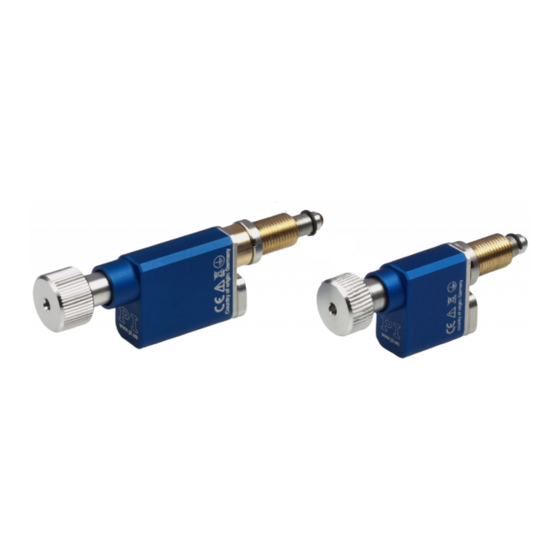
3 Product Description Product View N472 models with M10x1 thread The description of the product components is also valid for models with turned cable exit. Figure 1: Models with thread and standard cable exit (example illustration): Standard version (left) and vacuum version (right) Screw head Fine-threaded screw (rotating) Base body... - Page 14 3 Product Description N472 models with clamping shank The description of the product components is also valid for models with turned cable exit. Figure 2: Models with clamping shank and standard cable exit (example illustration): Standard version (left) and vacuum version (right) Screw head Fine-threaded screw (rotating) Base body...
-
Page 15: Product Labeling
3 Product Description Product Labeling Figure 4: N-472: Product labeling Figure 5: Type plate (N-472.110 as example) Figure 6: Laser marking (for vacuum-compatible models, N-470.41U as an example) N472 Linear Actuator MP144E Version: 1.3.0... -
Page 16: Scope Of Delivery
3 Product Description Position Labeling Description Manufacturer's logo WWW.PI.WS Manufacturer's address (website) CE conformity mark Warning sign "Pay attention to the manual!" Old equipment disposal (p. 51) Symbol for the protective earth conductor (p. 19) Country of origin: Germany Country of origin N-472.110... -
Page 17: Technical Features
(e.g., linear actuator type, serial number, date of manufacture, hardware version). When switched on or rebooted, controllers from PI read the data from the ID chip. For more information on the ID chip recognition, see the manual of the controller used. -
Page 19: Unpacking
INFORMATION When handling the vacuum version of the linear actuator, attention must be paid to appropriate cleanliness. At PI, all parts are cleaned before assembly. During assembly and measurement, powder-free gloves are worn. Afterwards, the linear actuator is cleaned once again by wiping and is then shrink-wrapped twice in vacuum-compatible film. -
Page 21: Installation
5 Installation Installation In this Chapter General Notes on Installation ...................... 17 Installing the Linear Actuator into a Mechanical Mounting and Connecting it to the Protective Earth Conductor ......................19 Preparing a Vacuum-Compatible N-472 for Connection to the Controller ......... 22 General Notes on Installation NOTICE Friction due to lateral forces! - Page 22 NOTICE Damage from unsuitable cables! Unsuitable cables can cause damage to the controller. Use cables from PI only to connect the N-472 to the controller. NOTICE Dirt, condensation, lubricants! Dirt, condensation and inappropriately applied lubricant render the drive inoperable.
-
Page 23: Installing The Linear Actuator Into A Mechanical Mounting And Connecting It To The Protective Earth Conductor
5 Installation Installing the Linear Actuator into a Mechanical Mounting and Connecting it to the Protective Earth Conductor INFORMATION The contact of the N-472 to the protective earth conductor is established via the contact of the mounting nut or thread or clamping shank to a sufficiently conductive mechanical mounting. The mechanical mounting must be connected to the protective earth conductor. - Page 24 5 Installation Figure 8: Models with clamping shank: Relevant components for installation into the mechanical mounting (example illustration) Clamping shank (9.5 mm diameter, 6 mm clamping width) M9×1 mounting nut Ball tip Figure 9: Two linear actuators on a mirror mount (example illustration) Linear actuators with mounting thread Mechanical mounting for linear actuators (fixed part of the mirror mounting) Mechanical mounting for mirror (movable part of the mirror mounting)
- Page 25 5 Installation You have provided a suitable mechanical mounting (for dimensions of the linear actuator see "Dimensions" (p. 45)): The mechanical mounting must be connected to the protective earth conductor. − The contact surface of the mechanical mounting to the mounting nut or thread or −...
-
Page 26: Preparing A Vacuum-Compatible N-472 For Connection To The Controller
5 Installation Installing an N472 with clamping shank 1. Optional: Apply a small amount of lubricant to the contact surface of the movable part of the mechanical mounting. 2. Remove the mounting nut from the clamping shank of the N-472. 3. - Page 27 5 Installation Assignment of the stranded wires and the cable shield Letter Wire color Function Signal Piezo voltage 0 to 80 V PIEZO+ Black Piezo voltage ground PIEZO- Exposed cable shield of the motor cable and the sensor cable Yellow Sensor signal, sine ENCA+ Green...
-
Page 29: Startup And Operation
Operating voltages that are too high or incorrectly connected can cause damage to the N-472. Operate the N-472 only with controllers/drivers and original accessories from PI. Do not exceed the operating voltage range (p. 40) for which the N-472 is specified. - Page 30 Operating frequency too high! An excessively high operating frequency can cause damage to the N-472. Operate the N-472 only with controllers/drivers and original accessories from PI. Do not exceed the operating frequency range (p. 40) specified for the N-472.
- Page 31 6 Startup and Operation NOTICE Increased wear due to friction! Increased friction on the contact surface between the ball tip and the movable part of the mechanical mounting increases wear. Make sure that the contact surface of the mechanical mounting has a roughness of R <0.1 µm and a hardness of at least 500 HV (corresponds to hardened steel).
-
Page 32: Operating Parameters
The entries in the positioner database are updated regularly. Install the PI Update Finder from the product CD of the controller onto your PC and update the positioner database on your PC. -
Page 33: Determining The Reference Position Manually
6 Startup and Operation Determining the Reference Position Manually You must determine the reference position manually in order to be able to perform positioning moves relative to a reference position. Requirements You have put the N-472 into operation (p. 28). ... - Page 35 7 Maintenance Maintenance When the N-472 is operated in a clean environment, no maintenance work is necessary. If you would like your device to be serviced, please contact our customer service department (p. 35). N472 Linear Actuator MP144E Version: 1.3.0...
- Page 37 8 Troubleshooting Troubleshooting Problem Possible causes Solution No or limited Check the connecting cables. The cable is not motion connected correctly or is defective Reduce the load. Pay attention to the Excessive information in the "Technical Data" section counterforces in (p.
- Page 39 9 Customer Service Customer Service For inquiries and orders, contact your PI sales engineer or send us an email (service@pi.de). If you have any questions concerning your system, provide the following information: Product and serial numbers of all products in the system −...
-
Page 41: Technical Data
10 Technical Data Technical Data In this Chapter Specifications ..........................37 Step Size and Axial Force ......................41 Lifetime ............................42 Operating Time and Duty Cycle ....................42 Dimensions ..........................45 Pin Assignment ..........................50 10.1 Specifications 10.1.1 Data Table Motion and N472.110 N472.11V... - Page 42 10 Technical Data Mechanical N472.110 N472.11V N472.210 N472.21V Unit properties N472.110Y N472.11VY N472.210Y N472.21VY N472.120 N472.12V N472.220 N472.22V N472.120Y N472.12VY N472.220Y N472.22VY Mechanical interface M10×1 M10×1 M10×1 M10×1 mounting mounting mounting mounting thread thread thread thread (N-472.110; (N-472.11V; (N-472.210; (N-472.21V; N-472.110Y) N-472.11VY) N-472.210Y)
-
Page 43: Materials Used For Vacuum-Compatible Models
10 Technical Data Miscellaneous N472.110 N472.11V N472.210 N472.21V Unit N472.110Y N472.11VY N472.210Y N472.21VY N472.120 N472.12V N472.220 N472.22V N472.120Y N472.12VY N472.220Y N472.22VY Cable length 1 m inside the 1 m inside the vacuum, bare vacuum, bare stranded stranded wires; wires; 2 m outside 2 m outside the vacuum, the vacuum,... -
Page 44: Maximum Ratings
10 Technical Data 10.1.3 Maximum Ratings N-472 linear actuators are designed for the following operating data: Model Maximum operating Maximum operating Maximum power voltage frequency during consumption continuous operation* N-472.xx0 80 V 400 Hz N-472.xx0Y N-472.xxV 80 V 200 Hz N-472.xxVY * Up to 2000 Hz is permissible for short periods of time. -
Page 45: Step Size And Axial Force
10 Technical Data 10.2 Step Size and Axial Force The following graph shows the step size of the N-472 against various axial forces. The influence of different axial forces on the step size is relatively minor. The active feed force is specified as 22 N (see "Technical Data"). -
Page 46: Lifetime
10 Technical Data 10.3 Lifetime The following graph shows the decrease in the step size over the lifetime of the N-472. The lifetime of the N-472 linear actuator is specified as 1 000 000 000 steps. Over this time, the typical step size decreases by maximum 30 %. - Page 47 10 Technical Data The following graph shows the operating time in seconds depending on the number of steps per second. Figure 13: Operating time in s vs. steps/s The following graph shows the duty cycle in % depending on the number of steps per second. Figure 14: Duty cycle in % vs.
- Page 48 10 Technical Data Vacuumcompatible models Number of steps Operating time Duty cycle (max.) / idle time per second* 2000 60 s (max.) 10 % / 9 min 2000 10 s 10 % / 90 s 1000 120 s (max.) 20 % / 8 min 1000 10 s 20 % / 40 s...
-
Page 49: Dimensions
10 Technical Data The following graph shows the duty cycle in % depending on the number of steps per second. Figure 16: Duty cycle in % vs. steps/s (vacuum versions of the N-472) 10.5 Dimensions Dimensions in mm. Note that a comma is used in the drawings instead of a decimal point. 10.5.1 Models with Turned Cable Exit INFORMATION... -
Page 50: Models With M10X1 Thread
10 Technical Data 10.5.2 Models with M10x1 Thread Figure 17: N-472.11x dimensions (* travel range) Version: 1.3.0 MP144E N472 Linear Actuator... - Page 51 10 Technical Data Figure 18: N-472.21x dimensions (* travel range) N472 Linear Actuator MP144E Version: 1.3.0...
-
Page 52: Models With Clamping Shank
10 Technical Data 10.5.3 Models with Clamping Shank Figure 19: N-472.12x dimensions (* travel range) Version: 1.3.0 MP144E N472 Linear Actuator... - Page 53 10 Technical Data Figure 20: N-472.22x dimensions (* travel range) N472 Linear Actuator MP144E Version: 1.3.0...
-
Page 54: Pin Assignment
10 Technical Data 10.6 Pin Assignment Dsub 15 connector (m) Figure 21: Front view of the D-sub 15 connector Signal Function Direction Not connected (reserved for reference switch, differential (-)) PIEZO- Motor signal (-) Input PIEZO+ Motor signal (+) Input Supply voltage +5 V Input Not connected... -
Page 55: Old Equipment Disposal
Dispose of your old equipment according to international, national, and local rules and regulations. In order to fulfil its responsibility as the product manufacturer, Physik Instrumente (PI) GmbH & Co. KG undertakes environmentally correct disposal of all old PI equipment made available on the market after 13 August 2005 without charge. - Page 57 12 EU Declaration of Conformity EU Declaration of Conformity For the N-472, an EU Declaration of Conformity has been issued in accordance with the following European directives: Low Voltage Directive EMC Directive RoHS Directive The applied standards certifying the conformity are listed below. Safety (Low Voltage Directive): EN 61010-1 EMC: EN 61326-1 RoHS: EN 50581...
Need help?
Do you have a question about the N-472. 10 Series and is the answer not in the manual?
Questions and answers