Table of Contents
Advertisement
Quick Links
MP144E
N-472 Linear Actuator
User Manual
Version: 1.5.0
Physik Instrumente (PI) GmbH & Co. KG, Auf der Römerstraße 1, 76228 Karlsruhe, Germany
Phone +49 721 4846-0, fax +49 721 4846-1019, e-mail info@pi.ws, www.pi.ws
Date: 29.09.2023
This document describes the following products:
N-472.110/.110Y, N-472.11V
PiezoMike linear actuator, 7 mm travel range,
M10×1 thread
N-472.120/.120Y, N-472.12V
PiezoMike linear actuator, 7 mm travel range,
9.5 mm (0.375") clamping shank
Models:
Y: Turned cable exit
0: Not suitable for use in a vacuum
V: Vacuum-compatible to 10
hPa
-6
Advertisement
Table of Contents

Related Manuals for PI N-472


Summary of Contents for PI N-472
- Page 1 Y: Turned cable exit 0: Not suitable for use in a vacuum V: Vacuum-compatible to 10 Physik Instrumente (PI) GmbH & Co. KG, Auf der Römerstraße 1, 76228 Karlsruhe, Germany Phone +49 721 4846-0, fax +49 721 4846-1019, e-mail info@pi.ws, www.pi.ws...
- Page 2 The patents held by PI are found in our patent list: https://www.physikinstrumente.com/en/about-pi/patents © 2023 Physik Instrumente (PI) GmbH & Co. KG, Karlsruhe, Germany. The text, photographs and drawings in this manual are protected by copyright. With regard thereto, Physik Instrumente (PI) GmbH & Co. KG retains all the rights.
-
Page 3: Table Of Contents
Installing the Linear Actuator into a Mechanical Mounting and Connecting it to the Protective Earth Conductor ................17 Preparing a Vacuum-Compatible N-472 for Connection to the Controller ....20 Starting and Operating General Notes on Starting and Operating ..............23 Operating Parameters .................... - Page 4 Maintenance Troubleshooting Customer Service Department Technical Data 10.1 Specifications ......................35 10.1.1 Data Table ....................35 10.1.2 Materials Used for Vacuum-Compatible Models ........37 10.1.3 Maximum Ratings ..................37 10.1.4 Ambient Conditions and Classifications ............38 10.2 Step Size and Axial Force ..................38 10.3 Lifetime ........................
-
Page 5: About This Document
Downloading Manuals ........................3 Objective and Target Audience of this User Manual This user manual contains the information required for using the N-472 as intended. It assumes that the reader has a fundamental understanding of basic servo systems as well as motion control concepts and applicable safety procedures. -
Page 6: Figures
For better understandability, the colors, proportions, and degree of detail in illustrations can deviate from the actual circumstances. Photographic illustrations may also differ and must not be seen as guaranteed properties. Other Applicable Documents The devices and software tools from PI mentioned in this documentation are described in separate manuals. Product Document E-873.1AT Q-Motion®... -
Page 7: Downloading Manuals
Contact our customer service department (p. 33). Downloading manuals 1. Open the website www.pi.ws. 2. Search the website for the product number (e.g., N-472). 3. Click the corresponding product to open the product detail page. 4. Click the Downloads tab. -
Page 9: Safety
General Safety Instructions......................5 Intended Use The N-472 is a laboratory device as defined by DIN EN 61010-1. It is intended for indoor use and use in an environment that is free from dirt, oil, and lubricants. The N-472 is a linear actuator for integration into mechanical and optomechanical components. -
Page 10: Organizational Measures
Add all information from the manufacturer such as supplements or technical notes to the user manual. If you give the N-472 to other users, include this user manual as well as all other relevant information provided by the manufacturer. -
Page 11: Product Description
Closed loop PiezoMike linear actuator, 7 mm, 9.5 mm (0.375") clamping shank, N-472.120Y turned cable exit PiezoMike linear actuators with clamping shank, vacuum-compatible to 10 Model Description Closed loop PiezoMike linear actuator, 7 mm, 9.5 mm (0.375") clamping shank, N-472.12V vacuum compatible to 10 N-472 Linear Actuator MP144E Version: 1.5.0... -
Page 12: Product View
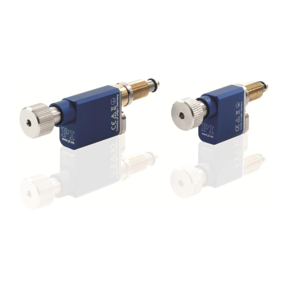
3 Product Description Product View N-472 models with M10x1 thread The description of the product components is also valid for models with turned cable exit. Figure 1: Models with thread and standard cable exit (example illustration): Standard version (left) and vacuum version (right) - Page 13 Cable for connecting to the controller (sensor cable not illustrated) Directions of Motion Figure 3: Directions of motion of the N-472 Pay attention to further information on the operating conditions in the "Technical Data" section (p. 35). N-472 Linear Actuator MP144E Version: 1.5.0...
-
Page 14: Product Labeling
3 Product Description Product Labeling Figure 4: N-472: Product labeling Figure 5: Type plate (N-472.110 as example) Figure 6: Laser inscription (for vacuum-compatible models, N-470.21V as an example) Version: 1.5.0 MP144E N-472 Linear Actuator... -
Page 15: Scope Of Delivery
Motor / sensor cable, D-sub 15 (m) to open end, 2 m, on the air side Suitable Controllers Product number Description E-873.1AT Q-Motion® controller for piezoelectric inertia drives, 1 axis, benchtop device (industry), SPI, TCP/IP, USB, RS-232, I/O, connector for joystick N-472 Linear Actuator MP144E Version: 1.5.0... -
Page 16: Technical Features
(e.g., linear actuator type, serial number, date of manufacture, hardware version). When switched on or rebooted, controllers from PI read the data from the ID chip. For more information on the ID chip recognition, see the manual of the controller used. -
Page 17: Unpacking
INFORMATION When handling the vacuum version of the linear actuator, attention must be paid to appropriate cleanliness. At PI, all parts are cleaned before assembly. During assembly and measurement, powder-free gloves are worn. Afterwards, the linear actuator is cleaned once again by wiping and is then shrink-wrapped twice in vacuum-compatible film. -
Page 19: Installing
Avoid lateral forces on the fine-threaded screw and on the ball tip of the N-472. Install the N-472 so that the fine-threaded screw is aligned vertically to the contact surface of the movable part of the mechanical mounting. - Page 20 Dirt, condensation and inappropriately applied lubricant render the drive inoperable. Keep the N-472 free from dirt and condensation. Do not remove the lubricant that was applied to the fine-threaded screw of the N-472 at the factory. Do not lubricate the fine-threaded screw of the N-472.
-
Page 21: Installing The Linear Actuator Into A Mechanical Mounting And Connecting It To The Protective Earth Conductor
Installing the Linear Actuator into a Mechanical Mounting and Connecting it to the Protective Earth Conductor INFORMATION The N-472 is connected to the protective earth conductor via a mounting nut, thread, or clamping shank fixed to a sufficiently conductive mechanical mounting. INFORMATION ... - Page 22 Mechanical mounting for mirror (movable part of the mirror mounting) Requirements You have read and understood the General Notes on Installation (p. 15). The N-472 is not connected to the controller. You have provided a suitable mechanical mounting that fulfills the following requirements: For models with mounting thread: An M10×1 through-hole is in the mechanical...
- Page 23 Installing an N-472 with mounting thread 1. Screw the mounting nut of the N-472 as far as necessary in the direction of the base body of the N-472. 2. Optional: Apply a small amount of lubricant to the contact surface of the movable part of the mechanical mounting.
-
Page 24: Preparing A Vacuum-Compatible N-472 For Connection To The Controller
5 Installing 4. Turn the mounting nut of the N-472 a few times by hand into the thread of the clamping shank. 5. Align the base body with the mechanical mounting. 6. Clamp the N-472 firmly in the mounting: −... - Page 25 Preparing a Vacuum-Compatible N-472 for Connection to the Controller 1. Attach the respective connectors for the vacuum feedthrough to the bare stranded wires of the N-472 cables on the vacuum side and on the air side: − Make sure that the stranded wires are assigned to each other as shown in the connection diagram.
-
Page 27: Starting And Operating
If the protective earth conductor is not or not properly connected, dangerous touch voltages can occur on the N-472 in the event of a malfunction or failure of the system. If there are touch voltages, touching the N-472 can result in serious injury or death from electric shock. - Page 28 Avoid lateral forces on the fine-threaded screw and on the ball tip of the N-472. Install the N-472 so that the fine-threaded screw is aligned vertically to the contact surface of the movable part of the mechanical mounting.
- Page 29 Stop the N-472 after reaching the end of the travel range or command motion away from the end of the travel range. If the N-472's fine-threaded screw gets stuck at the end of the travel range: Turn the head of the fine-threaded screw by hand to loosen it.
-
Page 30: Operating Parameters
The entries in the positioner database are updated regularly. Install the PI Update Finder from the product CD of the controller onto your PC and update the positioner database on your PC. -
Page 31: Determining The Reference Position Manually
6 Starting and Operating Operating the N-472 Follow the instructions for starting and operating the N-472 in the manual for the electronics (p. 11) used. Determining the Reference Position Manually You must determine the reference position manually in order to be able to perform positioning moves relative to a reference position. - Page 33 7 Maintenance Maintenance If the N-472 is operated in a clean environment, no maintenance is required. If you would like your device to be serviced, please contact our customer service department (p. 33). N-472 Linear Actuator MP144E Version: 1.5.0...
- Page 35 (p. 35). the direction of motion Load the parameter set from the positioner Parameters of the database that corresponds to the N-472 controller model. incorrectly set If necessary: In the PIMikroMove PC program, set the parameters of the...
- Page 37 9 Customer Service Department Customer Service Department For inquiries and orders, contact your PI sales engineer or send us an email (service@pi.de). If you have questions concerning your system, provide the following information: − Product and serial numbers of all products in the system −...
-
Page 39: Technical Data
Sensor signal Sin/cos, 1 V Sin/cos, 1 V Sin/cos, 1 V Sin/cos, 1 V Sin/cos, 1 V Sin/cos, 1 V peak-peak peak-peak peak-peak peak-peak peak-peak peak-peak N-472 Linear Actuator MP144E Version: 1.5.0... - Page 40 Cable length of vacuum-compatible models: 1 m connecting cable on the actuator, with stranded wires on the cable end; 2 m separate connecting cable, D-sub 15 (m) to stranded wires. Ask about customized versions. Version: 1.5.0 MP144E N-472 Linear Actuator...
-
Page 41: Materials Used For Vacuum-Compatible Models
10 Technical Data 10.1.2 Materials Used for Vacuum-Compatible Models The following materials were used for the vacuum-compatible models of the N-472: Component Material Stainless steel type 316L (1.4404) (housing) Machine-made parts Stainless steel type 301 (1.4310) (spring) Remaining parts: Vacuum-compatible lead-free bronze (drive component), rolling... -
Page 42: Ambient Conditions And Classifications
10.2 Step Size and Axial Force The following graph shows the step size of the N-472 against various axial forces. The influence of different axial forces on the step size is relatively minor. The active feed force is specified as 22 N (see "Technical Data"). -
Page 43: Lifetime
10.3 Lifetime The following graph shows the decrease in the step size over the lifetime of the N-472. The lifetime of the N-472 linear actuator is specified as >1,000,000,000 steps at ambient conditions (>50,000,000 steps under vacuum conditions). Over this time, the typical step size decreases by maximum 30 %. -
Page 44: Operating Time And Duty Cycle
10.4 Operating Time and Duty Cycle The operating time and duty cycle influence the lifetime of the N-472. In order to prevent overheating and strong wear, the operating time and the duty cycle must not exceed the values given in the following tables. The limit values depend on the following factors: Setting of the number of steps per second ... - Page 45 10 % / 90 s 1000 120 s (max.) 20 % / 8 min 1000 10 s 20 % / 40 s unlimited unlimited ≤200 * Set via the Maximum Motor Output operating parameter N-472 Linear Actuator MP144E Version: 1.5.0...
- Page 46 The following graph shows the operating time in seconds depending on the number of steps per second. Figure 15: Operating time in s vs. steps/s (vacuum versions of the N-472) The following graph shows the duty cycle in % depending on the number of steps per second. Figure 16: Duty cycle in % vs.
-
Page 47: Dimensions
The dimensional drawings in the subsequent sections show the N-472.xxx models with standard cable exit, but also apply to the N-472.xxxY models with turned cable exit. Take note: In the case of the N-472.xxxY models, the cable exit is located exactly opposite to the position shown in the dimensional drawings. -
Page 48: Models With M10X1 Thread
10 Technical Data 10.5.2 Models with M10x1 Thread Figure 17: N-472.11x dimensions (* travel range) Version: 1.5.0 MP144E N-472 Linear Actuator... -
Page 49: Models With Clamping Shank
10 Technical Data 10.5.3 Models with Clamping Shank Figure 18: N-472.12x dimensions (* travel range) N-472 Linear Actuator MP144E Version: 1.5.0... -
Page 50: Pin Assignment
Input Not connected Not connected (reserved for reference switch, differential (+)) ENCA+ Encoder channel A, differential (+) Output ENCB+ Encoder channel B, differential (+) Output The cable shield is connected to the connector shell. Version: 1.5.0 MP144E N-472 Linear Actuator... -
Page 51: Old Equipment Disposal
Dispose of your old equipment according to international, national, and local rules and regulations. To fulfill the responsibility as the product manufacturer, Physik Instrumente (PI) GmbH & Co. KG undertakes environmentally correct disposal of all old PI equipment made available on the market after 13 August 2005 without charge. - Page 53 12 European Declarations of Conformity European Declarations of Conformity For the N-472, declarations of conformity were issued according to the following European statutory requirements: Low Voltage Directive EMC Directive RoHS Directive The standards applied for certifying conformity are listed below.
Need help?
Do you have a question about the N-472 and is the answer not in the manual?
Questions and answers