Table of Contents
Advertisement
Quick Links
MP144E
N472 Linear Drive
User Manual
Version: 1.0.0
Physik Instrumente (PI) GmbH & Co. KG, Auf der Roemerstrasse 1, 76228 Karlsruhe, Germany
Phone +49 721 4846-0, Fax +49 721 4846-1019, Email info@pi.ws, www.pi.ws
Date: 02.03.2016
This document describes the following products:
N472.x10/.x10Y, N472.x1V/.x1VY
PiezoMike linear actuator, M10×1 thread
N472.x20/.x20Y, N472.x2V/.x2VY
PiezoMike linear actuator, 9.5 mm (0.375")
clamping shank
Models:
x represents the travel range:
1 = 7.5 mm
2 = 13 mm
Y: Offset cable exit
0: Not suitable for use in a vacuum
V: Vacuum-compatible to 10
-6
hPa
Advertisement
Table of Contents

Related Manuals for PI N-472 10 Series


Summary of Contents for PI N-472 10 Series
- Page 1 Y: Offset cable exit 0: Not suitable for use in a vacuum V: Vacuum-compatible to 10 Physik Instrumente (PI) GmbH & Co. KG, Auf der Roemerstrasse 1, 76228 Karlsruhe, Germany Phone +49 721 4846-0, Fax +49 721 4846-1019, Email info@pi.ws, www.pi.ws...
- Page 2 PI®, PIC®, PICMA®, PILine®, PIFOC®, PiezoWalk®, NEXACT®, NEXLINE®, NanoCube®, NanoAutomation®, Picoactuator®, PInano®, PIMag® © 2016 Physik Instrumente (PI) GmbH & Co. KG, Karlsruhe, Germany. The text, photographs and drawings in this manual are protected by copyright. With regard thereto, Physik Instrumente (PI) GmbH & Co. KG retains all the rights.
-
Page 3: Table Of Contents
Contents About this Document Objective and Target Audience of this User Manual..........1 Symbols and Typographic Conventions..............1 Figures ........................2 Other Applicable Documents ..................2 Downloading Manuals ....................3 Safety Intended Use ......................5 General Safety Instructions ..................5 2.2.1 Organizational Measures ................ - Page 4 Maintenance Troubleshooting Customer Service Technical Data 10.1 Specifications ......................39 10.1.1 Data Table ....................39 10.1.2 Materials Used for Vacuum-Compatible Models ........41 10.1.3 Maximum Ratings ..................41 10.1.4 Ambient Conditions and Classifications ............42 10.2 Step Size and Axial Force ..................43 10.3 Lifetime ........................
-
Page 5: About This Document
1 About this Document About this Document In this Chapter Objective and Target Audience of this User Manual ..............1 Symbols and Typographic Conventions ..................1 Figures ............................2 Other Applicable Documents ......................2 Downloading Manuals ........................3 Objective and Target Audience of this User Manual This manual contains information on the intended use of the N-472. -
Page 6: Figures
1 About this Document INFORMATION Information for easier handling, tricks, tips, etc. Symbol/Label Meaning Action consisting of several steps whose sequential order must be observed Action consisting of one or several steps whose sequential order is irrelevant List item ... -
Page 7: Downloading Manuals
4. Find the user name and the password in the section "User login for software download" in the Release News. Downloading Manuals 1. Open the website http://www.pi.ws. 2. Click Info. 3. If you have a user name and password: a) Click Login. -
Page 9: Safety
The intended use of the N-472 is only possible in conjunction with a suitable controller (p. 13), which is available from PI. The controller is not included in the scope of delivery of the N-472. The controller must provide the required operating voltages. It must also be able to read out and process the signals from the position sensors so that the servo-control system can function properly. -
Page 10: Organizational Measures
Measures for Handling VacuumCompatible Products When handling the vacuum version of the linear actuator, attention must be paid to appropriate cleanliness. At PI, all parts are cleaned before assembly. During assembly and measurement, powder-free gloves are worn. Afterwards, the linear actuator is cleaned once again by wiping and shrink-wrapped twice in vacuum-compatible film. -
Page 11: Product Description
3 Product Description Product Description In this Chapter Model Overview ..........................7 Product View ..........................9 Product Labeling .......................... 11 Scope of Delivery ......................... 12 Suitable Controllers ........................13 Technical Features ........................13 Model Overview The models differ in terms of the following features: Travel range ... - Page 12 3 Product Description PiezoMike linear actuators with M10×1 thread Model Description N-472.110 Closed-loop PiezoMike linear actuator, 7.5 mm, M10×1 mounting thread N-472.110Y Closed-loop PiezoMike linear actuator, 7.5 mm, M10×1 mounting thread, offset cable exit N-472.210 Closed-loop PiezoMike linear actuator, 13 mm, M10×1 mounting thread N-472.210Y Closed-loop PiezoMike linear actuator, 13 mm, M10×1 mounting thread, offset cable exit...
-
Page 13: Product View
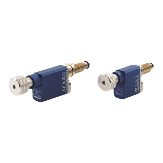
3 Product Description PiezoMike linear actuators with clamping shank, vacuumcompatible to 10 6 Model Description N-472.12V Closed-loop PiezoMike linear actuator, 7.5 mm, 9.5 mm (0.375") shank, vacuum-compatible to 10 Closed-loop PiezoMike linear actuator, 7.5 mm, 9.5 mm (0.375") shank, N-472.12VY vacuum-compatible to 10 hPa, offset cable exit N-472.22V... - Page 14 3 Product Description N472 models with clamping shank The description of the product components is also valid for models with offset cable exit. Figure 2: Models with clamping shank and standard cable exit (example illustration): Standard version (left) and vacuum version (right) Screw head Fine-thread screw (rotating) Base body...
-
Page 15: Product Labeling
3 Product Description Product Labeling Figure 4: N-472: Product labeling Figure 5: Type plate (N-472.110 as example) Figure 6: Laser marking (for vacuum-compatible models, N-470.41U as an example) N472 Linear Drive MP144E Version: 1.0.0... -
Page 16: Scope Of Delivery
3 Product Description Position Labeling Description Manufacturer's logo WWW.PI.WS Manufacturer's address (website) CE conformity mark Warning sign "Observe manual!" Old equipment disposal (p. 55) Symbol for the protective earth conductor (p. 19) Country of origin: Germany Country of origin N-472.110... -
Page 17: Suitable Controllers
(e.g., linear actuator type, serial number, date of manufacture, hardware version). When switched on or rebooted, controllers from PI read the data from the ID chip. For more information on the ID chip recognition, see the manual of the controller used. -
Page 19: Unpacking
INFORMATION When handling the vacuum version of the linear actuator, attention must be paid to appropriate cleanliness. At PI, all parts are cleaned before assembly. During assembly and measurement, powder-free gloves are worn. Afterwards, the linear actuator is cleaned once again by wiping and is then shrink-wrapped twice in vacuum-compatible film. -
Page 21: Installation
5 Installation Installation In this Chapter General Notes on Installation ...................... 17 Installing the Linear Actuator onto a Mechanical Mounting and Connecting it to the Protective Earth Conductor ......................19 Preparing the Vacuum-Compatible N-472 for Connection to the Controller ......23 General Notes on Installation NOTICE Friction due to lateral forces! - Page 22 NOTICE Damage from unsuitable cables! Unsuitable cables can cause damage to the controller. Only use cables from PI to connect the N-472 to the controller. NOTICE Dirt, condensation, lubricants! Dirt, condensation and inappropriately applied lubricant render the drive inoperable.
-
Page 23: Installing The Linear Actuator Onto A Mechanical Mounting And Connecting It To The Protective Earth Conductor
5 Installation NOTICE Damage to the finethread screw from contact with hard objects! Contact with hard objects can damage the thread of the fine-thread screw. A damaged thread can lead to the failure of the linear actuator. Prevent the fine-thread screw from coming into contact with hard objects. NOTICE Damage from overtightening the mounting nut! Overtightening the mounting nut can damage the linear actuator. - Page 24 5 Installation Figure 7: Models with thread: Relevant components for installation into the mechanical mounting (example illustration) M10×1 mounting nut Mounting thread Ball tip Figure 8: Models with clamping shank: Relevant components for installation into the mechanical mounting (example illustration) Clamping shank (9.5 mm diameter, 6 mm clamping width) M9×1 mounting nut Ball tip...
- Page 25 5 Installation Figure 9: Two linear actuators on a mirror mount (example illustration) Linear actuators with mounting thread Mechanical mounting for linear actuators (fixed part of the mirror mount) Mechanical mounting for mirror (moving part of the mirror mount) Requirements ...
- Page 26 5 Installation When lubricant is to be applied to the contact surface of the moving part of the mechanical mounting: Models that are not suitable for use in a vacuum: PTFE-based grease containing no additive Vacuum-compatible models: Vacuum-compatible PTFE-based grease containing no ...
-
Page 27: Preparing The Vacuum-Compatible N-472 For Connection To The Controller
5 Installation Preparing the VacuumCompatible N472 for Connection to the Controller To connect the vacuum version of the N-472, there are the following options: Use of a common vacuum feedthrough for motor cable and sensor cable Use of separate vacuum feedthroughs for motor cable and sensor cable ... - Page 28 5 Installation Figure 11: Vacuum-compatible N-472: Connections for motor cable and sensor cable when using separate vacuum feedthroughs 1. Vacuum-side connection for the motor cable of the N-472 2. Vacuum feedthrough for motor cable 3. Connection for motor cable from the scope of delivery of the N-472 4.
- Page 29 5 Installation Tools and accessories When using a common vacuum feedthrough (see corresponding connection diagram): − Suitable vacuum feedthrough for motor cable and sensor cable When using separate vacuum feedthroughs (see corresponding connection diagram): − Suitable vacuum feedthrough for motor cable −...
-
Page 31: Startup And Operation
Operating voltages that are too high or incorrectly connected can cause damage to the N-472. Only operate the N-472 with controllers/drivers and original accessories from PI. Do not exceed the operating voltage range (p. 41) for which the N-472 is specified. - Page 32 An operating frequency that is too high can cause damage to the N-472. Only operate the N-472 with controllers/drivers and original accessories from PI. Do not exceed the operating frequency range (p. 41) for which the N-472 is specified.
- Page 33 6 StartUp and Operation NOTICE Increased wear due to friction! Increased friction on the contact surface between the ball tip and the moving part of the mechanical mounting increases wear. Make sure that the contact surface of the mechanical mounting has a roughness of <0.1 µm and a hardness of at least 500 HV (corresponds to hardened steel).
-
Page 34: Operating Parameters
Observe further information on the operating conditions in the "Technical Data" section (p. 39). The N-472 is started up with the E-871 controller (p. 13) from PI. Operating Parameters If you use the software enclosed with the E-871 controller, the operating parameters can be loaded from the PIStages2.dat stage database. - Page 35 6 StartUp and Operation Operating the N472 Follow the instructions in the manual of the controller used for start-up and operation of the N-472. N472 Linear Drive MP144E Version: 1.0.0...
- Page 37 7 Maintenance Maintenance When the N-472 is operated in a clean environment, no maintenance work is necessary. If you would like your device to be serviced, please contact our customer service department (p. 37). N472 Linear Drive MP144E Version: 1.0.0...
- Page 39 8 Troubleshooting Troubleshooting Problem Possible causes Solution No or limited Check the connecting cables. Cable not motion connected correctly or defective Reduce the load. Observe the information Excessive in the "Technical Data" section (p. 39). counterforces in the direction of motion ...
- Page 41 9 Customer Service Customer Service For inquiries and orders, contact your PI sales engineer or send us an e-mail (info@pi.ws). If you have questions concerning your system, have the following information ready: − Product codes and serial numbers of all products in the system −...
-
Page 43: Technical Data
10 Technical Data Technical Data In this Chapter Specifications ..........................39 Step Size and Axial Force ......................43 Lifetime ............................44 Operating Time and Duty Cycle ....................44 Dimensions ..........................48 Pin Assignment ..........................53 10.1 Specifications 10.1.1 Data Table N472.110 N472.11V N472.210... - Page 44 10 Technical Data N472.110 N472.11V N472.210 N472.21V Unit N472.110Y N472.11VY N472.210Y N472.21VY N472.120 N472.12V N472.220 N472.22V N472.120Y N472.12VY N472.220Y N472.22VY Maximum permissible operating frequency during continuous operation Mechanical Properties Holding force, >100 >100 >100 >100 de-energized Feed force Drive Properties Drive type PIShift piezo PIShift piezo...
-
Page 45: Materials Used For Vacuum-Compatible Models
10 Technical Data 10.1.2 Materials Used for VacuumCompatible Models Materials used for vacuumcompatible models Machine-made parts Stainless steel type 316L (1.4404) (casing) Stainless steel type 301 (1.4310) (spring) Remaining parts: Vacuum-compatible lead-free bronze (drive component), rolling bearing steel (ball tip), stainless steel (mounting screws), spring steel (circlip) Drive elements Stainless steel (fine-thread screw) -
Page 46: Ambient Conditions And Classifications
10 Technical Data 10.1.4 Ambient Conditions and Classifications The following ambient conditions and classifications for the N-472 must be observed: Area of application For indoor use only Maximum altitude 2000 m Air pressure Models N-472.xx0 and N-472.xx0Y: 1100 hPa to 0.1 hPa Models N-472.xxV and N-472.xxVY: 1100 hPa to 10 hPa (high vacuum) -
Page 47: Step Size And Axial Force
10 Technical Data 10.2 Step Size and Axial Force The following graph shows the step size of the N-472 against various axial forces. The influence of different axial forces on the step size is relatively minor. The active feed force is specified as 22 N (see "Technical Data"). -
Page 48: Lifetime
10 Technical Data 10.3 Lifetime The following graph shows the decrease in the step size over the lifetime of the N-472. The lifetime of the N-472 linear actuator is specified as 1 000 000 000 steps. Over this time, the typical step size decreases by maximum 30 %. - Page 49 10 Technical Data Models that are not suitable for use in a vacuum Number of steps Operating time Duty cycle (max.) / idle time per second* 2000 60 s (max.) 20 % / 4 min 2000 10 s 20 % / 40 s 1000 120 s (max.) 40 % / 180 s...
- Page 50 10 Technical Data The following graph shows the duty cycle in % depending on the number of steps per second. Figure 15: Duty cycle in % vs. steps/s Vacuumcompatible models Number of steps Operating time Duty cycle (max.) / idle time per second* 2000 60 s (max.)
- Page 51 10 Technical Data The following graph shows the operating time in seconds depending on the number of steps per second. Figure 16: Operating time in s vs. Steps/s (vacuum versions of the N-472) The following graph shows the duty cycle in % depending on the number of steps per second. Figure 17: Duty cycle in % vs.
-
Page 52: Dimensions
10 Technical Data 10.5 Dimensions Dimensions in mm. Note that the decimal places are separated by a comma in the drawings. 10.5.1 Models with Offset Cable Exit INFORMATION The dimensional drawings in the subsequent sections show the N-472.xxx models with standard cable exit, but also apply to the N-472.xxxY models with offset cable exit. -
Page 53: Models With M10X1 Thread
10 Technical Data 10.5.2 Models with M10x1 Thread Figure 18: Dimensions N-472.11x (* stroke) N472 Linear Drive MP144E Version: 1.0.0... - Page 54 10 Technical Data Figure 19: Dimensions N-472.21x (* stroke) Version: 1.0.0 MP144E N472 Linear Drive...
-
Page 55: Models With Clamping Shank
10 Technical Data 10.5.3 Models with Clamping Shank Figure 20: Dimensions N-472.12x (* stroke) N472 Linear Drive MP144E Version: 1.0.0... - Page 56 10 Technical Data Figure 21: Dimensions N-472.22x (* stroke) Version: 1.0.0 MP144E N472 Linear Drive...
-
Page 57: Pin Assignment
10 Technical Data 10.6 Pin Assignment HD SubD connector, 15pin, male Figure 22: Motor connector: Front view of the HD Sub-D 15-pin connector (m) Signal Function PIEZO_V- Piezo voltage for PIShift inertia drive Input (GND) 2 to 5 Not connected Piezo_V+ Piezo voltage for PIShift inertia drive Input... - Page 58 10 Technical Data Signal Function Not connected Not connected Not connected COS_N_C Encoder B (-) Output SIN_N_C Encoder A (-) Output IDCHIP_IO_C ID chip Bidirectional VDD_SWITCHED Input Supply voltage for encoder Not connected Not connected Version: 1.0.0 MP144E N472 Linear Drive...
-
Page 59: Old Equipment Disposal
Dispose of your old equipment according to international, national, and local rules and regulations. In order to fulfil its responsibility as the product manufacturer, Physik Instrumente (PI) GmbH & Co. KG undertakes environmentally correct disposal of all old PI equipment made available on the market after 13 August 2005 without charge. - Page 61 12 EC Declaration of Conformity EC Declaration of Conformity For the N-472, an EC Declaration of Conformity has been issued in accordance with the following European directives: Low Voltage Directive EMC Directive RoHS Directive The applied standards certifying the conformity are listed below. Safety (Low Voltage Directive): EN 61010-1 EMC: EN 61326-1 RoHS: EN 50581...
Need help?
Do you have a question about the N-472 10 Series and is the answer not in the manual?
Questions and answers