Table of Contents
Advertisement
Quick Links
Advertisement
Table of Contents

Related Manuals for OSEE LCM156-A


Summary of Contents for OSEE LCM156-A
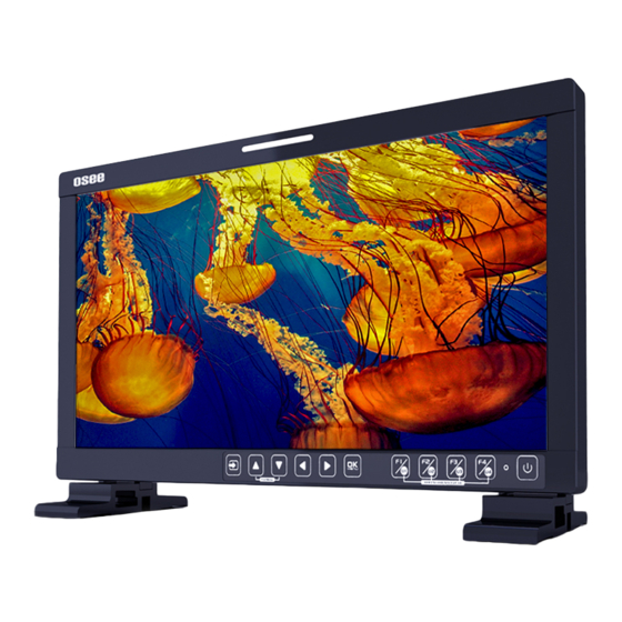
- Page 1 LCM156-A LCM215-A LCD Monitor User Manual...
- Page 3 Product Information Model: LCM156-A LCM215-A LCD Monitor Version: V010000 August Release Date: Company OSEE TECHNOLOGY LTD. Contact Information No.22 Building, No.68 zone, Beiqing Road, Haidian District, Address: Beijing, China 100094 Post Code: Tel: (+86) 010-62434168 Fax: (+86) 010-62434169 http://www.osee-dig.com/ Web: E-mail: sales@osee-dig.com...
-
Page 4: Contents
The user manual applies to the following device types: LCM156-A LCM215-A The images of LCM156-A are adopted in the following descriptions. Any of the different specifications between the device types are elaborated. Before reading the manual, please confirm the device type. -
Page 5: Table Of Contents
Contents Contents ......................I Chapter 1 Overview ..................1 Chapter 2 Safety ..................... 3 Chapter 3 Unpack and Installation ............... 7 Chapter 4 Locations and Function of Parts and Control ......11 4.1 Front Panel ..................12 4.1.1 Arrangement of Front Panel ............12 4.1.2 Input Selection ................ -
Page 7: Chapter 1 Overview
By adopting the advanced 10-bit digital signal processing technology plus 3D comb filter, de-interlacing capability and accurate scaling ensures the LCM156-A LCD Monitor to achieve a better effect of smoother and more natural image. The LCM156-A LCD Monitor supports up to 2Ch 3G/HD/SD-SDI inputs, 1Ch VIDEO input, one HDMI input and 1Ch 3G/HD/SD-SDI output. - Page 8 Overview Features Prevailing slim bezel design Having multi format input including 3G/HD/SD-SDI, VIDEO and HDMI Adopting full HD, wide viewing angle TFT glass Using 10-bit signal processing technology plus advanced conversion technology between the interlacing and the progressive ...
-
Page 9: Chapter 2 Safety
Safety Chapter 2 Safety FCC Caution Any Changes or modifications not expressly approved by the party responsible for compliance could void the user's authority to operate the equipment. This device complies with part 15 of the FCC Rules. Operation is subject to the following two conditions: (1) This device may not cause harmful interference, and (2) this device must accept any interference received, including interference that may cause undesired operation. - Page 10 Safety Warnings: Read, keep and follow all of these instructions for your safety. Heed all warnings. Device Install in accordance with the manufacturer's instructions. Do not beat with a hard object or scratch the LCD display. Do not make the freeze picture displaying on the screen time too long, otherwise, it will leave the afterimage on the screen.
- Page 11 Safety heat. A nameplate indicating operating voltage, etc., is located on the rear panel. The socket-outlet shall be installed near the equipment and shall be easily accessible. Power Supply Cord Do not defeat the safety purpose of the polarized or grounding-type plug.
-
Page 13: Chapter 3 Unpack And Installation
Chapter 3 Unpack and Installation Unpack: When unpacking the components of LCM156-A monitor, please verify that none of the components listed in Table 3.1 are damaged or lack. If there is any missing, contact your distributors or OSEE Technology Ltd. for it. - Page 14 Unpack and Installation Figure 3-1 Stands Assembly Figure 3-2 Stands for LCM156-A Connect required cables for signal input and output. For BNC connections use 75Ω rated connectors. Connect 100~240V50/60Hz AC or 11~17V3A DC power source using the power cord, or 11~16.8V DC camera battery(with optional battery plate).
- Page 15 Unpack and Installation The pedestal and the monitor are packaged separately. Connect a standard signal line to the corresponding input port. All BNC connector impedance must be 75Ω. Please use the power cord supplied to avoid unnecessary trouble.
-
Page 17: Chapter 4 Locations And Function Of Parts And Control
Chapter 4 Locations and Function of Parts and Control This chapter describes the features of LCM156-A monitor. The features of LCM156-A monitor are as shown in Figure 4-1 after installed and powered Figure 4-1 Features of LCM156-A Monitor Status Information The Status Information is displayed in the top left corner of the screen, and includes the input channel and signal format. -
Page 18: Front Panel
Locations and Function of Parts and Control display it or not and their displaying mode in USER CONFIG menu Center Marker It is displayed in the center of the screen, and marks the center of the image. You can set whether to display it or not in USER CONFIG menu. - Page 19 Locations and Function of Parts and Control Figure 4.1-1 the Buttons in Front Panel As shown in Figure 4.1-1, the buttons of LCM156-A are as follows: BUTTON FUNCTION COMMENTS Input selection Used to switch an input signal 1. It is UP button when working with the main menu.
-
Page 20: Input Selection
Locations and Function of Parts and Control BUTTON FUNCTION COMMENTS Turn Page: when the current selection in the sub-menu list is Next Page, press this button to turn to the next page circularly. 2. With the Fast menu: when displaying the Fast menu, press RIGHT button to increase the item value. -
Page 21: Main Menu On/Off
Locations and Function of Parts and Control Figure 4.1-2 Source Menu 4.1.3 Main Menu ON/OFF Display the Main menu: press OK/MENU button to activate the main menu at the center of the screen, as shown in Figure 4.1-3. Close the Main men: press LEFT button to quit the displayed Main menu. -
Page 22: Function Menu & User Preset
Locations and Function of Parts and Control After displaying the Fast Menu, press LEFT or RIGHT arrow button to adjust the menu value. The limitations of these items are shown in Table 4.1-1: Table 4.1-1 The Description of Fast Menu Items Adjust Menu Description Range... -
Page 23: Rear Panel
4.2.1 Arrangement of Rear Panel For the arrangement of the rear panel of LCM156-A is shown in Figure 4.2-1, there are various input and output interfaces at the rear panel, and build-in speakers in the top. - Page 24 Locations and Function of Parts and Control Figure 4.2-1 Connectors in the Rear Panel The interfaces numbered in red are described as follows: Interface Comments Push the button to the direction “-” to switch on the power, or Power Switch push the button to the direction “O”...
-
Page 25: Power On
RS485 Terminal Signal 4.2.2 Power On Power Method There are three methods for powered LCM156-A as below: Method 1: Powered by AC power input. Connect external power through the AC IN interface. (100~240V50/60HzAC) Method 2: Powered by DC power input. Connect external power through the DC IN interface. -
Page 26: Supported Signal Format
Locations and Function of Parts and Control Power Indicator The power indicator is besides the POWER button. If the light is green, the monitor is powered on, and if the light is red, the monitor is standby. Only use the adapter and the power cord specified by the manufacture for your safety!... - Page 27 Locations and Function of Parts and Control Signal HDMI VIDEO 1080P25 1080P30/29.97 1080I50 4:2:2 YCbCr 12 BIT 4:4:4 YCbCr 10 BIT 1080I60/59.94 4:4:4 YCbCr 12 BIT 1080P24/23.98 4:4:4 RGB 10 BIT 4:4:4 RGB 12 BIT ...
-
Page 29: Chapter 5 Menu Operations
Menu Operations Chapter 5 Menu Operations This chapter describes the structure and functionality of the main menu, and introduces how to modify and customize the menu settings. The main menu includes the following menu items, as shown in Figure5-1. Figure 5-1 Main Menu 5.1 Main Menu Press the OK/MENU button at the bottom of the front panel, the main menu is displayed at the center of the screen, as shown in Figure 5.1-1:... - Page 30 Menu Operations The menu interface is divided into three parts: Main Menu List It contains the menu list of the Main menu. Press UP or DOWN to access the corresponding menu item. Sub-menu list Press right arrow button to enter into the next level of menu list, as shown in Figure 5.1-2, it lists the title of the Sub-menu, the sub-menu item and the value of the item.
-
Page 31: Status Menu
Menu Operations The following will introduce the contents and functionality of these sub-menu items in sorts. 5.1.1 STATUS Menu The STATUS menu items are used to describe the current status information of the monitor, the menu items are as shown in Figure 5.1-3: Figure 5.1-3 STATUS Menu There are two pages in STATUS menu. -
Page 32: Input Config Menu
Menu Operations Items Default Value Description Camera LUT Type Camera SDR Show the type of camera LUT User Preset USER1 Show the user preset name Page2 Model Show the production model. Serial Number Show the serial number. Firmware Version Show the firmware number. ... -
Page 33: Color Management Menu
Menu Operations Default Items Domain Range Description Value Page1 SDI IN1 ON/OFF Enable/Disable SDI1 input SDI IN2 ON/OFF Enable/Disable SDI2 input VIDEO ON/OFF Enable/Disable VIDEO input HDMI ON/OFF Enable/Disable HDMI input Set the NTSC phase level, and this item is available only NTSC Phase 0 -50~50 when NTSC format signal is... - Page 34 Menu Operations shown in Figure 5.1-5: Figure 5.1-5 COLOR MANAGEMENT Menu There are two pages in COLOR MANAGEMENT menu. The relationship of Items, Default Value, Domain Range and Description of the sub-item is shown in Table 5.1-4: Table 5.1-4 The Description of COLOR MANAGEMENT Menu Items Default Items Domain Range...
- Page 35 Load a customized LUT file To load a LUT file from the U Load LUT File --- disk Camera LUT The LCM156-A supports multiple camera LUTs, as shown in Table 5.1-5: Table 5.1-5 The Relationship Between EOTF and HDR Camera LUT LUT Name Company...
- Page 36 Sony Sony_SLog3SG3Cine_LCRec709 Sony_SLog3SG3Cine_LCRec709A ARRI_LogC_HLG_Rec2020 ARRI_LogC_PQ_Rec2020 Canon_Clog2Cin_HLG_Rec2020 Canon_Clog2Cin_PQ_Rec2020 Canon_Clog3Cin_HLG_Rec2020 Canon_Clog3Cin_PQ_Rec2020 Panasonic_VLog_HLG_Rec2020 OSEE Panasonic_VLog_PQ_Rec2020 RED_L3G10_HLG_Rec2020 RED_L3G10_PQ_Rec2020 Sony_SLog3_Cin_HLG_Rec2020 Sony_SLog3_Cin_PQ_Rec2020 Sony_SLog3_SG3_HLG_Rec2020 Sony_SLog3_SG3_PQ_Rec2020 When setting Camera LUT Type item as Camera SDR, Camera HDR or User, the following corresponding Camera SDR, Camera HDR, User item will be activated, and the available ranges of Gamma are...
- Page 37 Menu Operations diverse, as shown in the following table: Camera LUT Type Gamma Camera SDR 1.8/2.2/2.4/2.6/2.8/BT.1886 Camera HDR PQ/HLG User or OFF 1.8/2.2/2.4/2.6/2.8/BT.1886/PQ/HLG Load a user LUT from disk First, load a LUT file to the designated user LUT. Set COLOR Management...
-
Page 38: User Config Menu
Menu Operations TEMPRESET command to restore product originals for Gains, and press OK/MENU button to confirm the reset operation. 5.1.4 USER CONFIG Menu The USER CONFIG menu items are used to adjust the parameters defined by customers, the menu items are as shown in Figure 5.1-7: Figure 5.1-7 CONFIG Menu There are six pages in USER CONFIG menu. - Page 39 Menu Operations Default Items Domain Range Description Value Scan/Aspect/Native/ Mute/IMD Display/ False Color/ Focus Assist/ Peak/Zebra Assign a function to F2 F2 Button Marker the same as F1 button Audio Assign a function to F3 F3 Button the same as F1 Meter button Assign a function to F4...
- Page 40 Menu Operations Default Items Domain Range Description Value 1: 50% audio meter. Page 3 Set whether to show all of the markers. It is the Marker OFF/ON main switch for area marker, center marker and safety marker. 16:9 ...
- Page 41 Menu Operations Default Items Domain Range Description Value and cross hatch. OFF: Normal background, use line for area marker Darkens the outside of edge only the area of the Aspect Marker Mat HALF: 50% Marker, Background transparency. brightness ...
- Page 42 Menu Operations Default Items Domain Range Description Value set the histogram mode Left Up Center Up Right Up Histogram Right Center Set the location of the Location RIGHT Right Down histogram Center Down Left Down ...
- Page 43 Menu Operations Default Items Domain Range Description Value Enable/Disable false False Color OFF/ON color function Spectrum/SONY Slog3/ SONY Slog2/ARRI LogC/ Canon Clog2/ Canon Clog3/ Panasonic Vlog/ False Color RED RedLogFilm/ Set the type of the false Spectrum Type RED RL3G10/ color display BMD/BMD 4K/ ARRI Rec709/...
- Page 44 Menu Operations Default Items Domain Range Description Value the factory settings Firmware Upgrade the firmware Upgrade 5.1.4.1 FUNCTION KEY and User Preset Menu User Preset The user preset provides a series of menu settings customized as a User Preset, up to 4 presets could be defined in this device. Set USER CONFIGUser Preset as User1, User2, User3 or User4 to switch among these various preset settings for current menu display.
- Page 45 Menu Operations Default Items Range Description Value Scan Normal/Over Enable/Disable scan function Aspect As shown in Table 5.1-8 Set aspect ratio Enable/Disable native Native OFF/Left/Center/Right function, and set its mode Mute OFF/ON Enable/Disable mute IMD Display OFF OFF/ON Enable/Disable IMD display Enable/Disable false color...
- Page 46 Menu Operations It is to activate BLUE ONLY mode that will remove colors from the input signal and display the screen only under a red, green or blue signal. MONO It is to activate MONO mode that will display the screen in monochrome presentation, inactivate this mode to display the screen in color mode.
- Page 47 Menu Operations Figure 5.1-9 Audio Meter Audio Meter Display Mode Meter Select controls the amount of channels displayed in an audio meter, and each group(G*) contains four channels. As shown in Figure 5.1-10, the meter displays at the left bottom of the screen vertically. For example: the Meter Select is G1+G2, and the Display Mode is Mode2.
- Page 48 Menu Operations The prerequisite for the available settings of the display mode and the position of audio meter is that the Meter Display is ON. 5.1.4.3 MARKER Menu The MARKER menu items are displayed on Page3 in USER CONFIG menu, and they are used to adjust the marker parameters, the menu items are as shown in Figure 5.1-12: Figure 5.1-12 USER CONFIG Menu-Page3...
- Page 49 Menu Operations Marker Illustration Description This marker displays a rectangle to identify the safety area with Area Marker specified percentage. This marker displays multiple vertical horizontal lines to help Cross Hatch when users check the composition of a picture. MARKER MAT The marker mat marks the outside area of the marker display with the appointed transparency.
- Page 50 Menu Operations The Aspect Marker, Center Marker and Area Marker feature are available only when the Marker item is set to ON. The safety marker area will change with the area marker when setting Marker Fit item to be ON. ...
- Page 51 Menu Operations Figure 5.1-16 Display Location Waveform Waveform Display Mode Set various waveform through USER CONFIG Waveform Type item, and display the following three kinds of waveform as LUMA, RGB, PARADE, shown in Figure 5.1-17: Figure 5.1-17 LUMA Waveform and RGB Waveform and PARADE Waveform ...
- Page 52 Menu Operations Vectorscope Set USER CONFIG VECTORSCOPE item to display or hide the vectorscope. Figure 5.1-18 VECTORSCOPE Histogram Histogram assists in judging the distribution of luminance in the image. Histogram Type Set USER CONFIG HISTOGRAM item to open or close the histogram display, and set the histogram display mode as LUMA or RGB, the two histogram types are as shown in Figure 5.1-19: Figure 5.1-19 RGB Histogram and LUMA Histogram...
- Page 53 Menu Operations Figure 5.1-20 USER CONFIG Menu-Page5 Focus Assist The FOCUS ASSIST function is used to display images on the screen with intensified edge to help camera focus operation. Set USER CONFIG Focus Assist item to enable the focus assist function.
- Page 54 Menu Operations Figure 5.1-22 Illustration for FOCUS ASSIST Function FALSE COLOR-Exposure Assist FALSE COLOR is also known as EXPOSURE ASSIST, this function generates an artificial luminance map of the input signal that can be useful to identify over exposed areas(exposure). This is a quick way to gauge the exposure levels of an image in a clear way.
- Page 55 Menu Operations shown in Figure 5.1-24, the special area is filled with a zebra pattern. Figure 5.1-24 Illustration for LUMA ZOOM CHECK Function 5.1.4.2 Other Menu There are some system settings on Page6 in USER CONFIG menu. Figure 5.1-25 USER CONFIG Menu-Page7 Display Test Pattern Set USER CONFIG...
- Page 56 Menu Operations Select USER CONFIG Time Code item to enable the display of embedded timecode on screen, only valid for SDI input signal. Timecode is displayed as the format of “HH:MM:SS:FF” at the bottom center of the screen, and if there is no available timecode, it will not appear.
- Page 57 Menu Operations Firmware Upgrade Select USER CONFIGFirmware Upgrade item, it will pop up a prompt, as shown in Figure 5.1-28: Figure 5.1-28 Prompt for Firmware Upgrade Press right arrow( ) button to select OK command, and click OK/MENU button to confirm the selection, it will read the new firmware files from your USB drive and update your firmware.
-
Page 58: Imd Config Menu
Menu Operations 5.1.5 IMD CONFIG Menu The IMD CONFIG menu items are used to adjust the parameters defined for IMD display, the menu items are as shown in Figure 5.1-30: Figure 5.1-30 IMD Menu The relationship of Items, Default Value, Domain Range and Description of the sub-item is shown in Table 5.1-9: Table 5.1-9 The Description of IMD Menu Items Items... -
Page 59: Key Inhibit Menu
Menu Operations If IMD Display item is ON, the IMD character in the black bar will display on the bottom of the screen. When the IMD Protocol is set to be Local, it displays IMD characters set in IMD Char item, and the IMD Char could be composed of up to 16 characters or up to 12 Chinese characters. -
Page 60: Menu Settings
Menu Operations When the KEY INHIBIT is ON, KEY INHIBIT is enabled and press the POWER key, the device would turn on or off. MENU, UP, DOWN, OK/MENU key can be enable but only to set the KEY INHIBIT item, or there is a “KEY INHIBIT”... - Page 61 Menu Operations Operations to sub-menu item Display the sub-menu item After display the Main menu, press RIGHT button to displays the sub-menu items. Switch sub-menu items Press DOWN or UP button to choose or switch a sub-menu item. ...
-
Page 63: Chapter 6 Specifications
Specifications Chapter 6 Specifications Product detailed information Specification Values Model LCM156-A LCM215-A 15.6” Dimension 21.5” Dimension(WxHxD mm) 383.0x242.3x68.4 517.0x319.0x 74.3 Pixel Pitch (WxH mm) 0.179×0.179 0.24795×0.24795 Aspect Ratio 16:9 Display Area (WxH mm) 344.16×193.59 476.064×267.786 Viewing Angle (HxV) 178°x178° Color Depth 1.073G colors... - Page 64 <270 ps for 1.5 Gb/s HD <135 ps for 3 Gb/s HD Extinction Ratio >8 Back Reflection <-14 dB Dimensions The description of the product dimensions is shown as in the following figures: LCM156-A Figure 6-1 Front Panel(Unit: mm)
- Page 65 Specifications Figure 6-2 Rear Panel(Unit: mm) Figure 6-3 Side View(Unit: mm)
- Page 66 Specifications Figure 6-4 Top View(Unit: mm) LCM215-A Figure 6-5 Front Panel(Unit: mm)
- Page 67 Specifications Figure 6-6 Rear Panel(Unit: mm) Figure 6-7 Side View(Unit: mm)
- Page 68 Specifications Figure 6-8 Top View(Unit: mm) Specifications are subject to change without notice. ------------------No Text Below------------------...
- Page 69 FOR MORE INFORMATION PLEASE VISIT: http://www.osee-dig.com/ OSEE TECHNOLOGY LTD. No.22 Building, No.68 zone, Beiqing Road, Haidian District, Beijing, China Tel: (+86) 010-62434168, Fax: (+86) 010-62434169 E-mail: sales@osee-dig.com...
Need help?
Do you have a question about the LCM156-A and is the answer not in the manual?
Questions and answers