Table of Contents
Advertisement
Quick Links
Advertisement
Table of Contents

Subscribe to Our Youtube Channel
Related Manuals for OSEE LMW-171H


Summary of Contents for OSEE LMW-171H
-
Page 1: User Manual
LMW-171 SERIES LCD MONITOR USER MANUAL... - Page 2 PRODUCT INFORMATION MODEL: LMW-171 SERIES LCD MONITOR Version: V010200 Release Date: 2010-7-30 COMPANY NAME Beijing Osee Digital Technology Ltd. CONTACT INFORMATION Address: Room 702, Tower D, Jinyujiahua Building, No.9, 3rd Shangdi Street, Haidian District, Beijing, China Post code: 100085 Tel: 8610-62968823 Fax: 8610-62977165 Http://www.osee-dig.com...
- Page 3 The user manual applies to the following device types: LMW-171H LMW-171S LMW-171V The images of LMW-171H are adopted in the following descriptions. Any of the different specifications between the device types are elaborated. Before reading the manual, please confirm the device type.
-
Page 4: Table Of Contents
Contents Chapter 1 Product Overview ....................1 Chapter 2 Unpacking and Installation................1 Chapter 3 Dimensions......................2 Chapter 4 Operation......................4 Status Display ..........................4 4.2 Input Signals..........................5 4.3 Rear Panel Terminals .........................6 4.4 Location and Function of Control Buttons And Knobs On Front Panel ......10 4.5 Input Signals and Adjustable/setting Items ................13 Chapter 5 Menu Operation Guide ................... -
Page 5: Chapter 1 Product Overview
LMW-171 SERIES LCD MONITOR User Manual Chapter 1 Product Overview The LM171 is a cost-effective 17 inch LCD monitor that can be used for post production rooms, broadcasters and mobile units, monitoring multi-format high definition video and audio. The LM171 is equipped with 1366×768 high resolution panel and capable of displaying 1080 format high definition signal at native resolution. -
Page 6: Chapter 3 Dimensions
LMW-171 SERIES LCD MONITOR User Manual Chapter 3 Dimensions Front View (Unit: mm) Rear View (Unit: mm ) —2—... - Page 7 LMW-171 SERIES LCD MONITOR User Manual (Unit: mm) Side View Top Side View (Unit: mm) (Unit: mm) Bottom View —3—...
-
Page 8: Chapter 4 Operation
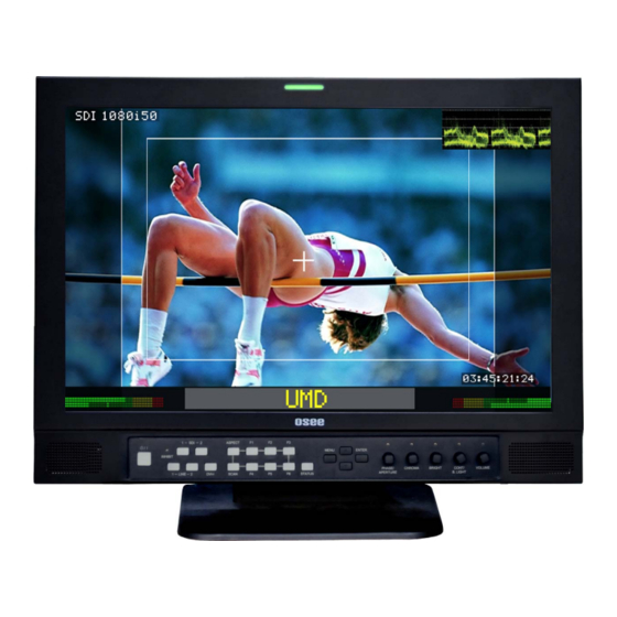
LMW-171 SERIES LCD MONITOR User Manual Chapter 4 Operation Status Display Wave form or vector graph TALLY Indicator Signal format Area & Safety Marker Audio Meter Speakers Time Code Tally Indicator: It is used to check the status of the monitor by the color of the tally lamp. (For more information, see the fourth page of “USER CONFIG”... -
Page 9: Input Signals
720P25 720P30 720P50 720P60 1035I60 1080I60 1080I50 1080P24 1080P25 1080P30 1080P50 1080P60 1080SF24 SVGA SXGA UXGA WVGA WXGA WUXGA *: For ”Device Type”, LMW-171 includes LMW-171V, LMW-171S and LMW-171H. “YES”: Adjustable/can be set; “\” : Not adjustable/cannot be set —5—... -
Page 10: Rear Panel Terminals
LMW-171 SERIES LCD MONITOR User Manual 4.3 Rear Panel Terminals A. Rear Panel The specifications of terminals are as follows : GPI :GPI Terminal Female RJ-45 Receptacle Description PIN 1 GPI1 PIN 2 GPI2 PIN 3 GPI3 PIN 4 GPI4 PIN 5 GPI5 PIN 6... - Page 11 LMW-171 SERIES LCD MONITOR User Manual 3 RS485 IN : RS485 IN Terminal ; 4 RS485 OUT : RS485 OUT Terminal ; Female RJ-45 Receptacles Pin No. RS485 IN Terminal Signal RS485 OUT Terminal Signal 5 Battery Mounter optional Install the Battery Mounter and Battery here. The Battery Mounter and Battery are accesories , if necessary, please contact the manufacturer.
- Page 12 LMW-171 SERIES LCD MONITOR User Manual B. Audio and video connectors —8—...
- Page 13 LMW-171 SERIES LCD MONITOR User Manual The specifications of terminals are as follows : SDI IN1 : SDI 1 Input Terminal SD-SDI input signal which is in compliance with SMPTE259M and ITU-R BT656 standard. SDI IN2 : SDI 2 Input Terminal SD-SDI input signal which is in compliance with SMPTE259M and ITU-R BT656 standard.
-
Page 14: Location And Function Of Control Buttons And Knobs On Front Panel
LMW-171 SERIES LCD MONITOR User Manual 4.4 Location and Function of Control Buttons And Knobs On Front Panel (1)POWER : Power Standby / ON Switch /– Press this switch to turn on the power of this unit or to set this unit in the standby mode(the power switch on the rear panel is turned on). - Page 15 LMW-171 SERIES LCD MONITOR User Manual (8)ASPECT Button/lamp Press to set the aspect ratio of the picture, 4:3 or 16:9. Scaled mode only effects for SD signal. For VGA, DVI and HD input signal, it is not valid and is defaulted to 16:9 mode.
- Page 16 LMW-171 SERIES LCD MONITOR User Manual (12)MENU, ENTER, UP, DOWN Button Displays or sets the main menu. Menu button: Press to display the main menu, when the on-screen menu is not the main menu. Press again to clear the main menu. (For more information, see the chapter 5) Enter button: Press to confirm a selected item on the menu, when the on-screen menu is the main menu .
-
Page 17: Input Signals And Adjustable/Setting Items
LMW-171 SERIES LCD MONITOR User Manual (16) CONT Knob Displays and adjusts the picture contrast value: 1. Press this knob to display the picture contrast value. 2. Adjust the knob clockwise, the value increases. Adjust the knob counter-clockwise, the value decreases. -
Page 18: Chapter 5 Menu Operation Guide
LMW-171 SERIES LCD MONITOR User Manual Chapter 5 Menu Operation Guide 5.1 Selecting the Menu Language You can select one of two languages (English, Chinese) for displaying the menu and other on-screen displays. ”English” is selected in the default setting. The current settings are displayed in place of the marks on the illustrations of the menu screen. -
Page 19: Using The Menu
LMW-171 SERIES LCD MONITOR User Manual 5.2 Using the Menu The unit is equipped with an on-screen menu for making various adjustments and settings such as STATUS, COLOR TEMP, MARKER, etc. The current settings are displayed in place of the marks on the illustrations of the menu screen. -
Page 20: Chapter 6 Lmw-171 Series Lcd Monitor Menu Structure
The STATUS menu is used to display the current status of the unit. The following items are displayed. For the video inputs include SDI1, SDI2, Line1, Line2 or DVI-I (HDMI input only), the following items are displayed. STATUS FORMAT SDI1 1080I50 COLOR TEMP COMPONENT LEVEL SMPTE NTSC SETUP SCAN MODE NORMAL AUTO STANDBY MODEL* LMW-171H —16—... - Page 21 15.63kHz 60Hz AUTO STANDBY MODEL* LMW171-H * For Model, it will display LMW-171H or LMW-171S or LMW-171V, depending on the unit model. COLOR TEMP The COLOR TEMP menu is used for adjusting the picture white balance. Sub Menu Settings Explanation...
- Page 22 LMW-171 SERIES LCD MONITOR User Manual MARKER The MARKER menu is used for setting the marker. Sub Menu Settings Explanation MARKER -MARKER ENABLE ON <ON> marker displayed <OFF> marker not displayed -AREA MARKER 15:9 Selects the area marker aspect ratio according to the display aspect, For display aspect ratio is 16:9 <OFF>...
- Page 23 LMW-171 SERIES LCD MONITOR User Manual Sub Menu Settings Explanation -MARKER LEVEL <1> Sets the luminance to display safety, center and area marker line. <1>: 50% white level <2>: 75% white level <3>: 100% white level -MARKER MAT <OFF> Sets the area marker mat transparency. <OFF>...
- Page 24 LMW-171 SERIES LCD MONITOR User Manual Sub Menu Settings Explanation VIDEO CONFIG PICTURE CONTROL -AUTO SETUP Automatic Pixel Adjustment, press to adjust the picture automatically to maximize clarity and correct H/V position for the VGA input signal -SHIFT H 50 Adjusts the horizontal position of the picture <0-100>...
- Page 25 LMW-171 SERIES LCD MONITOR User Manual Sub Menu Settings Explanation -SPEAKER R AUD 1R The same as above (EBD CH2) -METER POSITION HORIZONTAL <HORIZONTAL> <VERTICAL> -METER DISP OFF <OFF> <ON> -METER 1-4 DISP OFF <OFF> <1-2> <1-4> -METER 5-8 DISP OFF <OFF>...
- Page 26 LMW-171 SERIES LCD MONITOR User Manual Sub Menu Settings Explanation -METER 6 The same as above (EBD CH6) -METER 7 The same as above (EBD CH7) -METER 8 The same as above (EBD CH8) Press ∧(up)or ∨(down) button to select “NEXT PAGE” item, then press Enter button to display the next page menu as follows.
- Page 27 LMW-171 SERIES LCD MONITOR User Manual Sub Menu Settings Explanation USER CONFIG 1/5 SYSTEM SETUP -NEXT PAGE -BACKLIGHT 50 Adjusts the backlight <0 ... 100> -LINE 2 INPUT VIDOE Selects the LINE 2 input type <VIDEO> <Y/C> <YPbPr> -DVI-I INPUT VGA Selects the DVI-I input type <VGA>...
- Page 28 -NEXT PAGE OFF <ON> -UMD DISPLAY <OFF> RED <RED> -UMD COLOR <GREEN> <YELLOW> <WHITE> -UMD LMW-171H MONITOR 16 characters CHARACTER OFF <ON> -TC DISPLAY <OFF> Display --:--:--:-- if no TC in ANC OFF <OFF> -WAVE FORM <WAVE>:Waveform <VECT75> Vector graph <VECT100>...
- Page 29 LMW-171 SERIES LCD MONITOR User Manual Press ∧(up)or ∨(down) button to select “NEXT PAGE” item, then press Enter button to display the next page menu as follows. Sub Menu Settings Explanation USER CONFIG 3/5 FUNCTION BUTTON SETUP -NEXT PAGE -F1 BUTTON MARKER F1- F6 button functions can be set as follows: <MARKER>: Control all MARKER ON-OFF-ON...
- Page 30 LMW-171 SERIES LCD MONITOR User Manual Sub Menu Settings Explanation USER CONFIG 4/5 GPI SETUP -NEXT PAGE -GPI1 TALLY R <NONE> <TALLY R> <TALLY G> <SDI 1> <SDI 2> <LINE 1> <LINE 2> <DVI-I> <H/V DELAY> <MONO> <BLUE ONLY> <NORMAL SCAN> <OVER SCAN>...
- Page 31 LMW-171 SERIES LCD MONITOR User Manual Sub Menu Settings Explanation USER CONFIG 5/5 -NEXT PAGE -UMD PROTOCAL LOCAL LOCAL/TSL3.1/TSL4.0/IMAGE VIDEO LOCAL: Use UMD setting (USER CONFIG 2/5) to control the UMD. TSL3.1: Use the TSLV3.1 protocol setting to control the UMD from a TSL tally controller. TSL4.0: Use the TSLV4.0 protocol setting to control the UMD from a TSL tally controller.
- Page 32 LMW-171 SERIES LCD MONITOR User Manual state, and open circuit corresponds to a HIGH state. This mode requires to the UMD tally mode parameter to be set. IMAGE VIDEO 422: Use the setting to control tally state via 422 port. GPI toggle is no available.
-
Page 33: Chapter 7 Technical Specifications
LMW-171 SERIES LCD MONITOR User Manual Chapter 7 Technical Specifications 7.1 Product Detailed Information: 17” diagonal (14.68 8.25”, 372.918H 209.664V) Display Area 178 degree (H) 178 degree (V) Viewing Angles 16.7M Color Depth 1366H 768V Resolution 0.091 H 0.273 V Dot Pitch 900 :1 Contrast Ratio... -
Page 34: Standard Definition Video, Frame Refresh Rate And Color Matrix (1920×1200)
LMW-171 SERIES LCD MONITOR User Manual × 7.4 Standard Definition Video, Frame Refresh Rate and Color Matrix (1920 1200) Tab.1 OVERSCAN NATIVE INPUT OUTPUT INPUT OUTPUT 1366X768(16:9) NTSC 684X462 720X487 720X487 1024X768(4:3) 1366X768, 684X548 720X576 720X576 1024X768 1366X768, SECAM 684X548 720X576 720X576 1024X768... - Page 35 LMW-171 SERIES LCD MONITOR User Manual Tab.2 FULL NORMAL Frame Color Matrix Rate INPUT ALL OUTPUT NORMAL 1366X768(16:9) NTSC 720X487 1024X768(4:3) 1366X768, 720X576 1024X768 1366X768, SECAM 720X576 1024X768 1366X768, NTCS-4.43 720X487 1024X768 1366X768, PAL-M 720X487 1024X768 1366X768, 480I60 720X487 601/709 1024X768 1366X768, 576I50...
-
Page 36: Chapter 8 Supplied Accessories
LMW-171 SERIES LCD MONITOR User Manual Chapter 8 Supplied Accessories Standard accessories: 1. Display and Table Stand 2. AC Power Cord 3. Warranty Card 4. User Manual Optional accesories: Rackmount Ear:LMW171-A-RE Battery mounter:LMW171-A-BM Battery Handle (not conform to standard of ROHS) Note:Specifications are subject to change without notice.
Need help?
Do you have a question about the LMW-171H and is the answer not in the manual?
Questions and answers