Table of Contents
Advertisement
Quick Links
Advertisement
Table of Contents

Related Manuals for OSEE LCM215-HDR PLUS


Summary of Contents for OSEE LCM215-HDR PLUS
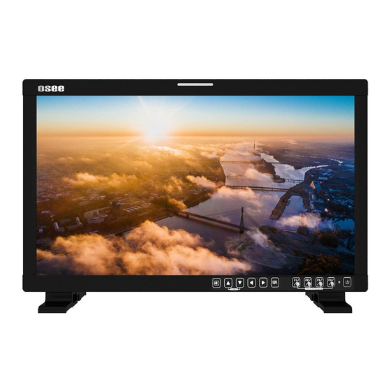
- Page 1 LCM215-HDR PLUS LCD Monitor User Manual...
- Page 3 Product Information Model: LCM215-HDR PLUS LCD Monitor Version: V010000 Release Date: January 24th, 2022 Company OSEE TECHNOLOGY LTD. Contact Information No.22 Building, No.68 zone, Beiqing Road, Haidian District, Address: Beijing, China 100094 Post Code: Tel: (+86) 010-62434168 Fax: (+86) 010-62434169 http://www.osee-dig.com/...
-
Page 4: Contents
The user manual applies to the following device types: LCM215-HDR+ LCM215-HDR Plus is called LCM215-HDR+ for short in the document below. The images of LCM215-HDR+ are adopted in the following descriptions. Before reading the manual, please confirm the device type. -
Page 5: Table Of Contents
Contents Contents ......................I Chapter 1 Overview ..................1 Chapter 2 Safety ..................... 3 Chapter 3 Unpack and Installation ............... 7 Chapter 4 Locations and Function of Parts and Control ......11 4.1 Front Panel ..................12 4.1.1 Arrangement of Front Panel ............12 4.1.2 Operation of Front Panel .............. -
Page 7: Chapter 1 Overview
Overview Chapter 1 Overview The LCM215-HDR+ LCD Monitor is a high performance field/studio monitor tailoring most applications from program production, intensive upload/download, playout to studio and intensive monitoring all sorts of business in TV Stations. The front frame of the unit comes in a slim bezel design made from rubber mold. - Page 8 Overview Features Prevailing slim bezel design Having multi-format input including 3G/HD/SD-SDI, VIDEO and HDMI Adopting full HD, wide viewing angle TFT glass Using 10-bit signal processing technology plus advanced conversion technology between the interlacing and the progressive ...
-
Page 9: Chapter 2 Safety
Safety Chapter 2 Safety FCC Caution Any Changes or modifications not expressly approved by the party responsible for compliance could void the user's authority to operate the equipment. This device complies with part 15 of the FCC Rules. Operation is subject to the following two conditions: (1) This device may not cause harmful interference, and (2) this device must accept any interference received, including interference that may cause undesired operation. - Page 10 Safety Warnings: Read, keep and follow all of these instructions for your safety. Heed all warnings. Device Install in accordance with the manufacturer's instructions. Do not beat with a hard object or scratch the LCD display. Do not make the freeze picture displaying on the screen time too long, otherwise, it will leave the afterimage on the screen.
- Page 11 Safety heat. A nameplate indicating operating voltage, etc., is located on the rear panel. The socket-outlet shall be installed near the equipment and shall be easily accessible. Power Supply Cord Do not defeat the safety purpose of the polarized or grounding-type plug.
-
Page 13: Chapter 3 Unpack And Installation
When unpacking the components of LCM215-HDR+ monitor, please verify that none of the components listed in Table 3.1 are damaged or lack. If there is any missing, contact your distributors or Osee Technology Ltd. for it. Table 3-1 Packing List... - Page 14 Unpack and Installation Figure 3-1 Stands Assembly Figure 3-2 Stands for LCM215-HDR+ Connect required cables for signal input and output. For BNC connections use 75Ω rated connectors. Connect 100~240V50/60Hz AC or 11~17V3A DC power source using the power cord, or 11~16.8V DC camera battery(with optional battery plate).
- Page 15 Unpack and Installation As a final step, turn on the device by pressing the corresponding power switch located on the front panel. The pedestal and the monitor are packaged separately. Connect a standard signal line to the corresponding input port. All BNC connector impedance must be 75Ω.
-
Page 17: Chapter 4 Locations And Function Of Parts And Control
Locations and Function of Parts and Control Chapter 4 Locations and Function of Parts and Control This chapter describes the features of LCM215-HDR+ monitor. The features of LCM215-HDR+ monitor are as shown in Figure 4-1 after installed and powered on: Figure 4-1 Features of LCM215-HDR+ Monitor Status Information The Status Information is displayed in the top left corner of the... -
Page 18: Front Panel
Locations and Function of Parts and Control display it or not and their displaying mode in USER CONFIG menu Center Marker It is displayed in the center of the screen, and marks the center of the image. You can set whether to display it or not in USER CONFIG menu. - Page 19 Locations and Function of Parts and Control Figure 4.1-1 the Buttons in Front Panel As shown in Figure 4.1-1, the buttons of LCM215-HDR+ are as follows: BUTTON FUNCTION BUTTON FUNCTION Function button F1/ User Input selection Preset button U1 Adjust upward/ Function button F2/ User Fast Menu Preset button U2...
-
Page 20: Operation Of Front Panel
Locations and Function of Parts and Control The power button has light indicators. 4.1.2 Operation of Front Panel The functionality and usage of the buttons at the front panel are as follows: : Input Selection Select the input signal from each input interface. Press this button to display the Input Source menu at the top right corner of the screen, as shown in Figure 4.1-2. - Page 21 Locations and Function of Parts and Control Adjust Menu Description Range Default Volume Adjust the volume 0~31 Brightness Adjust the image brightness 0~100 Contrast Adjust the image contrast 0~100 Saturation Adjust the image color intensity 0~100 Backlight Adjust the backlight 0~10 0 ~...
- Page 22 Locations and Function of Parts and Control : RIGHT ARROW Press this button to do the following operations: With the MAIN menu: Enter into the next level menu. Turn Page: when the current selection in the sub-menu list is Next Page, press this button to turn to the next page circularly.
-
Page 23: Rear Panel
Locations and Function of Parts and Control User Preset. If the value related to the function button can’t be modified, the value shows in gray. For F2/U2~F4/U4 function buttons, the operations are as the same as F1/U1's. Use FUNCTION KEY menu to assign F1~F4. You can assign the function from among: Camera LUT, Undef, Blue Only, Mono, Marker, Audio Meter, Time Code, Waveform Type, Vectorscope, Histogram, Scan, Aspect(Anamorphic), Native, Mute, IMD Display, False Color, Focus... -
Page 24: Operations Of Rear Panel
Locations and Function of Parts and Control Figure 4.2-1 Connectors in the Rear Panel The interfaces numbered in red are described as follows: Power Switch Video Input: VIDEO IN AC Power Input HDMI Input: HDMI IN DC Power Input Headphone Video Input: SDI1 IN Audio Input: AUD IN Video Input: SDI2 IN... - Page 25 Locations and Function of Parts and Control AC Power Input It provides one AC power input interface, the specification is 100~ 240V50/60HzAC. The power indicator is on the power button at the front panel. If the light is green, the monitor is powered on, and if the light is red, the monitor is standby.
-
Page 26: Supported Signal Format
Locations and Function of Parts and Control It provides two RS485 interfaces, loop out. Support for cascade connection and IMD remote control. The comparison of pins and Input connectors for RS485 is shown as in Table 4.2-1: Table 4.2-1 The Comparison of Pins and Input connectors for RS485 PIN No. - Page 27 Locations and Function of Parts and Control Signal HDMI VIDEO 1080I50 1080I60/59.94 1080P24/23.98 1080P25 1080P30/29.97 1080I50 4:2:2 YCbCr 12 BIT 4:4:4 YCbCr 10 BIT 1080I60/59.94 4:4:4 YCbCr 12 BIT ...
-
Page 29: Chapter 5 Menu Operations
Menu Operations Chapter 5 Menu Operations This chapter describes the structure and functionality of the Main menu, and introduces how to modify and customize the menu settings. The MAIN menu includes the following menu items, as shown in Figure5-1. Figure 5-1 MAIN Menu 5.1 MAIN Menu Press the OK/MENU button at the bottom of the front panel, the MAIN menu is displayed at the center of the screen, as shown in Figure 5.1-1:... - Page 30 Menu Operations The menu interface is divided into three parts: First level menu It contains the menu list of the MAIN menu. Press UP or DOWN to access the corresponding menu item. Second level menu Press right arrow button to enter into the second level of menu list, as shown in Figure 5.1-2, it lists the title, the sub-menu items and the value of the item.
-
Page 31: Status Menu
Menu Operations The following will introduce the contents and functionality of these sub-menu items in sorts. 5.1.1 STATUS Menu The STATUS menu items are used to describe the current status information of the monitor, the menu items are as shown in Figure 5.1-3: Figure 5.1-3 STATUS Menu There are two pages in STATUS menu. -
Page 32: Input Config Menu
Menu Operations Items Default Value Description Camera LUT Type Camera SDR Show the type of camera LUT User Preset USER1 Show the user preset name Page2 Model Show the production model. Serial Number Show the serial number. Firmware Version Show the firmware number. ... -
Page 33: Color Management Menu
Menu Operations Default Items Domain Range Description Value Page1 SDI IN1 ON/OFF Enable/Disable SDI1 input SDI IN2 ON/OFF Enable/Disable SDI2 input VIDEO ON/OFF Enable/Disable VIDEO input HDMI ON/OFF Enable/Disable HDMI input Set the NTSC phase level, and this item is available only NTSC Phase 0 -50~50 when NTSC format signal is... - Page 34 Menu Operations shown in Figure 5.1-5: Figure 5.1-5 COLOR MANAGEMENT Menu There are two pages in COLOR MANAGEMENT menu. The relationship of Items, Default Value, Domain Range and Description of the sub-item is shown in Table 5.1-4: Table 5.1-4 The Description of COLOR MANAGEMENT Menu Items Default Items Domain Range...
- Page 35 Menu Operations Default Items Domain Range Description Value ITU2020 Page2 Camera LUT ON ON/OFF Enable/disable camera LUT Camera SDR Camera LUT Camera from Camera HDR Type corresponding list User Camera SDR 2.2 Refer to Table 5.1-5 Load the selected SDR LUT Camera HDR --- Refer to Table 5.1-5...
- Page 36 Sony Sony_SLog3SG3Cine_LCRec709 Sony_SLog3SG3Cine_LCRec709A ARRI_LogC_HLG_Rec2020 ARRI_LogC_PQ_Rec2020 Canon_Clog2Cin_HLG_Rec2020 Canon_Clog2Cin_PQ_Rec2020 Canon_Clog3Cin_HLG_Rec2020 Canon_Clog3Cin_PQ_Rec2020 Panasonic_VLog_HLG_Rec2020 Osee Panasonic_VLog_PQ_Rec2020 RED_L3G10_HLG_Rec2020 RED_L3G10_PQ_Rec2020 Sony_SLog3_Cin_HLG_Rec2020 Sony_SLog3_Cin_PQ_Rec2020 Sony_SLog3_SG3_HLG_Rec2020 Sony_SLog3_SG3_PQ_Rec2020 When setting Camera LUT Type item as Camera SDR, Camera HDR or User, the following corresponding Camera SDR, Camera HDR, User item will be activated, and the available ranges of Gamma are...
- Page 37 Menu Operations diverse, as shown in the following table: Camera LUT Type Gamma Camera SDR 1.8/2.2/2.4/2.6/2.8/BT.1886 Camera HDR PQ/HLG User or OFF 1.8/2.2/2.4/2.6/2.8/BT.1886/PQ/HLG Load a user LUT from disk First, load a LUT file to the designated user LUT. Set COLOR Management...
-
Page 38: User Config Menu
Menu Operations TEMPRESET command to restore product originals for Gains, and press OK/MENU button to confirm the reset operation. 5.1.4 USER CONFIG Menu The USER CONFIG menu items are used to adjust the parameters defined by customers, the menu items are as shown in Figure 5.1-7: Figure 5.1-7 CONFIG Menu There are six pages in USER CONFIG menu. - Page 39 Menu Operations Default Items Domain Range Description Value Scan/ Aspect(Anamorphic)/ Native/Mute/IMD Display/ False Color/ Focus Assist/ Peak/Zebra Assign a function to F2 F2 Button Marker the same as F1 button Audio Assign a function to F3 F3 Button the same as F1 Meter button Assign a function to F4...
- Page 40 Menu Operations Default Items Domain Range Description Value and frame 0: 100% Set the transparency for Meter Opacity 1: 50% audio meter. Page 3 Set whether to show all of the markers. It is the Marker OFF/ON main switch for area marker, center marker and safety marker.
- Page 41 Menu Operations Default Items Domain Range Description Value 3: 100% safety marker, center marker, area marker and cross hatch. OFF: Normal background, use line for area marker Darkens the outside of edge only the area of the Aspect Marker Mat ...
- Page 42 Menu Operations Default Items Domain Range Description Value histogram display, and set the histogram mode Left Up Center Up Right Up Histogram Right Center Set the location of the Location RIGHT Right Down histogram Center Down ...
- Page 43 Menu Operations Default Items Domain Range Description Value sharpener the image. Enable/Disable false False Color OFF/ON color function Spectrum/SONY Slog3/ SONY Slog2/ARRI LogC/ Canon Clog2/ Canon Clog3/ Panasonic Vlog/ False Color RED RedLogFilm/ Set the type of the false Spectrum Type RED RL3G10/ color display...
- Page 44 Menu Operations Default Items Domain Range Description Value Set whether to restore Monitor Reset the factory settings Firmware Upgrade the firmware Upgrade 5.1.4.1 FUNCTION KEY and User Preset Menu User Preset The user preset provides a series of menu settings customized as a User Preset, up to 4 presets could be defined in this device.
- Page 45 Menu Operations Default Items Range Description Value display Scan Normal/Over Enable/Disable scan function As shown in 错误!未找 Aspect/ Set scaling ratio 到引用源。 Anamorphic Enable/Disable native Native OFF/Left/Center/Right function, and set its mode Mute OFF/ON Enable/Disable mute IMD Display OFF OFF/ON Enable/Disable IMD display Enable/Disable false...
- Page 46 Menu Operations Input Default Value Range Input Signal Formats Signal 2048X1080P24/23.98 2048X1080P60/59.94 2048X1080P25 Anamorphic This feature enables you to de-squeeze signals coming from camera utilizing anamorphic lenses that may not have a built-in de-squeeze feature of their own. This is quite useful in applications, such as outdoor post production, onset monitoring, real-time de-squeezing, etc.
- Page 47 LCM215-A and LCM215-HDR provide different scaling menus for various industry field. Aspect is for Radio and television industry, while Anamorphic is for film industry. Aspect and Anamorphic are alternative, and chose through the factory settings. Please contact your dealer or Osee Technical Support for the operation details. Mute Active this function to adjust the volume to 0, press the function button again to release the volume to the last value.
- Page 48 Menu Operations Figure 5.1-8 CONFIG Menu-Page2 The appearance of Meter is as shown in Figure 5.1-9: Figure 5.1-9 Audio Meter Audio Meter Display Mode Meter Select controls the amount of channels displayed in an audio meter, and each group(G*) contains four channels. As shown in Figure 5.1-10, the meter displays at the left bottom of the screen vertically.
- Page 49 Menu Operations Figure 5.1-10 The Position of the Audio Meter On Screen Audio Meter Display Position The position of Meter is controlled by Meter Position item, the position of the meter on the screen is as follows: Left, Right. For example, the illustrations of the positions are as shown in Figure 5.1-11: Figure 5.1-11 the Positions of Meter ...
- Page 50 Menu Operations Figure 5.1-12 USER CONFIG Menu-Page3 Markers Marker Illustration Description This marker enables easier checking the center portion’s focus. Center Marker This marker displays two lines to identify an area with a specified ratio. Aspect Marker This marker displays a rectangle to identify the safety area...
- Page 51 Menu Operations The marker mat marks the outside area of the marker display with the appointed transparency. For example, set ASPECT as 16:9, Aspect Marker as 4:3, and Area Marker as 95%, then, the comparison of the three Marker Mats are as shown in Figure 5.1-13: Figure 5.1-13 MARKER MAT MARKER FIT...
- Page 52 Menu Operations 5.1.4.4 Scope Menu The Scope menu items are displayed on Page4 in USER CONFIG menu, and they are used to adjust the parameters displayed on the screen, the menu items are as shown in Figure 5.1-15: Figure 5.1-15 USER CONFIG Menu-Page4 Display Location Set the location of waveform, vectorscope and histogram by USER CONFIG ...
- Page 53 Menu Operations Waveform Display Mode Set various waveform through USER CONFIG Waveform Type item, and display the following three kinds of waveform as LUMA, RGB, PARADE, shown in Figure 5.1-17: Figure 5.1-17 LUMA Waveform and RGB Waveform and PARADE Waveform ...
- Page 54 Menu Operations Histogram Histogram assists in judging the distribution of luminance in the image. Histogram Type Set USER CONFIG HISTOGRAM item to open or close the histogram display, and set the histogram display mode as LUMA or RGB, the two histogram types are as shown in Figure 5.1-19: Figure 5.1-19 RGB Histogram and LUMA Histogram 5.1.4.5 Focus and Exposure Menu...
- Page 55 Menu Operations Set USER CONFIG Focus Assist item to enable the focus assist function. The intensified edges are those areas whose difference value exceeds the reference focus level (SENSITIVITY), and the intensified edge are displayed in the designated color set by Focus Assist Color. ...
- Page 56 Menu Operations provides multiple types of FALSE COLOR types: Spectrum, SONY Slog3, SONY Slog2, ARRI LogC, Canon Clog2, Canon Clog3, Panasonic Vlog, RED RedLogFilm, RED RL3G10, BMD, BMD 4K, ARRI Rec709, SONY LC709A, SONY LC709, Panasonic V709, RED G3, RED G4. For example: Set USER CONFIG False Color item as ON and False Color Type item as ARRI LogC, as shown in Figure 5.1-23: Figure 5.1-23 Comparison Mode- Original Image and Normal Mode...
- Page 57 Menu Operations Figure 5.1-25 USER CONFIG Menu-Page7 Internal Signal Set USER CONFIG Internal Signal item as ON, it will display the color test pattern on the screen. Osd Time Set USER CONFIGOsd Time as 10s, 30s or 60s. After you have loaded the menu, it will be closed automatically if you do nothing operation within the OSD Time.
- Page 58 Menu Operations Set USER CONFIGStatus Display item as ON, the status menu will be displayed in the top left corner of the screen, and it includes the input channel and signal format. Language Set USER CONFIGLanguage item as Chinese or English, and the default menu language is English.
-
Page 59: Imd Config Menu
Menu Operations files from your USB drive and update your firmware. Make sure you have inserted your USB disk with the stored firmware files into the USB interface of the monitor, or it will inform you a “Can’t Detect USB” error. Figure 5.1-29 Warning for Firmware Upgrading ... - Page 60 Menu Operations Figure 5.1-30 IMD Menu The relationship of Items, Default Value, Domain Range and Description of the sub-item is shown in Table 5.1-10: Table 5.1-10 The Description of IMD Menu Items Items Default Value Domain Range Description Set whether to display IMD Display ON OFF/ON Characters...
-
Page 61: Key Inhibit Menu
Menu Operations When the IMD Protocol is set to be Local, it displays IMD characters set in IMD Char item, and the IMD Char could be composed of up to 16 characters or up to 12 Chinese characters. For other values of IMD Protocol, the IMD character abides by the corresponding protocol. -
Page 62: Menu Settings
Menu Operations 5.2 Menu Settings When checking or modifying the value of the menu item, cooperating with the following buttons: (LEFT), (DOWN), (UP), (RIGHT), OK/MENU. Operations to the MAIN menu Display the first level menu Press OK/MENU button to enter into the MAIN menu, it displays at the center of the screen. - Page 63 Menu Operations Turn Page Choose the Next Page selector, then press Right button or OK/MENU button to turn to the next page. Operations to second level menu item value Switch second level menu item value When the control icon is in second level menu item value, press DOWN or UP button to switch among its value list.
-
Page 65: Chapter 6 Specifications
Specifications Chapter 6 Specifications Product detailed information Specification Values LCM215-HDR + Model 21.5” Dimension Dimension(WxHxD) 517.0x319.0x 74.3mm Pixel Pitch (WxH) 0.24795×0.24795mm Aspect Ratio 16:9 Display Area (WxH) 476.064×267.786mm Viewing Angle (HxV) 178°x178° 1.06G Color Depth colors Resolution 1920×1080 Contrast (Typ.) 1000:1 Luminance (cd/㎡) 1500... - Page 66 Specifications Specification Values 3G-SDI /HD-SDI /SDI-SDI Input/Output Signal Type SMPTE 424M, SMPTE 292M, SMPTE 259M, SMPTE 297M Connector BNC per IEC 169-8 75Ω Impedance >18 dB 5 to 270 MHz Return Loss >15 dB 270 MHz to 1.5 GHz >10 dB up to 3 GHz Maximum Signal Level 800 mV pk-pk 10% Signal Amplitude...
- Page 67 Specifications Figure 6-2 Rear Panel(Unit: mm) Figure 6-3 Side View(Unit: mm)
- Page 68 Specifications Figure 6-4 Top View(Unit: mm) Specifications are subject to change without notice. ------------------No Text Below------------------...
- Page 69 FOR MORE INFORMATION PLEASE VISIT: http://www.osee-dig.com/ OSEE TECHNOLOGY LTD. No.22 Building, No.68 zone, Beiqing Road, Haidian District, Beijing, China Tel: (+86) 010-62434168, Fax: (+86) 010-62434169 E-mail: sales@osee-dig.com...
Need help?
Do you have a question about the LCM215-HDR PLUS and is the answer not in the manual?
Questions and answers