Table of Contents
Advertisement
Quick Links
Advertisement
Chapters
Table of Contents

Related Manuals for Orlanski ORLIGNO 100


Summary of Contents for Orlanski ORLIGNO 100
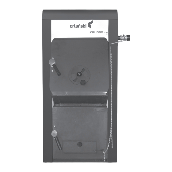
- Page 1 MANUAL AND SERVICE MANUAL ORLIGNO 100...
-
Page 2: Table Of Contents
Content 1. Boiler application ..............3 2. -
Page 3: Boiler Application
1. Boiler application Steel boiler ORLIGNO 100 tested according to EN 303-5 is designed for central heating installations with maximal temperature on the boiler 90ºC and working pressure 3 bar. Recommended fuel for boiler: wood, coke, coal and in case of mounting pellet burner – pellets and oats. -
Page 4: Installation
45°. Because of exhaust gases temperature ORLIGNO 100’s need to be connected to heat-resistant. 30 cm above the floor closing door should be installed with tight closing. -
Page 5: Technical Data
3. ORLIGNO 100 – technical data wood Power Coke/pellets 30/16 Boiler class acc. to EN-303-5 coke 76,5 Efficiency pellets Max working pressure Max temperature °C Min. temperature °C Water capacity ltr. Weight Loading chamber capacity ltr. Length 1100 Width Height... -
Page 6: Dimensions
3.1. Dimensions 3.2. Boiler construction... -
Page 7: Safety Valve Connection
3.3. Safety valve connection... - Page 8 ORLIGNO 100 is equipped with copper cooling coil mounted in boiler body, protecting boiler from overheating. To one of cooling coil tappings on right side of the boiler one should connect safety valve. When temperature increases above 95ºC safety valve opens and lets in cold water through cooling coil.
-
Page 9: Boiler Startup
4. Boiler startup Before first startup it is necessary to: - Check water level in installation, pressure in installation should be 2 bar. - Check fire-grate location (fire-grate gaps from bottom should be bigger than from top). - Draft regulator seal with oakum and mount, fit arm and block with screw. Startup: - Mount draft regulator horizontally, regulator set on 70°C. -
Page 10: Boiler Stoking
In order to avoid problem of tarring and condensation – keep high boiler temperatures, boiler must be properly sized to heated space to avoid oversizing – boiler then will work on low temperatures. 1. Boiler ORLIGNO 100 2. Pressure vessel 3. Radiator 4. -
Page 11: Maintenance
5. Maintenance Advice: Clean boiler works efficiently. Boiler life is extended. - Fire-grate and ash clean/remove daily. - Boiler must be cool during this activities. - Open upper door and remove cleaning flap. - Check if heat exchanger surfaces are cleaned, clean with brush. - Remove ash from bottom chamber ( ashpan may be hot). - Page 13 5.2. Burner’s assembly to ORLIGNO 100 ........
-
Page 14: Basic Informations
1. Basic informations 1.1. Construction description and burner application Self- cleaning burner is a new look into the automatic burning of solid fuels in Europe – pellets of 6-8 mm of diameter or as a option oats with maintaining low emissions, complying with European norms. -
Page 15: Fuel Characteristics
Useful functions of controller: You don’t have to keep in mind about next boiler service – it is shown on the display Statistics – function enables to preview - minimal, maximal and average burner’s power - fuel usage: minimal, maximal and average. Temperature’s parameters are shown as a digits and charts on big graphic display 1.2. -
Page 16: Transport And Delivery Specification
1.3. Transport and delivery specification Burner during transport should be secured with straps against leaning and movement. Burner need to be stored in roofed and dry place. Burner is delivered in separate boxes wrapped in foil. Boxes contains: pellet tank with lid, fuel feeder, burner with controller and elastic feeding pipe. -
Page 17: Burner's Technical Data
2. Burner’s technical data Parameter 16 kW Pellet power range 4 – 16 Oats power range* 3,6 – 14,4 Efficiency >94,5 CO emission <200 Weight Feeder length standard 1,3 – 1,6 Feeder length option 2.0;2.5;3.0 Fuel pelety Fuel diameter 6 – 8 Fuel (option) humidity<15% owies Voltage... -
Page 18: Package
1. Burner’s body 2. Grate 3. Fan 4. Feeder casing ( worm+ igniter) 5. Drive plate 6. Plate for electric connections 7. Sealant 8. Motoreducer 9. Burner’s casing Pic.2. Burner construction 3. Package Standard package: - burner - controller - fuel feeder - tank - manual - 4 refractory bricks... -
Page 19: Location And Package Installation
4. Location and package installation 4.1. Rules, norms, recommendations Boiler room should comply with construction law valid in country where boiler is installed. Pic.3. Package layout. -
Page 20: Boiler Room Recommendation
4.2. Boiler room recommendation - Package ( boiler, burner, tank, feeder) should be placed in separate room, centrally to heated rooms - Front door should open outside and must be made of nonflammable materials, with 0,8 width - Floor should be made of nonflammable materials or covered with 0,7 mm steel plate at minimum 0,5 m distance to door edges. - Page 21 Combustibility grade of building Building products products A – non-burning sandstone, concrete, bricks, fire plaster, Mortar, tile, granite B - hard burning cement board, fiberglass, mineral insulation C1- hard burning beech tree, oak tree, plywood C2 – middle burning pine, larch, spruce tree, cork, rubber floor cover C3 –...
-
Page 22: Putting Into Operation
7. Fit flexible pipe (8) on feeder’s pipe (6) and secure with band clip (9) 8. Fit flexible pipe (8) on burner’s pipe (10) and secure with band clip (9) 5.3. Adjustment of ORLIGNO 100 to work with pellet burner 1. Remove iron-cast grate from boiler. - Page 23 Pic.5. Burner assembly. Pic.6. Feeder assembly...
-
Page 24: Tank Assembly
5.4. Tank assembly... -
Page 25: Before Starting Of The Burner It Is Necessary
5.5. Before starting of the burner it is necessary: 1. Check installation condition. 2. Fill in pellet to the tank, cover with lid 3. Check if fuel contains any unwanted elements ( rocks, metal elements) 4. Screw in sensor’s sleeve in one of two probes on the right side of boiler behind safety coil 5. -
Page 26: Burner's Maintenance
6. Burner’s maintenance ATTENTION! It is necessary to put out, cool down and disconnect burner from power supply when servicing. Pay attention on hot burner’s surfaces – risk of burn. In order to keep high efficiency of burner it is recommended to clean and service it systematically. -
Page 27: Troubleshooting
7. Troubleshooting Type of defect Possible cause of defect Suggested repair One of controller’s Display malfunction Display repair button doesn’t work Automatic lightning Wrong connection of igniter or Check plug and wires connections of igniter and up Doesn’t work photo-cell photo-cell Clogged outlet hole of hot air Clean heater hole... -
Page 28: Instrukcja Regulatora
8. Main functions of the controller. 8.1. Front panel Graphic display (2.1.3) Buttons (2.1.2) Status diode (2.1.1) 8.2. Status diode Lightning description Meaning Green- continuous light Controller off Green – pulsate Controller on, burner off Orange – continuous light Controller on, burner on Orange –... -
Page 29: Graphic Display
8.3. Buttons Function Button Return in menu to previous level, cancellation of parameter’s change. After pressing button > 3 sec – change of controller’s status ON/OFF Return, Esc Menu moving, decrease parameter’s value On main display entering to simple menu Arrow down Shows navigational informations and description of parameters... -
Page 30: Service
9.2. Grate statuses Status Description Burner doesn’t work. Work approval off. Cleaning Burner cleaning with strong stream of air. Lightning up Fuel lightning up. Initial fuel feeding, Heater and fan are on. Kindling After flame detection, additional fuel feeding and fan power increase for better grate kindling. - Page 31 10.3. Shutdown of the controller OFF In order to turn the controller off (mode OFF) press for 3 sec Return, Esc” on main display, when it is in ON mode. ATTENTION! After controller shutdown depending on its previous status, burner may still work (extinguishing ), it’s not advisable to disrupt this process.
- Page 32 ATTENTION! Values of economic and comfort temperatures are set in SETTINGS menu and may differ for each of the heating circuits. In order to activate time program activate it in SETTINGS menu. 10.5. Service password Access to service parameters is protected with password. After writing correct password access is cleared.
-
Page 33: Simple Menu
11. Simple menu 11.1. Simple menu’s displays Display Description Shows current boiler temperature (large type) and programmed temperature (small type). After pressing “Enter” button: set desired boiler’s temperature Shows current h.d.w. temperature (large type) and programmed temperature (small type). After pressing “Enter”... - Page 34 Shows current room temperature in room no.1 (large type) and set value (small type). After pressing “Enter”, set desired room temperature Circuit heating program no. 1: a. time program – according to programmed time- intervals b. permanent – no matter of time-intervals comfort temperature is kept c.
-
Page 35: Main Menu
12. Main menu 13 Heating strona 36 14 H.d.w page 38 15 Water tank page 40 16 Boiler page 40 17 Settings page 41 18 Burner page 41 19 Alarms page 43... -
Page 36: Heating
13. Heating 13.1. Circuit selection Enables to choose number of heating system circuit. Selection of circuit: “arrow down/up”. 13.2. Status Enables to monitor status of central heating. Circuit number Name of circuit Measured temperature/ programmed in room Measured temperature/ programmed in radiators Outside measured temperature Valve work time (sec) Programmed temperature at source (°C) - Page 37 13.3. Settings Description of functions in submenu SETTINGS. Function Description Comfort temperature Programmed temperature in room during heating. Programs: a. time program – according to programmed time- intervals b. permanent – no matter of time-intervals comfort Program temperature is kept c.
-
Page 38: Hot Domestic Water
14. Hot domestic water 14.1. Circuit selection Enables to choose number for h.d.w. circuit. 14.2. Status Enables to monitor status of h.d.w. Circuit number Circuit name Measured temperature/ programmed for h.d.w. Source programmed temperature (°C) Pump work signalling... - Page 39 14.3. Settings Description of functions in submenu SETTINGS Function Description Comfort temperature Programmed temperature of h.d.w. during heating period Programs: a. time program – according to programmed time- intervals Program b. permanent – no matter of time-intervals comfort temperature is kept c.
-
Page 40: Water Tank
15. Water tank 15.1. Service ATTENTION! Service menu is only for qualifi ed staff. Any settings’ changes may lead to incorrect system operation. 16. Boiler 16.1. Status Boiler work statistics during last 24h. Chart shows boiler’s temperature and burner power. 16.2. -
Page 41: Settings
Description of functions in submenu SERVICE: Function Description Pumps MIN temp Temperature above which controller may turn on the pumps Boiler’s work mode: Work mode a. auto – temperature set automatically b. continuous – temperature is kept continuously Hysteresis Temperature’s value that needs to decrease to start the burner. - Page 42 18.2. Settings Description of functions in submenu SETTINGS. Function Description Feed the fuel Starts feeder regardless of other functions. Burner’s work Burner’s work approval. Type of fuel Determines type of burned fuel. 18.3. Service ATTENTION! Service menu is only for qualified staff. Any settings’ changes may lead to incorrect system operation.
-
Page 43: Alarms
19. Alarms Menu contains history of maximum 20 alarms, that occured during controller’s work. Meanings of code alarms is shown below: Alarm codes and their meaning. Code Short description Description Processor’s overheating Controller’s processor has been overheated. Improper controller placement may be one of the reasons. Lack of fl ame/fuel Controller detected lack of fl ame in burner. -
Page 44: Electric Installation
20. Electric installation 20.1. Overall requirements Before use of this controller; it is necessary to thoroughly read instruction manual. Person responsible for controller’s installation should have technical experience. Connections made of copper should be adjusted to operate at temperatures of 75°C. All electric connections should comply with electric scheme enclosed in this manual and national or local rules concerning electric installations ATTENTION! - Page 45 ATTENTION! Connection works should be made when controller is disconnected from power. Only authorized person is allowed to do electrical connections with necessary qualifications. BACK VIEW OF CONTROLLER FILTER Output description Description Foto Brightness sensor in burner Tkotła Boiler sensor Tpalnik Burner sensor Tc.w.u.
- Page 46 20.4. Technical data PARAMETER VALUE Power supply ~230V/50Hz ±10% Power consumpion <6VA Outputs capacity: Central heating pump 100W Hot domestic water pump 100W Igniter 400W 150W Burner's feeder 150W Pellet tank feeder 150W Measurement accuracy ±4ºC Sensors NTC 10kΩ =3877K±0,75% 25/85 VISHAY BCcomponents Outside temperature...
- Page 48 EKO-VIMAR ORLAŃSKI Sp. z o.o. 48-385 Otmuchów, ul. Nyska 17b POLSKA / woj. opolskie T +48 77 400 55 80-81, 400 55 91 F +48 77 439 05 03, 400 55 96 E biuro@orlanski.pl www.orlanski.pl...
Need help?
Do you have a question about the ORLIGNO 100 and is the answer not in the manual?
Questions and answers