Table of Contents
Advertisement
Advertisement
Chapters
Table of Contents

Related Manuals for Orlanski ORLIGNO 400


Summary of Contents for Orlanski ORLIGNO 400
- Page 1 INSTRUCTION MANUAL & SERVICE MANUAL ORLIGNO 400 ISO 14001 ISO 9001...
-
Page 2: Table Of Contents
4.1. ORLIGNO 400 16kW ........ -
Page 3: Delivery
This manual contains information that is protected under copyright law. 1. Delivery ORLIGNO 400 package is packed on one pallet wrapped up with foil. External elements of ORLIGNO 400 are packed in cardbox: - pellet tank with elastic pipe and clamps... -
Page 4: Boiler View After Assembly
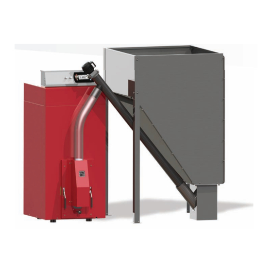
2. Boiler view after assembly 1. Boiler controller 2. Pellet tank 3. External auger 4. Feeding pipe 5. Burner 6. Lever for burner cleaning 7. Burner bin 8. Tube exchanger 9. Turbulators 10. Chimney fl ue... -
Page 5: Pellet Tank Assembly
3. Pellet tank assembly Bolt M8 A x 34 M5 x 8 Bolt B x 12 M5 x 16 C x 46 M5 D x 18 M8 E x 46 Bolt Washer Washer I x 1 M8 x100 F x 5 G x 1 H x 1 Plug... -
Page 6: Dimensions
4. Dimensions 4.1. ORLIGNO 400 16kW 4.2. ORLIGNO 400 30kW... -
Page 7: Technical Data
5. Technical data Type unit 16kW 30kW Weight 142,5 Flue Water outlet, return inch Efficiency 89,4 91,8 Power range 3,9-16 7,8-30 boiler class EN 303-5 Required draft min 10 min 10 Max working pressure Water content Max boiler temp. °C Min boiler temp. -
Page 8: Orligno 400 Package Assembly
6. Orligno 400 package assembly Mounting external equipment: 1. Attach burner plug to the burner socket (pic 1) 2. Assemble fuel tank acc. to enclosed manual. 3. Insert external feeder in to the tank: 4. Attach the elastic pipe between external feeder and the metal connector. -
Page 9: Cleaning Instructions
ATTENTION! It is recommended to use fuel from reliable sources. Fuel should have appropriate humidity and low content of small fractions. It is necessary pay attention especially to mechanical pollution ( stones), which worsen burning process and may lead to burner’s failure. Eko-Vimar Orlański sp. - Page 10 Maintenance – burner cleaning Remove the fi xing screw holding basket to the burner Take out the burner Remove burner’s basket Clean burner body and basket WARNING! Check permeability of basket holes. Maintenance – heat exchanger’s cleaning Unscrew upper cover Remove upper cover...
- Page 11 Unscrew upper exchanger cover Clean heat exchanger’s pipes and turbulators Pull out all turbulators...
- Page 12 WARNING! If boiler is not used for over 14 days it is necessary to empty pellet tank and feeding auger. Cleaning of pellet tank: Occasionally you have to empty the tank completely, in order to clean the area around the feeder inlet from pellet dust.
- Page 13 ASSEMBLY OF CLEANING MECHANISM - OPTION...
-
Page 14: Location And Package Installation
10. Location and package installation Recommended distances to the walls in the boiler room. min 100... -
Page 15: Boiler Room Recommendation
10.1. Boiler room recommendation - Package ( boiler, burner, tank, feeder) should be placed in separate room, centrally to heated rooms - Front door should open outside and must be made of nonflammable materials, with 0,8 width - Floor should be made of nonflammable materials or covered with 0,7 mm steel plate at minimum 0,5 m distance to door edges. -
Page 16: Safe Distance To Inflammable Substances
10.4. Safe distance to inflammable substances - During installation and exploitation it is advisable to maintain safe distance of 200 mm from inflammable substances - For inflammable substances with C3 grade of combustibility which rapidly and easy burn (ex. paper, cardboard, wood, plastic) distance is minimum 400 mm;... - Page 17 Controller's manual Contents 11. Connection - electric scheme ................19 12.
- Page 18 15.5. Settings ..................37 15.5.1 Date and time.
-
Page 19: Connection - Electric Scheme
11. Connection - electric scheme ORLIGNO 400 is equipped in boiler sensor. Boiler sensor is inserted into sleeve in boiler body together with STB thermal protection. Burner contains termic sensor glued to burner body as a burn-back protection. WARNING! External sensors for installation control such as hot domestic water HW1 or central heating CH1 are an option. - Page 20 INPUTS Description Explanation Tboiler Boiler temperature sensor Exhaust gas temperature sensor Tburner The temperature sensor burner The temperature sensor hot water Troom Room temperature sensor / regulator (CTP) The temperature sensor central heating Tout Outdoor temperature sensor (CTZ) +12V output to supply optional equipment +5V output to supply optional equipment Mass electric to connect sensors OUTPUTS...
-
Page 21: Overview Of The Basic Functions
12. Overview of the basic functions 12.1. Control panel 12.1.1 The status LED Status Importance Green light continuously Controller OFF Green blinks Controller enabled, burner OFF Orange light continuously Controller enabled, burner enabled Orange blinks Burner works Red light continuously There is an alarm to be confi rmed Red blinks Alarm active... -
Page 22: Buttons
12.1.2 Buttons Function Button Long press on the main screen (>3 seconds) changes the state of the ON/OFF (on/off). ON / OFF Quick access to the full confi guration settings for the central heating. Quick access to the full confi guration settings for hot water. Shows the navigation information and descriptions of the regulated parameters. -
Page 23: Graphic Display
12.1.3 Graphic display 12.2. Statuses of furnace Status Description TURNED OFF The burner is not working. Permission to work off . CLEANING Cleaning the burner by strong stream of air. FIRING UP Firing up fuel. Providing the initial dose of fuel to run igniter and blower. -
Page 24: Handling
13. Handling 13.1. Navigation in the menu The device has two types of menus: simple and main menus. Simple menu – allows for quick access to basic controller functions. Enter the menu is simple by pressing the “up arrow“ or “down arrow“ on the main screen. Description of a simple menu in chapter 11. -
Page 25: Time Scheduling
13.4. Time scheduling Controller is equipped with a clock and calendar. This makes it possible to program the operation of individual circuit elements for heating depending on the time and day of week. Date and time are not reset during a power failure, because the controller is equipped with a battery that should be replaced every two years. -
Page 26: Service Password
13.5. Service password Access to the service parameters are password protected. After entering the correct password, access will be lifted. Access to the service parameters will be locked after a period of 10 minutes without pushing buttons. Service code is a temperature of the boiler in menu BOILER / SETTINGS and 3 letters”EST”. Example: If the temperature of the boiler in menu BOILER / SETTINGS is 60°C, password is: „60EST”. -
Page 27: Simple Menu
14. Simple menu 14.1. Simple menu screens Screen Description Shows the current temperature of the boiler (large font) and the desired temperature (small font). After pressing the„ENTER” set the desired temperature of the boiler. Shows the current temperature of hot water (large font) and the desired temperature (small font). - Page 28 Shows the current temperature in the room No 1 (large font) and the value of the desired (small font). After pressing the „ENTER” go to set the desired temperature in the room. Menu relates to the circuit No. 1 Set the mode a heating circuit: a.
-
Page 29: Main Menu
15. Main menu... -
Page 30: Heating
15.1 Heating 15.1.1 Selection of circuit Allows you to select a number of central heating circuit. The selection of the circuit make arrows. 15.1.2 State Allows you to monitor the status of central heating system. -
Page 31: Settings
15.1.3 Settings Function Description Comfortable temp. Desired temperature in the room during the heating. Programs: a. time - according to preset intervals b. constant - regardless of the time intervals comfortable Programme temperature is maintained c. disabled - off the heat d. - Page 32 Function Description CH temp. for -20°C The point of the heating curve for -20°C. CH temp. for 0°C The point of the heating curve for 0°C. CH temp. for 10°C The point of the heating curve at 10°C. Service Central heating temperature correction required the desired room temperature for 1 º...
-
Page 33: Hot Water
15.2 Hot water 15.2.1 Selection of circuit Allows you to select the number of hot water circuit. 15.2.2 State Allows you to monitor the status of hot water. -
Page 34: Settings
15.2.3 Settings Function Description Comfortable temp. Desired temperature of hot water during heating. Set the mode a circuit: a. time - according to preset ranges Programme b. constant - regardless of the time intervals comfortable temperature is maintained c. disabled - off the heat. Heat now Heats hot water once to a comfortable temperature regardless of the program. -
Page 35: Buffer
15.3 Buff er (option available only with external module CAN) 15.3.1 State 15.3.2 Settings Function Description Upper set temperature Below this temperature in the upper part of the buff er starts charging. Lower set temperature Above this temperature at the bottom of a buff er comple- tes the process of charging. -
Page 36: Boiler
Function Description Minimal pump temp. The minimum temperature in the upper part of the buff er at which the circulating pump can work for central heating. Specifi es whether the upper temperature buff er (minimum) Auto upper temp. is requested manually or automatically. Automatically ba- sed on the needs of other power consumers in the buff er. -
Page 37: Settings
Function Description MIN pump temp. The temperature above which the the controller can attach pumps. Operating mode of boiler: Mode a. auto - temperature calculated automatically b. continuous - the temperature is kept constant Hysteresis The temperature of the boiler must be reduced by this value to launch the burner. - Page 38 15.5.4.1 Module configuration Menu is used to configure the CAN network. In the menu, select the modules that are connected to the system. WARNING! A detailed description of the modules and their destination are described in the manu- al of expansion modules. SUMMARY OF THE EXPANSION MODULES Module Description...
-
Page 39: Burner
15.5.4.2 System confi guration Menu is used to confi gure the heating system (hydraulic). The possibility of settings is dependent of number of expansion modules connected in the system. WARNING! You must fi rst confi gure the modules.. SYSTEM CONFIGURATION Function Description Number of CH circuits... -
Page 40: Settings
15.6.2. Settings Function Description Feed fuel now Starts fuel feeding screw regardless of other features. Burner on Consent to work of the burner. Fuel type Specifies the type of fuel. 15.6.3. Service WARNING! Access the service is intended only for qualified technical personnel. The changes may cause malfunction of the system. -
Page 41: Alarms
15.7 Alarms This menu contains a history of up to 20 alarms that occurred during the controller work. The importance of alarm codes was presented in table below. 15.7.1. Alarm codes CODE Short description Explanation Processor overheating Procesor overheating. The reason may be improper installation location of the controller. - Page 42 CODE Short description Explanation HW sensor open Room temp. sensor shorted Room temp. sensor shorted Quenching error Lambda communication Solars overheating Solars freezing The codes of the modules Shorted IN1 Module 0 Shorted IN2 Module 0 Shortede IN3 Module 0 Shorted IN4 Module 0 Shorted IN5 Module 0 Shorted IN6 Module0...
- Page 43 CODE Short description Explanation Shorted IN1 Module 1 Shorted IN2 Module1 Shorted IN3 Module 1 Shorted IN4 Module 1 Shorted IN5 Module 1 Shorted IN6 Module 1 Open IN1 Module1 Open IN2 Module 1 Open IN3 Module 1 Open IN4 Module 1 Open IN5 Module 1 Open IN6 Module 1 Overheating Module 1...
- Page 44 CODE Short description Explanation Open IN1 Module 2 Open IN2 Module 2 Open IN3 Module 2 Open IN4 Module 2 Open IN5 Module 2 Open IN6 Module 2 Overheating Module 2 Shorted IN1 Module 3 Shorted IN2 Module 3 Shorted IN3 Module 3 Shorted IN4 Module 3 Shorted IN5 Module 3 Shorted IN6 Module 3...
- Page 45 CODE Short description Explanation Open IN4 Module 3 Open IN5 Module 3 Open IN6 Module 3 Overheating Module 3 Shorted IN1 Module 4 Shorted IN2 Module 4 Shorted IN3 Module 4 Shorted IN4 Module 4 Shorted IN5 Module 4 Shorted IN6 Module 4 Open IN1 Module 4 Open IN2 Module 4 Open IN3 Module 4...
- Page 46 CODE Short description Explanation Overheating Module 4 Shorted IN1 Module 5 Shorted IN2 Module5 Shorted IN3 Module5 Shorted IN4 Module 5 Shorted IN6 Module 5 Shorted IN7 Module 5 Shorted IN8 Module 5 Shorted IN9 Module 5 Overheating Module 5...
-
Page 47: Solar
15.8 Solar (option available only with external module CAN) 15.8.1 State 15.8.2 Settings Function Description Turn on delta Temp. diff erence between solar and accumulator needed for solar pump turn on. Turn off delta Temp. diff erence between solar and accumulator needed for solar pump turn off . -
Page 48: Info
15.9 Info There you will fi nd useful information about the controller, including the version of software. 16. Expansion of the system - CAN bus The controller is equipped with a high bandwidth CAN bus used to communicate with the modules. - Page 49 Socket CAN bus is on the left side of the device. Connecting cable must be connected according to the following designation. Cable connection: L – line LOW (white) H – line HIGH (brown) GND – ground (grey) For connections on the CAN bus should be only used cable LiYCY 2x0,25. Only this type of cable gives the proper work of devices.
-
Page 51: Sonda Lambda
16.1 Sonda Lambda Lambda sensor we can connect to the system in two ways: – directly to the controller, if the entire system with CAN bus module will only use Lambda oxygen sensor, – through enlargement module I/O with the number 5, if in the system there are other modules enlargement. - Page 52 Find Lambda Module and turn it on by changing the option to YES At this point, turned on the module Lambda. The second step is a change the confi guration settings for the burner. From the main menu by selecting BURNER we get to the settings. Here you can again enter the mode SERVICE and if required, enter the access code.
-
Page 53: Solars
16.2 Solars Solar collectors are supported only by enlargement module I/O number 5th. After performing all the connections you must confi gure the controller to work with collectors proceed as described below. The fi rst step is to enable module number 5. From the main menu select SETTINGS Then in the mode SERVICE enter the access code After inputting the correct code, run the MODULES CONFIGURATION... - Page 54 Now enable the solar handling. As the main menu select SETTINGS and then enter the access code in the SERVICE mode After entering the code run SYSTEM CONFIGURATION Find the position Solars and activate them by changing the settings to YES After fi nishing confi guration the controller we can start to change the adjustment and settings for Solars.
-
Page 55: Specification
17. Specification Technical data Module supply voltage ~230V/50Hz ±10% Power input (module) <6VA Temperature measurement accuracy ±4ºC NTC 10kΩ B25/85=3877K±0,75% Sensors VISHAY BC components Ambient temperature 0-60 °C Moisture 5-95% non-condensing Software class Module output load capacity CH pump 100W HW pump 100W Igniter... - Page 56 EKO-VIMAR ORLAŃSKI Sp. z o.o. 48-385 Otmuchów, ul. Nyska 17b POLSKA / woj. opolskie T +48 77 400 55 80-81, 400 55 91 F +48 77 439 05 03, 400 55 96 E biuro@orlanski.pl www.orlanski.pl IO_ORLIGNO_400_07062013_EN...
Need help?
Do you have a question about the ORLIGNO 400 and is the answer not in the manual?
Questions and answers