
Related Manuals for aFe Power Quantum 2500


Summary of Contents for aFe Power Quantum 2500
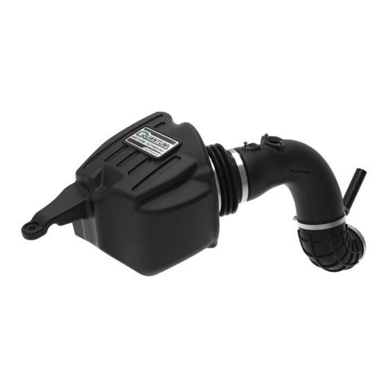
- Page 1 Cold Air Intake System Instruction Manual P/N: 53-10026D / 53-10026R ______________________________ Make: Dodge/RAM Model: 2500/3500 Year: 2007.5-2009 Engine: L6-6.7L (td) Cummins...
- Page 2 • Please read the entire instruction manual before proceeding. • Ensure all components listed are present. • If you are missing any of the components, call customer support at 951-493-7134. • Ensure you have all necessary tools before proceeding. • Do not attempt to work on your vehicle when the engine is hot. •...
- Page 3 A1/A2 Page 3...
- Page 4 REMOVAL Figure A Refer to Figure A for Steps 1-2 Step 1: Disconnect the wiring harness retaining clip 1 ,the MAF sensor 2 and the TBAP sensor 3 . Step 2: Using a 10mm socket and ratchet, remove the nut 4 holding down the factory housing. Page 4...
- Page 5 REMOVAL Figure B Refer to Figure B for Steps 3-4 Step 3: Using a pair of pliers, remove the crankcase breather hose and clamp 5 (factory clamp will be re- used). Step 4: Using an 8mm nut driver, loosen the clamp 6 connecting the factory intake tube to the turbocharger.
- Page 6 REMOVAL Figure C Refer to Figure C for Step 5 Step 5: Carefully lift up on the housing to release the two mounting pins from the mounting grommets 7 . Remove the entire intake from the vehicle. Page 6...
- Page 7 INSTALL Figure D Refer to Figure D for Steps 6-7 Step 6: Slide the aFe filter into the aFe housing. Install the aFe filter using a #3 Phillips screwdriver. Tighten all (x4) screws. Step 7: Install the supplied bellows coupling 8 onto the air filter using the supplied #80 clamp 9 . Tighten the clamp using an 8mm nut driver.
- Page 8 INSTALL Figure E Refer to Figure E for Steps 8-9 Step 8: Install the aFe housing assembly into the vehicle. Firmly push the housing into the factory mounting grommets. Step 9: Reinstall the factory nut 10 removed in Step 2 to secure the aFe housing. Tighten the screw using a 10mm socket and ratchet.
- Page 9 INSTALL Figure F Refer to Figure F for Steps 10-11 Step 10: Using a T20 Torx driver, remove the MAF sensor 11 and the TBAP sensor 12 from the factory housing. Step 11: Using a T20 Torx driver, transfer the sensors to the aFe intake tube using the supplied M4 screws. Page 9...
- Page 10 INSTALL Parting line on intake tube Figure G Refer to Figure G for Steps 12-14 Step 12: Install the supplied silicone hose 13 onto the aluminum fitting on the supplied elbow coupling 14 and secure with the supplied mini clamp 15 using a flat blade screwdriver. Slide the factory clamp 16 on the other end of the silicone hose.
- Page 11 INSTALL Figure H Refer to Figure H for Steps 15-17 Step 15: Place the other supplied #72 clamp 18 on the filter coupling 19 . Step 16: Place the #64 clamp 20 on the elbow coupling and install the aFe intake tube assembly onto the turbo first then slide it into the filter coupling.
- Page 12 Step 18: Reconnect the MAF sensor 23 and the TBAP sensor 24 plugs. Step 19: Check all the components are tight and secure. Your installation is now complete. Thank you for choosing aFe POWER! NOTE: Check all screws, clamps, and connectors are secure after 100-200 miles.
- Page 13 Page left blank intentionally Page 13...
- Page 14 Page left blank intentionally Page 14...
- Page 15 Page left blank intentionally Page 15...
- Page 16 252 Granite Street Corona, CA 92879 TEL: 951.493.7100 • TECH: 951.493.7134 E-Mail:Tech@aFepower.com...
Need help?
Do you have a question about the Quantum 2500 and is the answer not in the manual?
Questions and answers