Advertisement
Quick Links
Instruction Manual
Make: BMW
Model: 325i (E90/91)
Make: BMW
Model: 330i (E90/91/92/93)
Make: BMW
Model: 328i (E90/91/92/93)
Make: BMW
Model: 128i (E82/88)
P/N: 54-13053D / 54-13053R
Year: 2006
Year: 2006
Year: 2007-2013
Year: 2008-2013
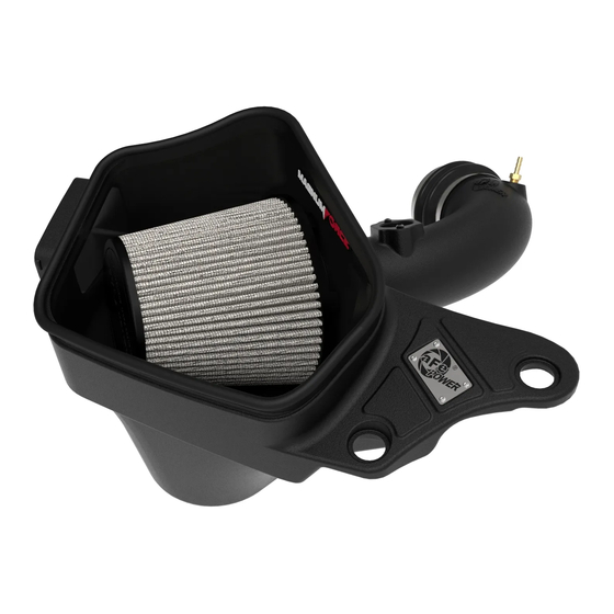
Magnum FORCE Stage-2 Cold Air Intake System
_____________________________
Engine: L6-3.0L Non-Turbo (N52)
Engine: L6-3.0L Non-Turbo (N52)
Engine: L6-3.0L Non-Turbo (N52)
Engine: L6-3.0L Non-Turbo (N52)
Advertisement

Related Manuals for aFe Power 54-13053D


Summary of Contents for aFe Power 54-13053D
- Page 1 Magnum FORCE Stage-2 Cold Air Intake System Instruction Manual P/N: 54-13053D / 54-13053R _____________________________ Make: BMW Model: 325i (E90/91) Year: 2006 Engine: L6-3.0L Non-Turbo (N52) Make: BMW Model: 330i (E90/91/92/93) Year: 2006 Engine: L6-3.0L Non-Turbo (N52) Make: BMW Model: 328i (E90/91/92/93) Year: 2007-2013 Engine: L6-3.0L Non-Turbo (N52)
- Page 2 • Please read the entire instruction manual before proceeding. • Ensure all components listed are present. • For technical support please call at 951-493-7185. • Ensure you have all necessary tools before proceeding. • Do not attempt to work on your vehicle when the engine is hot. •...
- Page 3 A1/A2 Page 3...
- Page 4 REMOVAL Figure A Refer to Figure A for Steps 1-5 Step 1: Remove the two (2) factory bolts and keep for later use 1 . Step 2: Disconnect the MAF sensor harness 2 . Step 3: Using a 6mm nut driver, loosen the hose clamp at the factory airbox 3 . Then, slide the factory intake tube away from the factory airbox.
- Page 5 REMOVAL FIGURE 1 Figure B Refer to Figure B for Steps 6-8 Step 6: For vehicles with the steering pump located above the factory intake tube, remove the two (2) factory nuts and keep for later use 5 . Step 7: Detach the factory air line from the reservoir’s bracket 6 . Step 8: Carefully move the steering pump reservoir to the front of the engine, to allow for clearance.
- Page 6 REMOVAL Figure C Refer to Figure C for Steps 9-11 Step 9: Using a 6mm nut driver, loosen the clamp at the throttle body 7 . Step 10: For vehicles with a crankcase breather (CCV) hose, detach the CCV hose from the factory intake tube 8 .
- Page 7 Step 13: For vehicles with a CCV hose, install the supplied NPT fitting into the aFe Power intake tube 10 . Step 14: For vehicles without a CCV hose, install the supplied NPT plug into the aFe Power intake tube 11 .
- Page 8 Refer to Figure E for Steps 15-17 Step 15: Remove the clamp from the supplied aFe POWER air filter’s flange. Slide the air filter into the aFe POWER housing from the top opening. Then, guide the air filter flange through the round opening in the housing and snap in the air filter.
- Page 9 INSTALL Figure F Refer to Figure F for Step 18 Step 18: Install the coupling onto the throttle body. Adjust the internal bead of the coupling into the groove of the throttle body. Once the coupling is fully seated and can rotate easily, tighten the clamp at the throttle body side (where there is an external bead to locate the clamp) 15 .
- Page 10 Step 19: Install the aFe Power intake tube into the coupling. Do not tighten the clamp at this time. Step 20: For vehicles with a CCV hose, connect the CCV hose to the aFe power intake tube 16 . Step 21: Connect the MAF harness to the MAF sensor 17 .
- Page 11 INSTALL Figure H Refer to Figure H for Steps 22-23 Step 22: Carefully, place the steering pump reservoir back on its bracket and tighten with the two (2) factory nuts from Step 6 18 . Step 23: Re-seat the factory air line from Step 7 back on the reservoir’s bracket 19 . Page 11...
- Page 12 Step 26: Insert the aFe Power housing into the factory air duct 20 . Step 27: Install the two (2) factory bolts from Step 1, and tighten down the aFe Power housing 21 . Step 28: Tighten the remaining clamps joining the aFe Power tube to the aFe Power air filter and coupling.
- Page 13 Page left blank intentionally. Page 13...
- Page 14 Pro DRY S Air Filter Pro 5R Air Filter Pre-Filter Pro DRY S Restore Kit P/N: 21-90113 P/N: 24-90113 P/N: 28-10153 P/N: 90-59999 Pro DRY S Restore Kit SPRINT BOOSTER V3 Cat-Back Exhaust Race Pipes P/N: 49-36319 P/N: 77-16302 P/N: 90-50501 P/N: 49-36313 Twisted Steel Headers Throttle Body Spacer...
-
Page 15: Warranty
Warranty General Terms: • aFe warrants their products to be free from manufacturer’s defects due to workmanship and material. • This warranty applies only to the original purchaser of the product and is non-transferrable. • Proof of purchase of the aFe product is required for all warranty claims. •... - Page 16 252 Granite Street Corona, CA 92879 TEL: 951.493.7100 • TECH: 951.493.7185 E-Mail:Tech@aFepower.com P/N: 06-81338...
Need help?
Do you have a question about the 54-13053D and is the answer not in the manual?
Questions and answers