
Related Manuals for RADEMACHER DuoFern 9482


Summary of Contents for RADEMACHER DuoFern 9482
- Page 1 DuoFern 1-10V Controller 9482 Instruction manual for the electrical connection and for commissioning Item no. 3500 12 62 Type: 9482 VBD 624-2 (01.21)
-
Page 2: Table Of Contents
Contents This manual.................4 How to use this manual ..............4 Hazard symbols ..............5 Levels of danger and signal words ..........5 Symbols and depictions used ............6 Safety instructions .............7 Intended use ..................7 Improper use ..................8 Expert knowledge required by the installer .......9 Glossary - definition ................9 Included in delivery ............ - Page 3 Contents 10. Manual mode ..............31 10.1 Operation with an external button ..........32 10.2 Jog mode ....................32 11. Deleting all settings (reset) ........... 33 12. Dismantling ..............33 13. Simplified EU declaration of conformity ..... 34 14. Warranty terms and conditions ........34...
-
Page 4: This Manual
1. This manual..describes how to install, connect and commission the DuoFern 1-10V Controller 9482. 1.1 How to use this manual ◆ Before you begin, please read this manual through completely and follow all the safety instructions. ◆ Please also read the instruction manuals of the accessories, if available, as well as the instructions of the respective con- nected appliance. -
Page 5: Hazard Symbols
2. Hazard symbols The following hazard symbols are used in this manual: Danger to life resulting from electric shock Danger area / dangerous situation 2.1 Levels of danger and signal words DANGER! This hazard will lead to serious injury or death if not avoided. WARNING! WARNING! This hazard may result in serious injury or death if not avoided. -
Page 6: Symbols And Depictions Used
2.2 Symbols and depictions used Depiction Description Procedures Itemisation ◆ 1) or a) Lists Further useful information Please read the respective manual... -
Page 7: Safety Instructions
3. Safety instructions The use of defective devices can lead to personal injury and damage to property (electric shock / short circuit). ◆ Never use defective or damaged devices. ◆ Check the DuoFern 1-10V Controller for damage. ◆ Consult our customer service department in the event that you discover damage, see page 36. -
Page 8: Improper Use
3.1 Intended use ◆ The installation and operation of the radio systems is only permitted for systems and devices where a malfunction in the transmitter or receiver would not cause a danger to persons or property or where this risk is already covered by other safety equipment. -
Page 9: Expert Knowledge Required By The Installer
DuoFern manual central operating unit. HomePilot® ◆ The HomePilot® is a central controller unit for RADEMACHER radio products. Electronic ballast ◆ An electronic ballast, for example to control LEDs and fluo- rescent lamps. -
Page 10: Included In Delivery
4. Included in delivery Included in delivery a) 1 x DuoFern 1-10V Controller 9482 incl. antenna b) 1 x instruction manual (not illustrated) -
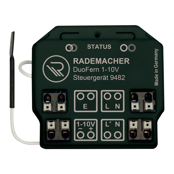
Page 11: Overview And Connections
5. Overview and connections Pos. Symbol Description External input 230 V / 50 Hz Connection of an external switch / button for manual control on site. 1 - 10V interface Connection of the 1-10V interface of an active electronic ballast. Power supply for electronic ballasts Output for the 230 V electronic ballast power supply. -
Page 12: Operating Buttons And Indicator Light
5.1 Operating buttons and indicator light Pos. Symbol Description Connect button Logging on to the DuoFern radio network or a DuoFern transmitter. STATUS Indicator light - status display green flashing Connection is active constantly Connection or disconnection lit up was successful brief Control command received flashing... -
Page 13: Functional Description
6. Functional description Lighting control With the DuoFern 1-10V Controller, you can connect electronic ballasts with a 1-10V interface and use them, for example, for dimming and controlling LEDs, LED strips or fluorescent lamps. An integrated relay switches the ballast on or off (approx. -
Page 14: Description Of The 1-10V Interface
1 V to 10 V. Ballasts / power supplies and the DuoFern 1-10V Controller are interconnected via a polarised, two-core control cable. The connection principle 230 V / 50 Hz supply voltage STATUS RADEMACHER DuoFern 1-10V DuoFern 1-10V Steuergerät 9482 Controller 9482 ´... - Page 15 6.1 Description of the 1-10V interface Characteristics of the 1-10V interface ◆ The voltage on the control lead is isolated from the mains lead. ◆ The voltage on the control lead is a safety extra-low voltage (SELV). ◆ The control voltage is generated by the electronic ballast. The DuoFern 1-10V Controller serves as an adjustable resistor (sink).
-
Page 16: Functional Characteristics
/ off ● ● ● ● on / off 10. Sun function ● ● 11. Automatic sun function on / off on / off ● ● ● ● The "WR ConfigTool" software can be downloaded from our website at www.rademacher.de. - Page 17 ● 22. Stairway time (pulse duration) *** 100 ms - 3276 s 3 minutes ● ● The "WR ConfigTool" software can be downloaded from our website at www.rademacher.de. *** Advanced switch-off warning for > 60 seconds and with uneven values.
-
Page 18: Description Of The Functions And Parameters
6.3 Description of the functions and parameters Setting the dimming speed This sets the time which the 1-10V output requires to get from 0 % to 100 %. The possible adjustment range is 2 to 255 seconds. If the "Save intermediate value for a manual stop" function is activated, the dimming speed should not be set too fast for convenient use. - Page 19 6.3 Description of the functions and parameters Setting the intermediate value (1- 99%) There are two ways to set the intermediate value. ◆ If the “Save intermediate value for a manual stop” function is activated (factory setting), the current value configured by a stop command during dimming is saved as a new interme- diate value.
- Page 20 6.3 Description of the functions and parameters Light/device mode By switching between the light and device mode, the behaviour of the DuoFern 1-10V Controller can be changed: The range of functions changes as follows: Switching commands of an Device Light external DuoFern transmitter mode mode...
-
Page 21: Technical Specifications
7. Technical specifications Mains connection [ L / N ] Mains supply 230 V / 50 Hz voltage: Consumption: Standby: < 0.5 W External input [ E ] for a manual switch / button on site Input voltage: 230 V (Ri = 200 kW) Potential-free input 1 - 10V interface [ –... - Page 22 7. Technical specifications 230 V / 50 Hz Output / load contact [ L‘ ] Supply voltage: 230 V / 50 Hz Maximum switching Ohmic load, e.g. bulbs capacity: 6.5 A / 1500 W Fluorescent lamps 5 A / 1150 W Extra-low voltage bulbs, e.g.
- Page 23 7. Technical specifications DuoFern radio technology Transmission frequency: 434.5 MHz Transmission power: Max. 10 mW Range: Indoors: approx. 30 m * Outdoors: approx. 100 m * Depending on the building structure Max. number of DuoFern devices: General information Fuse rating: External 16 A (with medium time lag or with time lag) Permissible ambient...
-
Page 24: Connecting The Duofern 1-10V Controller
8. Connecting the DuoFern 1-10V Controller Prior to the electrical connection, check that the voltage / frequen- cy on the type plate corresponds to that of the local mains supply. 8.1 Safety instructions for the electrical connection DANGER! There is a risk of fatal electric shock when touching electri- cal components. - Page 25 8.1 Safety instructions for the electrical connection WARNING! WARNING! There is a risk of fatal injury caused by short circuiting when the DuoFern 1-10V Controller is overloaded. ◆ The maximum load of the 1-10V interface is 60 mA. ◆ Please refer to the respective operating manual for the ballast load.
-
Page 26: Important Information Regarding The Electrical Connection
8.2 Important information regarding the electrical connection Connection instructions for operating with an external switch / button on site ◆ The voltage applied to the external input [ E ] is internally decoupled and may also come from a phase other than [ L ] if required. -
Page 27: Connecting And Installing The Duofern 1-10V Controller
8.3 Connecting and installing the DuoFern 1-10V Controller Ensure the mains are current-free and check whether the inlet leads are current-free. Securely lay the connecting cables in the flush-mounted box of the DuoFern 1-10V Controller. Remove the insulation on all leads as specified above and con- nect them according to the following connection diagram. -
Page 28: Connection Diagram
8.4 Connection diagram 230 V / 50 Hz 230 V / 50 Hz STATUS RADEMACHER DuoFern 1-10V Steuergerät 9482 External ´ 1-10V button 1-10 V control Connected to lead 230 V / 50 Hz Active elec- Fluorescent tronic ballast 1-10 V... -
Page 29: Logging Duofern Transmitters On / Off
9. Logging DuoFern transmitters on / off You must assign every required DuoFern transmitter to the DuoFern 1-10V Controller in order that the DuoFern 1-10V Controller can be operated with a DuoFern transmitter. You can log on a maximum of 20 DuoFern transmitters (e.g. DuoFern manual transmitter standard). -
Page 30: Logging On And Off Via Radio Code
9.1 Logging on and off via radio code You can control the DuoFern 1-10V Controller directly using the ra- dio code in order, for example, to be able to connect other DuoFern transmitters to the DuoFern 1-10V Controller after installation. You will find the radio code on the enclosed label and on the rear side of the DuoFern 1-10V Controller. -
Page 31: Manual Mode
10. Manual mode Overview of the switching commands and actions 100 % Switching command Device Light mode mode UP # 100 % STOP DOWN # 100 % 100 % Dawn function 100 % Automatic dusk function Sun programme STOP * 100 % UP with current dimming direction 100 % STOP *... -
Page 32: Operation With An External Button
10. Manual mode Key to the previous table If the last intermediate state has been reached, then the DuoFern 1-10V Controller stops here. No intermediate state is saved upon connecting the mains power supply. The current brightness of the lamp is saved as the intermediate state. More information about the functionality ◆... -
Page 33: Deleting All Settings (Reset)
11. Deleting all settings (reset) A reset must be carried out to reset the DuoFern 1-10V Controller to the default factory settings. Press and hold the disconnect button for approx. 5 seconds until the STATUS LED constantly lights up red. All of the settings are deleted and reset to the default factory settings and the logged-on DuoFern transmitters are automati- cally logged off. -
Page 34: Simplified Eu Declaration Of Conformity
14. Warranty terms and conditions RADEMACHER Geräte-Elektronik GmbH provides a 24-month war- ranty for new systems that have been installed in compliance with the installation instructions. All construction faults, material de- fects and manufacturing defects shall be covered by the warranty. - Page 35 Proof of this must be provided by presenting a copy of the invoice. RADEMACHER will remedy any defects that occur within the war- ranty period free of charge either by repair or by replacement of the affected parts or by supplying a new replacement unit or one to the same value.
- Page 36 RADEMACHER Geräte-Elektronik GmbH online shop Buschkamp 7 46414 Rhede (Germany) info@rademacher.de www.rademacher.de Service: * 30 seconds free of charge, subsequently Hotline 01807 933-171* 14 cents / minute from German fixed line Fax +49 2872 933-253 networks and max. 42 cents / minute from service@rademacher.de...
Need help?
Do you have a question about the DuoFern 9482 and is the answer not in the manual?
Questions and answers