RADEMACHER Troll Comfort Instruction Manual For The Electrical Connection And For Commissioning
Source: rademacher.de
Table of Contents
Advertisement
Quick Links
Advertisement
Chapters
Table of Contents

Related Manuals for RADEMACHER Troll Comfort


Summary of Contents for RADEMACHER Troll Comfort
- Page 1 Troll Comfort / Troll Comfort 3D Instruction manual for the electrical connection and for commissioning Item no. Troll Comfort / Troll Comfort 3D 3650 00 12 / 3650 07 12 (ultra-white) 3650 05 22 / 3650 07 22 (aluminium) Type: 5625-UW, 5625-AL / 5635-UW, 5635-AL VBD 594-2 (01.21)
-
Page 2: Table Of Contents
Important information prior to the electrical connection and installation ............30 Electrical connection ................ 32 Connecting a tubular motor to the Troll Comfort ....33 Connecting a lamp to the Troll Comfort * ........ 34 Connecting a tubular motor to the Troll Comfort 3D... 35 Installation after the electrical connection ...... - Page 3 Contents 11. Introduction to opening the menus and setting the functions ............38 12. Initial commissioning with the help of the installation wizard ..............40 13. Manual operation ..............43 14. Moving to a target position ..........44 15. Menu overview ..............45 16.
- Page 4 Contents 25. Menu 9 - System settings ............ 76 25.1 Menu 9.1 - Setting the time and date ........77 25.2 Menu 9.2 - Configuring the motor run time ......78 25.3 Menu 9.3 - Configuring the ventilation position ....80 25.4 Menu 9.4 - Setting the postcode ..........
-
Page 5: This Manual
◆ This manual is part of the product. Please store it in an easily accessi- ble place. ◆ When passing the Troll Comfort or Troll Comfort 3D on to a third party, this manual must be passed on as well. -
Page 6: Hazard Symbols
2. Hazard symbols The following hazard symbols are used in this manual: Danger to life resulting from electric shock Danger area / dangerous situation 2.1 Levels of danger and signal words DANGER! This hazard will lead to serious injury or death if not avoided. WARNING! WARNING! This hazard may result in serious injury or death if not avoided. -
Page 7: Symbols And Depictions Used
2.2 Symbols and depictions used Other useful information Please read the respective manual Procedures ◆ Itemisation or a) Lists Activated menu symbols and setting parameters flash on the display. Information about opening the menus and setting the parameters can be found on page 38. -
Page 8: Safety Instructions
◆ Please contact our Customer Service if you find any damage, see page 112. Improper use leads to an increased risk of injury. ◆ Train all personnel to use the Troll Comfort or Troll Comfort 3D safely. ◆ Children must not play with the device. -
Page 9: Intended Use
◆ The tubular motor must be fitted with a mechanical or electronic end position switch. ◆ Only operate the Troll Comfort or Troll Comfort 3D in dry rooms ◆ A 230 V/50 Hz power supply, together with a site-provided discon- necting device (fuse), must be available at the installation location. -
Page 10: Improper Use
Troll Comfort or Troll Comfort 3D is used outside or in damp rooms. Do not install and use the Troll Comfort or Troll Comfort 3D outside or in damp rooms. 3.3 Expert knowledge required by the installer... -
Page 11: Glossary - Definition
3.4 Glossary - definition ◆ UW = ultra-white (device colour) DIN 49075 ◆ German Standard "Cover panels for installation devices for building into device boxes..." ◆ Extra low voltage... -
Page 12: Included In Delivery
4. Included in delivery Included in delivery 1 x Operating unit (50 x 50 mm) 1 x Frame 1 x Installation housing 1 x Spacer frame, see page 36 1 x Instruction manual (not illustrated) After unpacking please check and compare.. -
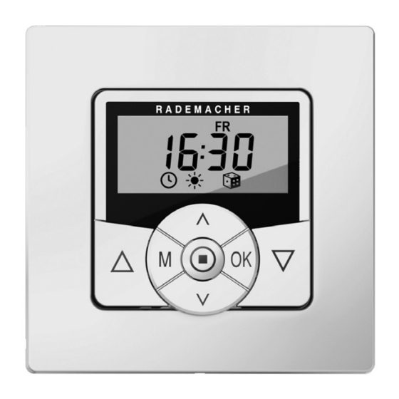
Page 13: General View Of The Operating Unit
5. General view of the operating unit Pos. Symbol Description Operating unit Display Menu button ◆ Open the main menu ◆ Back to the previous menu or standard display Setting buttons ◆ Select a menu in the main menu ◆ Set the parameters (more / less) Short press or press and hold = gradual or ●... - Page 14 5. General view of the operating unit Pos. Symbol Description OK button ◆ Open the selected menu ◆ Confirm and save settings ◆ Continue to the next setting Operating buttons Up / Down ◆ Manual operation SET/Stop button ◆ Manual stop of the roller shutter travel ◆...
-
Page 15: General View Of The Installation Housing
5.1 General view of the installation housing Pos. Symbol Description Installation housing Claw fasteners and screws Connecting terminals Type plate (example for the Troll Comfort) -
Page 16: Electrical Connections
Troll Comfort Power supply - 230 V / 50 Hz, 60 Hz E1 / E2 Troll Comfort - external inputs - optional Connect external signal transmitters, e.g. Venetian blind switches/external sensors etc., see page 33 / Both inputs are independently configured, see page Rotation direction (up / down) Connecting cables to the tubular motor. -
Page 17: Display And Its Symbols
5.3 Display and its symbols Symbol Description Weekdays (Monday ... Sunday) MO ... SO Time / setting parameters Information Switching time programme Offset (for astro time) OFFSET Setting Automatic mode AUTO Postcode Actual value Direction of travel (up/down) Automatic mode off Switching times Automatic dusk function... -
Page 18: Automatic Sun Function
Automatic rain function * System settings Set value SOLL Automatic slat adjustment Jog mode Light function * NORMAL Switching modes (NORMAL / ASTRO / SENSOR) Blockage detection * Position (in percent) Automatic button lock * not available for the Troll Comfort 3D... -
Page 19: Product Description
◆ with an external controller via the two inputs E1 and E2 The Troll Comfort has two configurable inputs E1 and E2 (230 V / 50 Hz) for connecting external signal transducers (e.g. Venetian blind switches / external sensors etc.), see page 33 / 34. -
Page 20: Description Of The Safety Functions
6.1 Description of the safety functions Troll Comfort with blockage detection * The Troll Comfort is able to monitor the torque of motors equipped with a mechanical end point setting. This enables the controller to switch off the motor in the event of overloading or blockage, see page 85. -
Page 21: Overview Of Functions
6.2 Overview of functions ◆ Display background lighting ◆ Installation wizard for easy commissioning ◆ Configurable blockage detection for mechanical tubular motors ◆ Manual operation on site ◆ Direct configuration and movement to a target position ◆ Switch automatic mode on/off ◆... -
Page 22: Venetian Blind Mode
◆ External control via the two configurable inputs E1 / E2 * ◆ Delete or reset all data * not available for the Troll Comfort 3D Description and configuration of the individual functions A precise description of the individual functions and settings is included... -
Page 23: Technical Specifications
230 V / 50 Hz 8 (4) A µ (Type 1B) Switching capacity: Personal injury and property damage may occur if the Troll Comfort is used to disconnect the connected appliance. ◆ Small contact distance (µ), not suitable for disconnecting the device. - Page 24 Switching voltage: 230 V / 50 Hz 8 (4) A µ (Type 1B) Switching capacity: Troll Comfort / Troll Comfort 3D General information External dimensions (W x H x D) 50 x 50 x 12 mm Operating unit [ 1 ]:...
-
Page 25: Factory Settings
2 30 - Reversing function: Jog mode: Automatic slat adjustment: Tilting time / slat runtime: 1.5 seconds (1500 ms) 100 - 5000 ms (0.1 to 5 sec.) Automatic summer / winter change- over: * not available for the Troll Comfort 3D... - Page 26 7.1 Factory settings Factory settings Display contrast: Display backlighting: Timer mode: * 1 (50 Hz) Button lock: Inputs E1 / E2: * OFF / OFF Reversal of direction of rotation: Light function: * * not available for the Troll Comfort 3D...
-
Page 27: Conduct In The Event Of A Power Failure
Power reserve (approx. 8 hours) The current time flashes for approx. 5 minutes in the event of a power failure and the Troll Comfort or Troll Comfort 3D changes to power reserve. Time and date after a power failure The power reserve is approx. 8 hours. If this time is exceeded, the time and date are lost and need to be reset, see page 77. -
Page 28: Safety Instructions For The Electrical Connection
◆ Check that the system is de-energised. WARNING! WARNING! Overloading of the Troll Comfort can lead to personal injury and destruction of the device (short circuiting). The maximum switching capacity must not be exceeded; please ob- serve the details in the technical specifications, see page 23. - Page 29 (electric shocks / short circuiting). ◆ Only use the installation housing provided to connect and install the Troll Comfort or Troll Comfort 3D. ◆ Installation housings of other RADEMACHER products, such as other Troll controllers, are not compatible. WARNING!
-
Page 30: Important Information Prior To The Electrical Connection And Installation
Parallel connection of electronic tubular motors A maximum of 3 tubular motors can be connected in parallel to the Troll Comfort or Troll Comfort 3D (e.g. RADEMACHER electronic tubular motors). In order to do so, follow the information in the instruction manual of the tubular motor being used. - Page 31 The maximum cable length for connecting external signal transducers to E1 or E2 must be 15 metres. Installation materials The Troll Comfort and Troll Comfort 3D are designed for flush-mounted installation. We recommend installation in a deep 58 mm flush-mount- ed box or in an electronic socket.
-
Page 32: Electrical Connection
Remove the insulation on all wires down to 6 mm in length and connect them according to the connection diagram on the following pages. After the electrical connection, the installation of the Troll Comfort or Troll Comfort 3D into the flush-mounted box is carried out, see page 36. -
Page 33: Connecting A Tubular Motor To The Troll Comfort
Connecting the set cord (SET) from RADEMACHER electronic tubular motors * The set cord (SET) from RADEMACHER tubular motors must be con- nected to the neutral terminal [ N ] to ensure trouble-free operation of the tubular motor. -
Page 34: Connecting A Lamp To The Troll Comfort
8.4 Connecting a lamp to the Troll Comfort * Lamp, max. 1800 W / 900 W Troll Comfort 230 V / 50 Hz Inputs E1 / E2 (230 V / 50 Hz), only if required If required, you can connect a garden light (or other electrical appliances) to the controller instead of a tubular motor and use the light function to control it, see page98, Menu 9.8.8 - Setting the light function. -
Page 35: Connecting A Tubular Motor To The Troll Comfort 3D
No neutral terminals are required No neutral terminal is required when connecting a Troll Comfort 3D. This means that a manual switch can be replaced by a Troll Comfort 3D without having to subsequently install a neutral terminal. The electrical connection of the Troll Comfort is described... -
Page 36: Installation After The Electrical Connection
9. Installation after the electrical connection Insert the installation housing into the flush-mounted box and fasten it with the screws of the claw fasteners. Place the frame onto the installation housing. Then carefully insert the operating unit into the installation housing . Switch on the mains power supply again. -
Page 37: Brief Description Of The Standard Display And Main Menu
The standard display (example) ◆ Displays the current day of the week and time. ◆ Displays the activated functions. ◆ Manual operation of the Troll Comfort or Troll Comfort 3D is only possible from the standard display. Main menu Menu number Functions / menus ◆... -
Page 38: Introduction To Opening The Menus And Setting The Functions
11. Introduction to opening the menus and setting the functions Open the main menu. Pressing the menu button on the standard display opens the main menu. Select the desired menu or menu number. The selected menu is indicated by a flashing symbol. - Page 39 11. Introduction to opening the menus and setting the functions Each setting must be confirmed with the OK button. Confirming the entry takes you to the next setting or back to the menu. Back to the standard display. Example Pressing the menu button briefly takes you back one menu step.
-
Page 40: Initial Commissioning With The Help Of The Installation Wizard
Pressing the M button for one second causes the installation wizard to be cancelled prematurely. Readiness for operation The Troll Comfort or Troll Comfort 3D are ready for operation after completing the settings. The installation wizard is shown after switching on the mains voltage. - Page 41 12. Initial commissioning with the help of the installation wizard Set and confirm the opening time [ ]. Pre-setting: MO...SO (MON...SUN) The opening time applies to the entire week. If necessary, you can subsequently select one of three switching time programmes in menu 9.5, see page 83.
- Page 42 Confirm the settings. The standard display is shown after the final setting, see example. The Troll Comfort or Troll Comfort 3D is now ready for operation. You have the option of deactivating individual switching times as required. In order to do so, the value [ OFF ] can be...
-
Page 43: Manual Operation
13. Manual operation Manual operation is possible from the standard display at any time and has priority over the programmed automatic functions. Example for manual control of a roller shutter Open the roller shutter. Pressing the button briefly causes the roller shutter to move to the upper end point. -
Page 44: Moving To A Target Position
14. Moving to a target position If necessary, you can enter an arbitrary target position for your roller shutter which you can then move to directly. Moving to the target posi- tion and stopping the roller shutter is done automatically. Automatic movement after approx. -
Page 45: Menu Overview
System settings ..........76 Time and date ........... 77 Motor run time ..........78 Ventilation position ........... 80 Postcode ............82 Switching time programme ........83 Blockage detection *.......... 85 Venetian blind mode .......... 88 * not available for the Troll Comfort 3D... - Page 46 Button lock ............94 9.8.6 Inputs E1/E2 * ..........95 9.8.7 Reversal of rotation direction ......97 9.8.8 Light function * ..........98 9.8.9 End points * ............ 101 9.8.0 Software version ..........103 * not available for the Troll Comfort 3D...
-
Page 47: Menu 1 - Switching Automatic Mode On/Off
16. Menu 1 - Switching automatic mode on/off AUTO Automatic mode on (symbol on the standard display) ◆ All set automatic functions are active ◆ Manual operation is also possible in automatic mode Automatic mode off (symbol on the standard display) ◆... -
Page 48: Switching Times (Opening And Closing Times) [ / ], Brief Description
You can configure various opening [ ] and closing times [ ] for the Troll Comfort or Troll Comfort 3D in order to open or close your roller shutter automatically at your preferred times. For this purpose, there are three switching time programmes available in menu 9.5, see page 83:... - Page 49 17. Switching times (opening and closing times) [ / ], brief description Application example for a second switching time You can use a second switching time, for example, to darken a child's bedroom at midday: ◆ The first opening time has been set to 8:00 hours. ◆...
- Page 50 17. Switching times (opening and closing times) [ / ], brief description ◆ ASTRO Calculation of the respective switching time by means of an astro programme The opening and closing times are calculated in relation to the date and postcode. Subsequently, they are linked to the previously configured switching times.
- Page 51 17. Switching times (opening and closing times) [ / ], brief description ◆ SENSOR (only for closing times [ ] ) The closing time is controlled by a light sensor in relation to the level of brightness. In addition, the measured dusk value is linked to the previously configured closing time.
-
Page 52: Menu 2 - Configuring Opening And Closing Times [ / ]
17.1 Menu 2 - Configuring opening and closing times [ / ] If the type of switching time programme (weekly switching times, work- ing day / weekend switching times or individual day switching times) is not to be changed, start directly with point 2. If you want to change the type of switching time programme, first open menu 9.5, see page 83 and configure the desired switching time programme. - Page 53 17.1 Menu 2 - Configuring opening and closing times [ / ] The following serves to describe the procedure for setting an opening and closing time [ / ] as weekly switching times. Activate and confirm the switching times. On = switching times on Off = switching times off Set and confirm an opening time [ ].
- Page 54 17.1 Menu 2 - Configuring opening and closing times [ / ] Set and confirm the closing time [ ]. > Configure the switching time mode for the closing time [ ]. Switching time mode, see page 49 ◆ NORMAL The roller shutter closes at the configured closing time.
- Page 55 17.1 Menu 2 - Configuring opening and closing times [ / ] Information about the [ ASTRO ] switching time mode If [ ASTRO ] is selected as the switching time mode, the calculated dusk time can be individually customised by means of an offset between –60 and +60 minutes.
-
Page 56: Connecting A Local Light Sensor
18. Connecting a local light sensor If you intend to operate the Troll Comfort or Troll Comfort 3D and the connected tubular motor according to brightness levels, then you must connect the optionally available RADEMACHER light sensor to the Troll... -
Page 57: Light Sensor Connection When Using The Supplied Frame
18.1 Light sensor connection when using the supplied frame Frame Sensor cable connector Operating unit Cable bushing Carefully remove the operating unit from the installation housing. Insert the light sensor cable connector * into the socket on the rear of the operating unit. -
Page 58: Light Sensor Connection When Using A Frame Supplied By Other Manufacturers
18.2 Light sensor connection when using a frame supplied by other manufacturers Engagement hooks Carefully remove the operating unit from the installation housing. Insert the light sensor connector into the socket on the rear of the operating unit. Lay the sensor cable in the cable bushing of the operating unit. The sensor cable can be pressed into the engagement hooks with the help of a rounded object (for example, a 50 cent coin). - Page 59 18.2 Light sensor connection when using a frame supplied by other manufacturers If the cable bushing of the operating unit is covered by the frame, then it will be necessary to fit the additionally provided spacer frame onto the rear of the operating unit. It may be necessary to use an intermediate frame 50 x 50 *, depending on the respective switch range used.
-
Page 60: Dismantling The Light Sensor
18.3 Dismantling the light sensor Carefully pull the operating unit out of the installation housing. If the sensor cable has been fixed in place by means of the operating unit's engagement hooks, then it must first be released, for example, with the help of a 50 cent coin. -
Page 61: Automatic Dusk Function, Brief Description
19. Automatic dusk function, brief description The automatic dusk function causes the roller shutter to close automati- cally to the lower end point or configured ventilation position. You can choose between two automatic dusk functions: ◆ Automatic dusk function with astro programme = switching time mode [ ASTRO ] ◆... - Page 62 19. Automatic dusk function, brief description Automatic dusk function with connected light sensor At dusk, the roller shutter will lower to the lower end limit or to the configured ventilation position after approx. 10 seconds. The roller shutter will open again once the configured opening time is reached Installation of the or in the event of a manual command.
-
Page 63: Menu 3 - Customising The Automatic Dusk Function
19.1 Menu 3 - Customising the automatic dusk function Open menu 3. Customise the automatic dusk function in accordance with the selected switching time mode [ NORMAL / ASTRO or SENSOR ]: NORMAL No customisation is possible in this switching time mode. Return to main menu. - Page 64 19.1. Menu 3 - Customising the automatic dusk function SENSOR Customise the dusk limit value in switching time mode [ SENSOR ]. If the set limit is not met due to the onset of dusk, the roller shutter will close. ACTUAL value Currently measured brightness (e.g.
-
Page 65: Automatic Sun Function, Brief Description
The automatic sun function enables brightness-dependent control of your roller shutter. To do this, a local light sensor is secured to the window with a suction cup and then plugged into the Troll Comfort or Troll Comfort 3D. Automatic sun function Automatic movement of the roller shutter once a set limit is exceeded. - Page 66 20. Automatic sun function, brief description Automatic opening If the brightness decreases below the con- figured set limit value, the roller shutter will return to the upper end point. The above-mentioned delay times can be exceeded in the event of changing weather conditions. The automatic sun function will be terminated and must be reacti- vated if required after the following events: ◆...
-
Page 67: Menu 4 - Configuring The Automatic Sun Function
20.1 Menu 4 - Configuring the automatic sun function Open menu 4. Activate and confirm the automatic sun function. On = automatic sun function on Off = automatic sun function off Adjust the local sun limit value. Configure the local sun limit value: ACTUAL value Currently measured brightness (e.g. - Page 68 Sunshine position for activated automatic slat adjustment If you have activated automatic slat adjustment in menu 9.7, you must set an arbitrary sunshine position on your Troll Comfort or Troll Comfort 3D manually that your roller shutter should lower to when the automat- ic sun function is activated.
-
Page 69: Automatic Dawn Function, Brief Description
21. Automatic dawn function, brief description The automatic dawn function causes the roller shutter to open auto- matically to the upper end point. When configuring opening times [ ], it is possible to link them to a switching time mode, see page 49. The calculated dawn time can be customised by linking the opening times with the [ ASTRO ] switching time mode. -
Page 70: Menu 5 - Customising The Automatic Dawn Time
21.1 Menu 5 - Customising the automatic dawn time Open menu 5. Customise the dawn time in accordance with the selected switching time mode: NORMAL No customisation is possible in this switching time mode. Return to main menu. ASTRO > Set the offset. -
Page 71: Menu 6 - Configuring The Random Function
22. Menu 6 - Configuring the random function The random function enables a random delay of the set timer periods ranging between 0 and 30 minutes. The random function is executed for: All automatic opening and closing times. Please note the state of the cube symbol on the standard display The cube symbol flashes on the standard display when the random function is activated during the period in which the movement command is being delayed. -
Page 72: Automatic Wind Function, Brief Description
23. Automatic wind function, brief description (not available for the Troll Comfort 3D) This function enables you to use the Troll Comfort to operate, for example, a connected Venetian blind in relation to the weather conditions. As soon as an external signal transducer detects "wind" , the control signal is transferred to the Troll Comfort via one of the correspondingly configured inputs (E1 or E2). -
Page 73: Menu 7 - Configuring The Automatic Wind Function
23.1 Menu 7 - Configuring the automatic wind function (not available for the Troll Comfort 3D) ATTENTION! The following settings may only be undertaken when the wind is still in order to prevent damage to the awnings / Venetian blinds. -
Page 74: Automatic Rain Function, Brief Description
24. Automatic rain function, brief description (not available for the Troll Comfort 3D) This function enables you to use the Troll Comfort to operate, for exam- ple, a connected awning in relation to the weather conditions. As soon as an external signal transducer detects "rain" , the control signal is transferred to the Troll Comfort via one of the correspondingly configured inputs (E1 or E2). -
Page 75: Menu 8 - Configuring The Automatic Rain Function
24.1 Menu 8 - Configuring the automatic rain function (not available for the Troll Comfort 3D) ATTENTION! The following settings may only be undertaken in dry weather in order to prevent damage to the awnings / Venetian blinds. Open menu 8. -
Page 76: Menu 9 - System Settings
25. Menu 9 - System settings This menu enables you to configure additional devices and system settings to customise your Troll Comfort or Troll Comfort 3D to your individual preferences. Menu 9 - System settings Symbol Menu Page Time and date ........... 77 Motor run time .......... -
Page 77: Menu 9.1 - Setting The Time And Date
25.1 Menu 9.1 - Setting the time and date Open menu 9.1. Configure and confirm the desired settings. Setting order: Time Date Day.Month Year 2000 to 2099... -
Page 78: Menu 9.2 - Configuring The Motor Run Time
◆ You intend to configure and move to any target position , see page The run time can be detected directly by the Troll Comfort or Troll Comfort 3D or you may, for example, measure and configure it with the help of a timer. - Page 79 25.2 Menu 9.2 - Configuring the motor run time Open menu 9.2. Measuring the run time directly with the Troll Comfort: Press the button until the roller shutter stops at the lower end point. Press the button until the roller shutter stops at the upper end point and then release it again.
-
Page 80: Menu 9.3 - Configuring The Ventilation Position
25.3 Menu 9.3 - Configuring the ventilation position If you do not want the roller shutter to close fully to the lower end point, you can use this function to configure an arbitrary position (e.g. as the ventilation position). When closing automatically, the roller shutter stops at the ventilation position, but it can subsequently be fully closed manually. - Page 81 25.3 Menu 9.3 - Configuring the ventilation position Then move the roller shutter to the desired position. Enter the desired ventilation position manually. Value = roller shutter position = fully open 100 % = fully closed If the position is set to 0 % or 100 %, then the ventilation position will be deactivated.
-
Page 82: Menu 9.4 - Setting The Postcode
Time zone table, see page 107. 34 = factory setting If the Troll Comfort or Troll Comfort 3D are not being used in Germany, it may be necessary to switch off the automat- ic summer/winter changeover function. In order to do so, please refer to page 91 “Activating/deactivating the... -
Page 83: Menu 9.5 - Configuring The Switching Time Programme
25.5 Menu 9.5 - Configuring the switching time programme The number of opening and closing times that can be configured de- pends on the desired switching time programme selected in this menu. There are three switching time programmes available: [ 1 ] Weekly switching times (factory setting) [ / ] The switching times apply from (MO .. - Page 84 25.5 Menu 9.5 - Configuring the switching time programme Open menu 9.5. Select and confirm the desired switching time programme. Configure and confirm the number of switching time blocks. n1 = one switching time block is active * n2 = two switching time blocks are active Recommended setting [ / ] The switching times...
-
Page 85: Menu 9.6 - Configuring The Blockage Detection
25.6 Menu 9.6 - Configuring the blockage detection (not available for the Troll Comfort 3D) The Troll Comfort is able to monitor the torque of motors equipped with a mechanical end point setting. This enables the controller to switch off the motor in the event of overloading or blockage. - Page 86 25.6 Menu 9.6 - Configuring the blockage detection (not available for the Troll Comfort 3D) Ø Motor types | Power 1 06 | 35 mm | 6 Nm 1 10 | 35 mm | up to 10 Nm 2 10...
- Page 87 25.6 Menu 9.6 - Configuring the blockage detection (not available for the Troll Comfort 3D) Automatic reversing function in the event of a blockage In the event of a blockage, the motor immediately runs in the opposite direction for approx. 2 seconds to release the roller shutter.
-
Page 88: Menu 9.7 - Setting The Venetian Blind Mode
25.7 Menu 9.7 - Setting the Venetian blind mode This function enables you to use the Troll Comfort or Troll Comfort 3D to control a Venetian blind. The following configurations are possible: ◆ Jog mode ◆ Automatic slat adjustment ◆ Tilting time... - Page 89 25.7 Menu 9.7 - Setting the Venetian blind mode Open menu 9.7. Activate or deactivate the jog mode and confirm. On = jog mode on Off = jog mode off Activate or deactivate the automatic slat adjustment function and confirm. On = automatic slat adjustment function on * Off = automatic slat adjustment function...
-
Page 90: Menu 9.8 - Device Settings
Button lock ............94 9.8.6 Inputs E1/E2 * ........... 95 9.8.7 Reversal of rotation direction ......97 9.8.8 Light function * ..........98 9.8.9 End points * ............ 101 9.8.0 Software version ..........103 * not available for the Troll Comfort 3D... -
Page 91: Menu 9.8.1 - Switching The Automatic Summer/ Winter Time On/Off
October. The timer is set back one hour at 03:00 hours. Recommendation for operating the device outside Germany If the Troll Comfort or Troll Comfort 3D are not being used in Germany, it may be necessary to switch off the automatic summer/winter changeo- ver function. -
Page 92: Menu 9.8.2 - Setting The Display Contrast
26.2 Menu 9.8.2 - Setting the display contrast Open menu 9.8.2. Set and confirm the desired contrast. 1 = low contrast 10 = high contrast 26.3 Menu 9.8.3 - Setting the permanent display lighting Pressing one of the operating buttons switches the background lighting on the display on and off after a predetermined time. -
Page 93: Menu 9.8.3 - Setting The Timer Mode
26.4 Menu 9.8.3 - Setting the timer mode (not available for the Troll Comfort 3D) This menu enables you to configure the time base for the internal timer (depending on the local power supply). Open menu 9.8.3. Set and confirm the desired timer mode. -
Page 94: Menu 9.8.5 - Switching The Button Lock On / Off
Press and hold for 4 seconds if you want to acti- vate the automatic button lock before the two minutes expire. Manual operation of the Troll Comfort or Troll Comfort 3D is also possible when the button lock is active. -
Page 95: Menu 9.8.6 - Configuring The Inputs E1/E2
26.6 Menu 9.8.6 - Configuring the inputs E1/E2 (not available for the Troll Comfort 3D) External control via two inputs E1 and E2 The Troll Comfort features two configurable inputs E1 and E2 (230 V / 50 Hz) for connecting external signal transducers (e.g. - Page 96 26.6 Menu 9.8.6 - Configuring the inputs E1/E2 (not available for the Troll Comfort 3D) Open menu 9.8.6. Set and confirm the function for input 1 (E1). Set and confirm the function for input 2 (E2). You can obtain application examples for inputs E1 / E2...
-
Page 97: Menu 9.8.7- Switching The Reversal Of Rotation Direction On/Off
26.7 Menu 9.8.7- Switching the reversal of rotation direction on/off It is not necessary to re-wire the motor if the direction of rotation of the connected motor is wrong ([ Up ] button moves the roller shutter downwards and [ Down ] button moves the roller shutter upwards). The direction of the motor can be easily changed using the reversal of rota- tion direction function. -
Page 98: Menu 9.8.8 - Configuring The Light Function
In addition, it is also possible to manually control the light with the buttons [ Up / Down and SET/Stop ]. The underlying functions of the Troll Comfort change when the light mode is activated. When a lamp (or another electrical appliance) is controlled instead of a... - Page 99 26.8 Menu 9.8.8 - Configuring the light function (not available for the Troll Comfort 3D) Comparison of functions in light and device mode Light function off Light function on Light Device Command / Tubular motor mode mode signal mode Reversal of rotation...
- Page 100 26.8 Menu 9.8.8 - Configuring the light function (not available for the Troll Comfort 3D) Open menu 9.8.8. Activate/deactivate the light function and confirm. On = light function on Off = light function off Choosing between the light and device function When the light function is activated, a choice can be made between the [ light mode ] and [ device mode ] in menu 9.8.7 Reversal of rotation...
-
Page 101: Menu 9.8.9 - Configuring The End Points Of The Tubular Motor
(not available for the Troll Comfort 3D) You can use the Troll Comfort to configure the end points of a connect- ed RADEMACHER electronic tubular motor. ◆ [ SET ] is additionally displayed during the active end point setting process. - Page 102 26.9 Menu 9.8.9 - Configuring the end points of the tubular motor (not available for the Troll Comfort 3D) Open menu 9.8.9. Allow the tubular motor to run for approx. 2 seconds to enable the connected motor type to be detected: Possible displays: The tubular motor type has not been detected.
-
Page 103: Menu 9.8.0 - Displaying The Software Version
26.10 Menu 9.8.0 - Displaying the software version This menu enables the current software version of the Troll Comfort or Troll Comfort 3D to be displayed. Open menu 9.8.0. The current software version is subsequently displayed. Display the device version. -
Page 104: Deleting All Settings, Software Reset
27. Deleting all settings, software reset A software reset can be performed to reset the Troll Comfort or Troll Comfort 3D to the original default condition as when supplied. Press and hold the four buttons simul- taneously for five seconds until ... -
Page 105: Performing A Hardware Reset
28. Performing a hardware reset A hardware reset can be performed in the event that the Troll Comfort or Troll Comfort 3D no longer react to commands. To do so, pull the operating unit out of the installation housing. The centre section on the rear... -
Page 106: Error Messages
29. Error messages Error 2 (display “E2”) Internal device error highlighting that the Troll Comfort or Troll Comfort 3D may be defective. ◆ Please then contact RADEMACHER Service, see page 112. 30. Dismantling DANGER! There is a risk of fatal electric shock when touching electrical com- ponents. -
Page 107: Time Zone Table
31. Time zone table Belgium France Luxembourg 101 Antwerp 130 Bordeaux 158 Luxembourg 102 Bruges 131 Brest The Netherlands 103 Brussels 132 Dijon 159 Amsterdam 104 Liège 133 Le Havre 160 Eindhoven 105 Mechelen 134 Lyon 161 Enschede 106 Mons 135 Montpellier 162 Groningen 107 Ostend... - Page 108 31. Time zone table 187 Kattowitz 218 Badajoz 252 Sofia 188 Kraków 219 Burgos 253 Skopje 189 Lodz 220 Cáceres 254 Thessaloniki 190 Lublin 221 Castellón 255 Zagreb 191 Posen 222 Granada 192 Szczecin 223 Guadalajara 193 Warsaw 224 La Coruña 225 Lérida Portugal 226 León...
-
Page 109: Simplified Eu Declaration Of Conformity
32. Simplified EU declaration of conformity RADEMACHER Geräte-Elektronik GmbH hereby declares that the Troll Comfort and Troll Comfort 3D comply with the Directives 2014/35/EU (Low Voltage Directive) and 2014/30/EU (EMC Directive). The full text of the declaration of conformity is available at the following website: www.rademacher.de/ce... -
Page 110: Warranty Terms And Conditions
Proof of this must be provided by presenting a copy of the invoice. RADEMACHER will remedy any defects that occur within the warranty period free of charge either by repair or by replacement of the affected parts or by supplying a new replacement unit or one to the same value. - Page 112 RADEMACHER Geräte-Elektronik GmbH Buschkamp 7 46414 Rhede (Germany) info@rademacher.de www.rademacher.de Service: * 30 seconds free of charge, subsequently Hotline 01807 933-171* 14 cents / minute from German fixed line Telefax +49 2872 933-253 networks and max. 42 cents / minute from service@rademacher.de...
Need help?
Do you have a question about the Troll Comfort and is the answer not in the manual?
Questions and answers