Table of Contents
Advertisement
Quick Links
SAVE THIS ASSEMBLY MANUAL FOR FUTURE REFERENCE IN THE EVENT THAT
Made in China INS-1902022B-TACOMA FALLS-ENG 11-
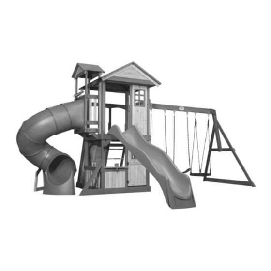
TACOMA FALLS SWING SET
Model # 1902022B
assembly time may vary based on skill level
For the most up to date assembly manual,
to register your set, or to order replacement parts please visit
www.backyarddiscovery.com
YOU NEED TO ORDER REPLACEMENT PARTS.
-20
Owner's Manual & Assembly Instructions
average 2 person assembly time
average tube slide assembly time
MANUFACTURED BY:
Backyard Discovery
3305 Airport Drive
Pittsburg, KS 66762
800-856-4445
Advertisement
Table of Contents

Related Manuals for Backyard Discovery TACOMA FALLS


Summary of Contents for Backyard Discovery TACOMA FALLS
- Page 1 For the most up to date assembly manual, to register your set, or to order replacement parts please visit www.backyarddiscovery.com SAVE THIS ASSEMBLY MANUAL FOR FUTURE REFERENCE IN THE EVENT THAT YOU NEED TO ORDER REPLACEMENT PARTS. Made in China INS-1902022B-TACOMA FALLS-ENG 11-...
- Page 2 INSTALLATION SERVICES AVAILABLE! Need a helping hand? Let our team of professionals handle the installation for you! *Installation services are only available to U.S. customers. With Go Configure, we bring you 18 years of experience right to your doorstep. We service a wide array of indoor and outdoor recreation products that most consumers don’t have the time or ability to deliver &...
- Page 3 Owner’s Manual Please Read This Before Starting Assembly MISSING A PART? CALL US BEFORE GOING BACK TO THE STORE The store where you made your purchase does not stock parts for this item. If you have assembly questions or you are missing or have damaged parts, please call you can also visit www.backyarddiscovery.com or e-mail customerservice@backyarddiscovery.com...
- Page 4 Botanical, Adventure Playsets, and Leisure Time Products. Backyard Discovery warrants that this product is free from defect in materials and workmanship for a period of one (1) year from the original date of purchase. This one (1) year warranty covers all parts including wood, hardware, and accessories. All wood carries a fi ve (5) year pro-rated warranty against rot and decay. Refer to the schedule below for charges associated with replacement of parts under this Limited Warranty.
- Page 5 Operating Instructions and Safety Warnings WARNING: BURN HAZARD NOTE: Your Children’s Safety Is Our #1 Concern! MUST NOT LOOK DO NOT DRESS CHILDREN APPROPRIATELY. DO NOT NEVER REQUIRED. MOST SERIOUS INJURIES AND DEATHS ON PLAYGROUND EQUIPMENT NEVER HAVE OCCURRED WHILE CHILDREN WERE UNSUPERVISED! DO NOT DO NOT DO NOT...
- Page 6 Owner’s Manual Please Read This Before Starting Assembly Positioning Your Playcenter Suggested Playground Surfacing • The playcenter is designed to be installed on a • Do not install home playground equipment over level surface by an adult with an adult helper. concrete, asphalt, packed earth, grass, carpet, or Place in a fl at area of your yard to minimize ground any other hard surface.
- Page 7 Owner’s Manual Please Read This Before Starting Assembly APPENDIX A The following information is from the United States X3.1.3.2 Do not install loose-fi ll surfacing over hard surfaces such as concrete or asphalt. Consumer Product Safety Commission’s Information X3.1.4 Poured-In-Place Surfaces or Pre-Manufactured Sheet for playground surfacing material;...
- Page 8 Check all moving parts including swing seats, third party person or service to assemble this product. ropes, cables, and chains for wear, rust, or other Backyard Discovery assumes no responsibility or deterioration. Replace as needed. liability for any charge incurred by the Customer for any assembly services’...
- Page 9 About Our Wood Backyard Discovery uses 100% Cedar (C. Lanceolata) wood. Although we take great care in selecting the best quality lumber available, wood is still a product of nature and susceptible to weathering which can change the appearance of your set.
- Page 10 Owner’s Manual Assembly Tips Protrusion Hazard Incorrect Correct If you see exposed threads and your bolt protrudes beyond the T-Nut you may have over tightened the bolt or used incorrect hardware. If you’ve overtightened, remove the bolt and add washers to eliminate the protrusion.
- Page 11 Owner’s Manual Assembly Tips ASSEMBLY TIP: Keep and eye out for these boxes which will contain helpful pictures and information making the assembly process as quick and painless as possible. Sorting Wood When removing the wood from the boxes we recommend arranging them by part number before you begin assembly.
- Page 12 Tools Required for Installation Owner's Manual When you see this icon you will need You will need to make sure that your a socket wrench. Th e icons below show assembly is square before tightening the size of attachments needed for your bolts.
- Page 13 Basic Setup Dimensions & Assembly Notes Owner's Manual Place the set on level ground, not less than 6'- 7" [2 m] from any structure or obstruction such as a fence, garage, house, overhanging branches, laundry lines, or electrical wires. • While assembling unit, take time before and after each phase to make sure fort is level.
- Page 14 Wood Components (Not to Scale) Parts Identification SWING BEAM - W4L12440 3 3/8"x5 1/4"x89 1/2" (86x134x2274) (x1) SB 9" BLOCK - W4L12441 3 3/8"x5 1/4"x9" (86x134x228) (x1) POST - W4L12286 3"x3"x89 1/2" (76x76x2274) (x1) POST - W4L12287 3"x3"x89 1/2" (76x76x2274) (x1) POST - W4L12288 3"x3"x89 1/2"...
- Page 15 Wood Components (Not to Scale) Parts Identification WALL UPRIGHT - W4L12405 1 3/8"x2 3/8"x57 3/4" (36x60x1467) (x2) DOOR STOP - W4L12501 1 3/8"x1 3/8"x3 7/8" (36x36x100) (x2) GROUND BOARD - W4L12290 1"x5 1/4"x70 3/4" (24x134x1798) (x1) GROUND BOARD - W4L12291 1"x5 1/4"x72 1/4"...
- Page 16 Wood Components (Not to Scale) Parts Identification DECK SUPPORT - W4L12403 DECK SUPPORT - W4L12306 1"x3 3/8"x13 5/8" (24x86x345) 1"x3 3/8"x47" (24x86x1194) (x2) (x2) DECK SUPPORT - W4L12410 DECK SUPPORT - W4L12414 1"x3 3/8"x11 3/4" (24x86x297) (x1) 1"x3 3/8"x30 3/8" (24x86x772) (x1) DECK SUPPORT - W4L12408 1"x3 3/8"x30 3/8"...
- Page 17 Wood Components (Not to Scale) Parts Identification COUNTER TOP - W4L12321 COUNTER TOP - W4L12320 5/8"x5 1/4"x32 3/4" (16x134x832) 5/8"x5 1/4"x32 3/4" (16x134x832) (x1) (x1) FACIA - W4L12430 COUNTER TOP - W4L12423 5/8"x5 1/4"x51" (16x134x1296) (x1) 5/8"x5 1/4"x22 1/2" (16x134x570) (x1) DECK BOARD - W4L12409 5/8"x3 3/8"x32 1/4"...
- Page 18 Wood Components (Not to Scale) Parts Identification ROCK BOARD - W4L12499 ROCKWALL CLEAT - W4L12965 5/8"x2 3/8"x27 3/4" (16x60x706) 5/8"x2 3/8"x54 1/2" (16x60x1385) (x1) (x1) WINDOW TRIM - W4L12419 WINDOW TRIM - W4L12420 WINDOW TRIM - W4L12435 5/8"x1 3/8"x14 1/4" (16x34x361) 5/8"x1 3/8"x11 7/8"...
- Page 19 Wood Components (Not to Scale) Parts Identification ROOF PANEL - W2A02754 ROOF PANEL - W2A02756 1 3/8"x19 7/16"x63 5/8" (35x494x1616) (x1) 1 3/8"x20 3/8"x21 5/16" (35x517x541) (x2) ROOF PANEL - W2A02755 1 3/8"x19 7/16"x63 5/8" (35x494x1616) (x1) WALL PANEL - W2A02751 WALL PANEL - W2A02748 (x2) 1 1/16"x20 7/16"x36 1/2"...
- Page 20 Hardware Components Parts Identification H100197 H100458 LAG SCREW WH BLK LAG SCREW WH BLK (x27) (x3) 5/16x2 5/16x2 1/2 H100201 SCREW PFH BLK H100797 SCREW PWH BLK (x39) 8x2-1/2 (x20) H100391 H100202 SCREW PWH BLK SCREW PFH BLK (x15) (x26) 8x5/8 H100382 SCREW PFH BLK...
- Page 21 Hardware Components Parts Identification H100363 BOLT WH BLK (x1) 5/16X6 H100396 BOLT WH BLK (x9) 5/16x1/2 H100534 BOLT WH BLK (x2) 5/16x4 1/2 H100468 BOLT WH BLK 5/16x1 H100415 BOLT WH BLK (x46) 5/16x3 3/4 H100407 BOLT WH BLK (x8) 5/16x1 1/2 H100503 BOLT WH BLK...
- Page 22 Hardware Components Parts Identification H100004 NUT BARREL WH H100192 NUT BARREL WH BLK H100193 NUT BARREL WH BLK H100469 NUT BARREL WH BLK (x3) (x2) (x39) 5/16 x 5/8 5/16x1-1/2 5/16x7/8 (x7) 5/16x5/8 H100398 T-NUT BLK H100804 T-NUT H100379 T-NUT BLK (x26) (x20) 8/32...
- Page 23 Accessories (Not to Scale) Parts Identification A4M00927 QUICK LINK SD (x4) A100164 A100118 BYD ID TAG (LARGE) AGES 3-10 HAND GRIP METAL GREEN 381 c/c (x1) (x3) A4M00926 CARABINER SD (x6) A100325 SWING BEAM EXTENSION BRACKET-LEFT A4M01045 (x1) BELL ASSEMBLY A4M00993 A100326 EXTENDED SWING BEAM BRACKET...
- Page 24 Accessories (Not to Scale) Parts Identification A6P00037 A6P00362 GREEN HC ROCK #2 26" HD BELT SWING (x12) (x2) A6P00274 KNOB - DR.BRN (x1) A6P00096 Telescope (x1) A6P00330 INDUCTIVE BURNER KIT A6P00331 BLENDER (x1) A6P00333 FAUCET (x1) A6P00335 STOVE BASE A6P00332 (x1) PREMIUM SINK (x1)
- Page 25 Accessories (Not to Scale) Parts Identification A6P00336 BOIL POT (x1) A6P00337 A6P00338 POT/PAN LID FRY PAN (x2) (x1) A6P00339 A6P00340 SPATULA LADLE (x1) (x1) A6P00324 CHALK BOARD LARGE (x1)
- Page 26 Accessories (Not to Scale) Parts Identification A100287 SLIDE VF 10 FT (x1) 26" WEB SWING (x1) A100314 "A" REVISION TAG (x1)
- Page 27 1 3/8 in [34 mm] POST - W4L12288 UPPER POST - W4L12428 3"x3"x21 1/4" (76x76x541) 3"x3"x89 1/2" (76x76x2274) (x1) (x1) FACIA - W4L12401 POST - W2A02758-1 1"x3 3/8"x56 3/4" (24x86x1440) (x1) UPPER POST - W4L12397 3"x3"x89 1/2" (76x76x2274) (x1) 3"x3"x21 1/4" (76x76x541) (x1) DECK RAIL - W4L12297 UPPER DECK RAIL - W4L12301...
- Page 28 1 3/8 in [34 mm] UPPER POST - W4L12428 POST - W4L12286 3"x3"x21 1/4" (76x76x541) 3"x3"x89 1/2" (76x76x2274) (x1) (x1) FACIA - W4L12400 1"x3 3/8"x56 3/4" (24x86x1440) (x1) UPPER POST - W4L12397 POST - W4L12287 3"x3"x89 1/2" (76x76x2274) 3"x3"x21 1/4" (76x76x541) (x1) (x1) 9 1/2 in...
- Page 29 20 1/8 in [512 mm] FACIA - W4L12402 GROUND BOARD - W4L12290 DECK RAIL - W4L12294 1"x3 3/8"x49 1/8" (24x86x1248) (x1) 1"x5 1/4"x70 3/4" (24x134x1798) (x1) 1"x5 1/4"x51" (24x134x1296) (x1) H100379 H100415 BOLT WH BLK T-NUT BLK H100198 WASHER LOCK EXT BLK (x10) (x10) 5/16x3 3/4...
- Page 30 UPPER DECK RAIL - W4L12299 GROUND BOARD - W4L12292 DECK RAIL - W4L12296 1"x5 1/4"x50 1/8" (24x134x1272) 1"x5 1/4"x49 1/8" (24x134x1248) 1"x5 1/4"x51" (24x134x1296) (x1) (x1) (x1) H100503 BOLT WH BLK H100198 WASHER LOCK EXT BLK (x4) 5/16x3-1/2 H100197 LAG SCREW WH BLK (x12) 8x19 (x4)
- Page 31 FACIA - W4L12427 H100201 SCREW PFH BLK H100379 T-NUT BLK 1"x3 3/8"x49 1/8" (24x86x1248) (x4) 8x2-1/2 (x1) (x2) 5/16 FLUSH FLUSH FOR EASE OF ASSEMBLY INSTALL SHOWN T-NUTS AT THIS TIME. NOTE THESE WILL BE USED IN A LATER STEP.
- Page 32 DECK SUPPORT - W4L12308 DECK SUPPORT - W4L12311 H100200 SCREW PFH BLK 1"x1 3/8"x41" (24x34x1040) 1"x1 3/8"x3" (24x34x76) (x16) (x2) 8x1 1/2 (x4) REPEAT THIS ON BOTH SIDES AS SHOWN 1 7/8 in [48 mm] INSIDE VIEW...
- Page 33 H100457 BOLT WH BLK (x2) 5/16x2 H100197 LAG SCREW WH BLK BRACE - W4L12312 (x3) 5/16x2 1/2 1 3/8"x3 3/8"x13 5/8" (36x86x347) (x3) H100198 WASHER LOCK EXT BLK (x6) 8x19 H100205 BOLT WH BLK H100379 T-NUT BLK (x1) 5/16x2-1/4 (x3) 5/16...
- Page 34 H100201 SCREW PFH BLK DECK SUPPORT - W4L12306 (x8) 8x2-1/2 1"x3 3/8"x47" (24x86x1194) (x2)
- Page 35 CROSS SUPPORT - W4L12315 H100378 BOLT WH BLK H100468 BOLT WH BLK 1"x5 1/4"x65 1/4" (24x134x1658) (x1) (x6) 5/16x1 3/4 (x1) 5/16x1 CROSS SUPPORT - W4L12314 1"x5 1/4"x65 1/4" (24x134x1658) (x1) H100198 WASHER LOCK EXT BLK H100379 T-NUT BLK (x7) (x7) 8x19 5/16...
- Page 36 H100378 BOLT WH BLK H100197 LAG SCREW WH BLK (x2) 5/16x1 3/4 (x4) 5/16x2 1/2 CROSS BRACE - W4L12966 1"x5 1/4"x17" (24x134x430) (x2) H100379 T-NUT BLK H100198 WASHER LOCK EXT BLK (x2) 5/16 (x6) 8x19...
- Page 37 21 7/8 in [556 mm] H100192 NUT BARREL WH BLK H100407 BOLT WH BLK (x2) (x2) 5/16x7/8 5/16x1 1/2 WALL UPRIGHT - W4L12303 1"x2 3/8"x51 3/4" (24x60x1314) (x1) H100199 WASHER LOCK EXT BLK H100198 WASHER LOCK EXT BLK (x2) (x2) 12x19 8x19 INSTALL J1 BOARD WITH...
- Page 38 LOWER RAIL - W4L12304 H100458 H100198 LAG SCREW WH BLK WASHER LOCK EXT BLK (x2) (x2) 5/8"x3 3/8"x47" (16x86x1194) 5/16x2 8x19 (x1)
- Page 39 H100198 WASHER LOCK EXT BLK H100197 LAG SCREW WH BLK (x3) 8x19 (x1) 5/16x2 1/2 BRACE - W4L12500 1 3/8"x3 3/8"x37 3/4" (36x86x959) (x1) H100205 BOLT WH BLK H100379 T-NUT BLK (x2) 5/16x2-1/4 (x2) 5/16 NOTE PILOT HOLE...
- Page 40 H100200 SCREW PFH BLK H100198 WASHER LOCK EXT BLK H100468 BOLT WH BLK (x2) 8x1 1/2 LOWER RAIL - W4L12305 (x2) (x1) 8x19 5/16x1 5/8"x3 3/8"x24 7/8" (16x86x632) (x1) H100199 WASHER LOCK EXT BLK COUNTER SUPPORT - W4L12424 (x1) H100458 12x19 LAG SCREW WH BLK H100192...
- Page 41 PICKET - W4L12317 H100380 SCREW PFH BLK PICKET - W4L12316 PICKET - W4L12323 (x24) 5/8"x2 7/8"x21" (16x74x533) 8x1 1/8 5/8"x3 3/8"x21" (16x86x533) (x1) 5/8"x3 3/8"x21" (16x86x533) (x3) (x2) NOTE: EVENLY SPACE ANY GAPS BETWEEN BOARDS. FLUSH NOTE HOLE LOCATIONS AND BOARD ORIENTATION ON M10 BOARDS.
- Page 42 5 in [126 mm] H100380 SCREW PFH BLK PICKET - W4L12316 PICKET - W4L12395 (x24) 8x1 1/8 5/8"x3 3/8"x21" (16x86x533) 5/8"x3 3/8"x21" (16x86x533) (x4) (x2) 3 in [77 mm] FLUSH NOTE HOLE LOCATIONS AND BOARD ORIENTATION ON M8 PICKETS.
- Page 43 COUNTER TOP SUPPORT - W4L12322 1"x5 1/4"x9 7/8" (24x134x250) H100197 LAG SCREW WH BLK (x3) H100198 WASHER LOCK EXT BLK (x1) 5/16x2 1/2 (x1) 8x19 COUNTER TOP SUPPORT - W4L12425 H100391 SCREW PFH BLK 1"x5 1/4"x9 7/8" (24x134x250) (x8) (x1) INSIDE VIEW USE THE PILOT HOLES TO INSTALL THE COUNTER...
- Page 44 COUNTER TOP - W4L12320 COUNTER TOP - W4L12321 5/8"x5 1/4"x32 3/4" (16x134x832) 5/8"x5 1/4"x32 3/4" (16x134x832) (x1) (x1) H100200 SCREW PFH BLK (x16) 8x1 1/2 COUNTER TOP - W4L12319 COUNTER TOP - W4L12318 5/8"x5 1/4"x23 5/8" (16x134x600) 5/8"x5 1/4"x23 5/8" (16x134x600) (x1) (x1)
- Page 45 H100380 SCREW PFH BLK (x4) 8x1 1/8 COUNTERTOP CLEAT - W4L12426 5/8"x2 3/8"x5 7/8" (16x60x150) (x1) CENTER SUPPORT BETWEEN THE SHOWN COUNTER TOP BOARDS.
- Page 46 H100200 SCREW PFH BLK COUNTER TOP - W4L12423 (x3) 8x1 1/2 5/8"x5 1/4"x22 1/2" (16x134x570) (x1) ALIGN THE PILOT HOLES TO LOCATE K7 BOARD.
- Page 47 H100807 H100804 SCREW POH BLK H100806 T-NUT SCREW POH BLK (x9) 8/32x1 (x9) 8/32x1 1/8 (x18) 8/32 DOOR PANEL - W2A02757 1 1/8"x16 1/2"x43 7/8" (27x493x1072) (x1) A4M00624 A4M00994 HINGE (DOOR, SPRING LOADED) HINGE (DOOR, NON-SPRING LOADED) (x2) (x1) START BY ATTACHING THE HINGES TO THE DOOR FIRST.
- Page 48 H100382 SCREW PFH BLK (x1) 8x1 3/4 A6P00274 KNOB - DR.BRN (x1) NOTE PILOT HOLE...
- Page 49 WINDOW TRIM - W4L12436 H100816 WINDOW TRIM - W4L12435 SCREW PFH BLK (x8) 8x7/8 5/8"x1 3/8"x10 3/8" (16x34x265) 5/8"x1 3/8"x12" (16x34x306) (x2) (x2) H100387 SCREW PFH BLK WINDOW TRIM - W4L12438 WINDOW TRIM - W4L12437 (x4) 8x1-1/4 5/8"x1 3/8"x12" (16x34x306) (x1) 5/8"x1 3/8"x13 1/8"...
- Page 50 DOOR STOP - W4L12501 H100201 SCREW PFH BLK 1 3/8"x1 3/8"x3 7/8" (36x36x100) (x2) (x4) 8x2-1/2 MOUNT THE DOOR STOPS USING THE DIMENSIONS AS SHOWN.
- Page 51 FLOOR PANEL - W2A02747 (x1) 1 1/4"x14 5/8"x49 1/16" (32x372x1247) H100200 SCREW PFH BLK (x60) 8x1 1/2 FLOOR PANEL - W2A02746 (x1) 1 1/4"x20 7/16"x49 1/16" (32x519x1247) FLOOR PANEL - W2A02749 1 1/4"x11 7/8"x49 1/16" (32x302x1247) (x1) PLACE FLOOR PANELS AS SHOWN FIRST.
- Page 52 H100198 WASHER LOCK EXT BLK (x4) 8x19 WALL UPRIGHT - W4L12398 1 3/8"x2 3/8"x60 3/8" (36x60x1533) (x2) H100205 BOLT WH BLK (x4) 5/16x2-1/4 H100379 T-NUT BLK (x4) 5/16 NOTE THE DIAGRAM TO THE RIGHT. NOTE HOW THE F1 BOARDS MIRROR EACH OTHER WITH THE SHOWN HOLES BEING CLOSER TO THE INSIDE OPENING.
- Page 53 DECK SUPPORT - W4L12408 H100457 BOLT WH BLK 1"x3 3/8"x30 3/8" (24x86x772) (x1) (x2) 5/16x2 H100199 WASHER LOCK EXT BLK H100192 NUT BARREL WH BLK A100340 (x2) 12x19 L BRACKET 2.5x38x50x55 (x2) (x2) 5/16x7/8 2 1/8 in [55 mm] THE BRACKET ORIENTATION IS CRITICAL.
- Page 54 2 in [51 mm] H100396 BOLT WH BLK (x2) 5/16x1/2 DECK SUPPORT - W4L12403 1"x3 3/8"x13 5/8" (24x86x345) (x2) H100192 NUT BARREL WH BLK H100199 WASHER LOCK EXT BLK (x2) 5/16x7/8 (x2) 12x19 NOTE HOLE ORIENTATION...
- Page 55 H100205 BOLT WH BLK H100198 WASHER LOCK EXT BLK (x2) 5/16x2-1/4 (x4) 8x19 BRACE - W4L12418 1 3/8"x3 3/8"x13 7/8" (36x86x351) (x2) H100379 T-NUT BLK H100457 BOLT WH BLK (x2) 5/16 (x2) 5/16x2 AT THIS TIME YOU WILL MOUNT THE BRACES USING THE T-NUTS THAT WERE PREVIOUSLY INSTALLED.
- Page 56 Phase 1 H100197 LAG SCREW WH BLK (x4) 5/16x2 1/2 WALL UPRIGHT - W4L12405 1 3/8"x2 3/8"x57 3/4" (36x60x1467) (x2) H100379 T-NUT BLK H100198 WASHER LOCK EXT BLK (x2) 5/16 (x4) 8x19 PRE-INSTALL T-NUTS NOTE PILOT HOLES USED BELOW START BY INSTALLING THE T-NUTS AS SHOWN.
- Page 57 Phase 1 H100198 WASHER LOCK EXT BLK DECK SUPPORT - W4L12414 H100205 BOLT WH BLK (x2) 8x19 (x2) 1"x3 3/8"x30 3/8" (24x86x772) 5/16x2-1/4 (x1) MOUNT H4 USING THE T-NUTS INSTALLED ON THE PREVIOUS STEP.
- Page 58 Phase 1 H100396 BOLT WH BLK TOP RAIL BOARD - W4L12406 H100197 LAG SCREW WH BLK H100468 BOLT WH BLK (x2) 5/16x1/2 (x4) 5/16x2 1/2 (x2) 1"x3 3/8"x13 5/8" (24x86x345) 5/16x1 (x2) H100199 H100192 NUT BARREL WH BLK H100198 WASHER LOCK EXT BLK WASHER LOCK EXT BLK A100340 (x4)
- Page 59 Phase 1 H100198 WASHER LOCK EXT BLK H100205 BOLT WH BLK (x2) 8x19 (x2) 5/16x2-1/4 TOP RAIL BOARD - W4L12404 1"x3 3/8"x30 3/8" (24x86x772) (x1) H100379 T-NUT BLK (x2) 5/16...
- Page 60 Phase 1 H100201 SCREW PFH BLK DECK SUPPORT - W4L12410 (x4) 8x2-1/2 1"x3 3/8"x11 3/4" (24x86x297) (x1) USE THE PILOT HOLES IN H3 TO ALIGN AND MOUNT IT.
- Page 61 Phase 1 DECK BOARD - W4L12409 DECK BOARD - W4L12411 5/8"x3 3/8"x32 1/4" (16x86x820) 5/8"x3 3/8"x32 1/4" (16x86x820) (x1) (x2) H100200 SCREW PFH BLK (x22) 8x1 1/2 DECK BOARD - W4L12412 5/8"x3 3/8"x32 1/4" (16x86x820) (x1) USING THE PRE-DRILLED HOLES MOUNT THE FLOOR BOARDS WITH THE PROVIDED SCREWS.
- Page 62 Phase 1 H100468 BOLT WH BLK H100192 NUT BARREL WH BLK (x2) (x2) 5/16x1 5/16x7/8 A100340 L BRACKET 2.5x38x50x55 (x2) H100199 WASHER LOCK EXT BLK (x2) 12x19 2 1/8 in [55 mm] THE BRACKET ORIENTATION IS CRITICAL. PLEASE ORIENTATE WITH DIMENSION BELOW AS SHOWN.
- Page 63 Phase 1 H100396 BOLT WH BLK H100197 LAG SCREW WH BLK H100192 NUT BARREL WH BLK (x2) 5/16x1/2 (x4) 5/16x2 1/2 (x2) 5/16x7/8 TOP RAIL BOARD - W4L12406 1"x3 3/8"x13 5/8" (24x86x345) (x2) H100198 H100199 WASHER LOCK EXT BLK WASHER LOCK EXT BLK (x4) (x2) 12x19...
- Page 64 Phase 1 H100198 WASHER LOCK EXT BLK H100205 BOLT WH BLK (x4) 8x19 (x4) 5/16x2-1/4 SLIDE ATTACHMENT BOARD - W4L12407 1"x2 3/8"x27 5/8" (24x60x703) (x2) H100379 T-NUT BLK (x4) 5/16...
- Page 65 Phase 1 H100407 BOLT WH BLK H100192 NUT BARREL WH BLK H100378 BOLT WH BLK (x1) 5/16x1 1/2 (x1) (x1) 5/16x7/8 5/16x1 3/4 WALL UPRIGHT - W4L12302 1"x2 3/8"x52 1/2" (24x60x1334) (x1) H100379 T-NUT BLK H100199 H100198 WASHER LOCK EXT BLK WASHER LOCK EXT BLK (x1) 5/16...
- Page 66 Phase 1 19 3/8 in [492 mm] H100192 NUT BARREL WH BLK H100396 BOLT WH BLK H100378 BOLT WH BLK (x1) 5/16x7/8 (x2) 5/16x1/2 WALL UPRIGHT - W4L12396 (x2) 5/16x1 3/4 1"x2 3/8"x36 1/2" (24x60x927) (x1) H100379 T-NUT BLK H100198 H100199 WASHER LOCK EXT BLK WASHER LOCK EXT BLK...
- Page 67 Phase 2 LEFT UPRIGHT - W4L12490 1 3/8"x3 3/8"x58" (36x86x1474) (x1) H100201 SCREW PFH BLK (x8) 8x2-1/2 LADDER RUNG - W4L12492 1"x3 3/8"x19 1/4" (24x86x489) (x4)
- Page 68 Phase 2 H100201 SCREW PFH BLK MIDDLE UPRIGHT - W4L12491 (x8) 8x2-1/2 1 3/8"x3 3/8"x58" (36x86x1474) (x1)
- Page 69 Phase 2 H100200 SCREW PFH BLK REAR SUPPORT - W4L12493 (x4) 8x1 1/2 5/8"x3 3/8"x21 1/4" (16x86x541) (x1)
- Page 70 Phase 2 H100391 SCREW PFH BLK (x6) RIGHT UPRIGHT - W4L12495 1 3/8"x3 3/8"x58" (36x86x1474) (x1) H100379 T-NUT BLK ATTACHMENT BOARD - W4L12494 (x2) 5/16 5/8"x4"x49 1/8" (16x102x1248) (x1) ADD T-NUTS AS SHOWN PRIOR TO INSTALLING THE Y2 BOARD. NOTE HOLE AND BOARD ORIENTATION BEFORE ADDING T-NUTS.
- Page 71 Phase 2 ROCK BOARD - W4L12496 ROCK BOARD - W4L12499 H100398 T-NUT BLK 5/8"x3 3/8"x27 3/4" (16x86x706) 5/8"x2 3/8"x27 3/4" (16x60x706) (x8) (x1) (x24) ROCK BOARD - W4L12497 ROCK BOARD - W4L12498 5/8"x3 3/8"x27 3/4" (16x86x706) 5/8"x3 3/8"x27 3/4" (16x86x706) (x4) (x4) H100200...
- Page 72 Phase 2 H100380 SCREW PFH BLK ROCKWALL CLEAT - W4L12965 (x11) 8x1 1/8 5/8"x2 3/8"x54 1/2" (16x60x1385) (x1) PLACE AND CENTER N5 BOARD AS SHOWN.
- Page 73 Phase 2 H100473 WASHER LOCK INT BLK H100489 BOLT PTH BLK A6P00037 GREEN HC ROCK #2 (x24) (x24) 8x15 1/4x3/4 (x12) NOTE ARROW SHOULD FACE UP. INSTALL ROCKS USING THE SHOWN HARDWARE WITH THE T-NUTS THAT WERE PRE-INSTALLED FROM STEP 5 OF THIS PHASE.
-
Page 74: Table Of Contents
Phase 2 H100379 T-NUT BLK H100205 BOLT WH BLK H100198 WASHER LOCK EXT BLK (x4) 5/16 (x4) 5/16x2-1/4 (x7) 8x19 H100468 BOLT WH BLK H100192 NUT BARREL WH BLK (x1) 5/16x1 (x1) 5/16x7/8 ROCK WALL ASSEMBLY H100407 H100199 WASHER LOCK EXT BLK BOLT WH BLK FROM THE PREVIOUS STEP (x1) - Page 75 Phase 3 H100200 SCREW PFH BLK TOP RAIL BOARD - W4L12417 (x5) 8x1 1/2 1"x3 3/8"x25 5/8" (24x86x652) (x1) FLUSH...
- Page 76 Phase 3 H100380 SCREW PFH BLK (x8) 8x1 1/8 WALL BOARD - W4L12399 5/8"x5 1/4"x52 3/8" (16x134x1329) (x2) NOTE BOARD ORIENTATION. BOARD ONLY FITS ONE WAY.
- Page 77 Phase 3 H100380 SCREW PFH BLK (x24) 8x1 1/8 WALL PANEL - W2A02751 1 1/16"x20 7/16"x36 1/2" (27x519x927) (x2)
- Page 78 Phase 3 H100380 SCREW PFH BLK (x10) 8x1 1/8 WALL PANEL - W2A02748 1 1/16"x15 15/16"x52 3/8" (27x405x1331) (x1)
- Page 79 Phase 3 WINDOW FRAME - W4L12421 WINDOW TRIM - W4L12419 H100395 SCREW PFH BLK H100816 SCREW PFH BLK (x2) 8x3/4 (x8) 1"x1 3/8"x16 7/8" (24x34x429) 5/8"x1 3/8"x14 1/4" (16x34x361) 8x7/8 (x1) (x2) WINDOW TRIM - W4L12420 WINDOW FRAME - W4L12422 H100200 SCREW PFH BLK 5/8"x1 3/8"x11 7/8"...
- Page 80 Phase 3 UPPER PICKET - W4L12416 H100380 SCREW PFH BLK 5/8"x2 3/8"x26 1/4" (16x60x666) (x16) 8x1 1/8 (x4) FOLLOW THESE STEPS ON BOTH SIDES. INSIDE VIEW 2 1/8 in [55 mm] 5/8 in [16 mm] 2 1/8 in [55 mm]...
- Page 81 Phase 3 FACIA - W4L12431 5/8"x4 3/8"x51" (16x112x1296) (x1) H100200 SCREW PFH BLK (x12) 8x1 1/2 FACIA - W4L12430 5/8"x5 1/4"x51" (16x134x1296) (x1)
- Page 82 Phase 4 ROOF CLEAT - W4L12433 5/8"x2 3/8"x3 15/16" (16x60x100) (x1) H100387 SCREW PFH BLK (x4) 8x1-1/4 ROOF JOIST - W4L12432 H100382 SCREW PFH BLK 1"x3 3/8"x30 3/8" (24x86x770) (x4) (x2) 8x1 3/4 OPTION: IF YOU DON'T HAVE A HELPER YOU CAN ASSEMBLE THE ROOF JOISTS ON THE GROUND FORMING THE PEAK AND THEN MOUNT...
- Page 83 Phase 4 H100380 SCREW PFH BLK FACIA BOARD - W4L12967 (x12) 8x1 1/8 5/8"x3 3/8"x34 5/8" (16x86x880) (x4) GUSSET PANEL - W2A02752 5/8"x47"x12 3/4" (16x1194x324) (x2) DO THESE STEPS TWICE MAKE SURE THE CORNERS OR POINTS ALIGN AS SHOWN. FOR EASE OF ASSEMBLY: LAY M16 BOARDS ON LEVEL GROUND AND ALIGN A GP1 PANEL ON TOP.
-
Page 84: Bolt Wh Blk
Phase 4 H100534 BOLT WH BLK (x2) 5/16x4 1/2 GUSSET PANEL FROM PREVIOUS STEP H100407 BOLT WH BLK (x2) (x2) 5/16x1 1/2 FACIA - W4L12429 H100198 WASHER LOCK EXT BLK H100379 T-NUT BLK 1"x3 3/8"x51" (24x86x1296) (x1) (x4) (x4) 8x19 5/16 (x1) -
Page 85: Bolt Wh Blk
Phase 4 H100194 BOLT WH BLK (x4) 5/16x2 1/2 GUSSET PANEL - W2A02750 1 1/16"x12 3/4"x34 9/16" (27x326x874) (x2) H100198 H100379 WASHER LOCK EXT BLK T-NUT BLK (x4) (x4) 8x19 5/16 TOP RAIL BOARD - W4L12434 5/8"x3 3/8"x30 3/8" (16x86x772) (x2) - Page 86 Phase 4 H100200 SCREW PFH BLK (x12) 8x1 1/2 ROOF PANEL - W2A02756 (x2) 1 3/8"x20 3/8"x21 5/16" (35x517x541) USE A HELPER TO HOLD THE PANELS AND TO MAKE SURE THE PANELS ARE CENTERED ON THE PEAK DURING ASSEMBLY. NOTE PILOT HOLES...
- Page 87 Phase 4 H100200 SCREW PFH BLK (x10) 8x1 1/2 ROOF PANEL - W2A02753 (x2) 1 3/8"x15 13/16"x63 5/8" (35x401x1616) USE A HELPER TO HOLD THE PANELS AND HELP MAKE SURE THE PANELS ARE CENTERED ON THE PEAK DURING ASSEMBLY.
- Page 88 Phase 4 H100200 SCREW PFH BLK (x8) 8x1 1/2 ROOF PANEL - W2A02754 ROOF PANEL - W2A02755 1 3/8"x19 7/16"x63 5/8" (35x494x1616) (x1) 1 3/8"x19 7/16"x63 5/8" (35x494x1616) (x1) INSTALL THE RP3 PANEL USING THE SAME STEPS AS SHOWN ON THE RP2 PANEL. NOTE HOW PANELS OVERLAP.
-
Page 89: H100379 T-Nut Blk
Phase 5 H100416 BOLT WH BLK (x4) 5/16x3 H100468 BOLT WH BLK (x2) 5/16x1 A100118 HAND GRIP METAL GREEN 381 c/c (x3) H100379 T-NUT BLK (x6) 5/16... - Page 90 Phase 6 SB 9" BLOCK - W4L12441 3 3/8"x5 1/4"x9" (86x134x228) (x1) A100325 SWING BEAM EXTENSION BRACKET-LEFT (x1) A4M00993 EXTENDED SWING BEAM BRACKET (x2) SWING BEAM - W4L12440 3 3/8"x5 1/4"x89 1/2" (86x134x2274) (x1) A100326 SWING BEAM EXTENSION BRACKET-RIGHT (x1) H100416 BOLT WH BLK (x10)
- Page 91 Phase 6 H100665 BOLT HEX SD (x12) 3/8x5 3/4 H100700 T-NUT SD A4M00926 H100708 WASHER LOCK INT SD H100703 WASHER FLAT SD SINGLE DUCTILE HANGER SD (x12) (x12) (x12) 10x18 11x25...
- Page 92 Phase 6 SWING BEAM SUPPORT - W4L12439 S.B. ANGLE BRACE - W4L12444 1 3/8"x3 3/8"x88 3/4" (36x86x2254) 3 3/8"x3 3/8"x49 3/8" (86x86x1254) (x1) (x2) S.B. END SUPPORT - W4L12443 GROUND BOARD - W4L12442 1 3/8"x3 3/8"x44 1/8" (36x86x1120) 1"x5 1/4"x86 3/4" (24x134x2202) (x1) H100363 BOLT WH BLK...
- Page 93 Phase 6 H100416 BOLT WH BLK (x2) H100192 5/16x3 NUT BARREL WH BLK (x2) 5/16x7/8...
- Page 94 Phase 6 H100481 BOLT HEX BLK (x4) 5/16x1 1/4 SWING BEAM ASSEMBLY FROM PREVIOUS STEPS H100477 WASHER SPLIT BLK (x4) 5/16 H100478 WASHER FLAT BLK (x4) 8x27 INSTALL HARDWARE USING THE T-NUTS THAT WERE PREVIOUSLY INSTALLED. SWING BEAM ASSEMBLY...
-
Page 95: (X4)
Phase 6 A100164 BYD ID TAG (LARGE) AGES 3-10 A4M00927 (x1) QUICK LINK SD (x4) H100202 SCREW PWH BLK A4M01005 CHAIN GREEN 7mm x 1452mm (57in) (x4) (x4) 8x5/8 26" WEB SWING (x1) A6P00362 26" HD BELT SWING (x2) - Page 96 WEB SWING SETUP INSTRUCTIONS: FOLLOW INSTRUCTIONS BELOW BEFORE USING THE WEB SWING. H100832 BOLT PTH H100831 NUT BARREL PTH BLK 1/4x3/4 1/4x3/4 IMPORTANT: SLIDE ROPE LOOPS OVER TUBE ENDS FIRST! SLIDE NARROW END OF TUBES INTO LARGER OPENING AFTER SLIDING ROPE LOOPS ONTO TUBES.
- Page 97 Phase 7 H100202 SCREW PWH BLK (x4) 8x5/8 H100385 SCREW PFH BLK A6P00333 FAUCET (x2) A6P00332 (x1) PREMIUM SINK (x1)
- Page 98 STEP 2 Phase 7 A6P00330 INDUCTIVE BURNER KIT A6P00335 STOVE BASE (x1) "AA" BATTERY (x3) (Not Included) ASSEMBLY NOTE: ALWAYS WASH TOYS BEFORE USE. • REMOVE THE FIRST COVER BY TWISTING IT COUNTER CLOCKWISE. REMOVE THE BATTERY COVER AND INSTALL THE BATTERIES (NOT INCLUDED).
- Page 99 Phase 7 H100202 SCREW PWH BLK (x4) 8x5/8 STOVE ASSEMBLY FROM PREVIOUS STEP...
- Page 100 Phase 8 H100797 SCREW PWH BLK (x18) 9198012 LEFT HAND SLIDE (x1) FOR ASSEMBLY OF THE TUBE SLIDE, PLEASE NOTE: REFER TO THE LEFT EXIT TUBE SLIDE ASSEMBLY MANUAL FOUND IN THE TUBE SLIDE BOX. PLACE THE SLIDE ALL THE WAY INSIDE THE OPENING AS SHOWN.
- Page 101 STEP 1 Phase 9 H100031 WASHER LOCK EXT H100008 BOLT WH (x3) 12x19 (x3) 5/16x1 A100287 SLIDE VF 10 FT (x1) SLIDE MOUNTING BOARD - W4L09040 H100004 NUT BARREL WH H100088 SCREW PFH (x1) 5/8"x1 3/8"x20 3/8" (16x34x517) (x4) (x3) 5/16 x 5/8 8x1 1/8 7 7/8 in...
- Page 102 STEP 2 Phase 9 H100202 SCREW PWH BLK (x2) 8x5/8 A4M01045 BELL ASSEMBLY (x1) ASSEMBLY NOTE: CENTER THE BELL ASSEMBLY ON THE POST AS SHOWN AND SET TO YOUR DESIRED HEIGHT. (x2) SCREW - 5/8" (x1) BELL ASSEMBLY...
- Page 103 STEP 3 Phase 9 H100202 SCREW PWH BLK (x8) 8x5/8 A6P00324 CHALK BOARD LARGE (x1) ASSEMBLY TIP: CENTER THE CHALK BOARD VERTICALLY AND (x8) HORIZONTALLY BETWEEN THE SCREW - 5/8" TWO WALL PANELS WHERE DESIRED AND MOUNT USING THE PROVIDED HARDWARE. (x1) CHALK BOARD LARGE...
- Page 104 Phase 9 H100200 SCREW PFH BLK (x2) 8x1 1/2 A6P00096 TELESCOPE (x1) SLIDE TELESCOPE SIDE VIEW...
- Page 105 STEP 1 Phase 10 ASSEMBLY TIP: WARNING USE THIS PAGE TO GET FAMILIAR WITH THE LOCATIONS OF EACH GROUND STAKE FAILURE TO USE GROUND STAKES CAN VOID WARRANTY & CAUSE INJURY! BEFORE MOVING ON TO THE NEXT STEP. (x1) (x1) AUGER GROUND STAKE AUGER GROUND STAKE (x1)
-
Page 106: Nut Barrel Wh Blk
Phase 10 H100468 BOLT WH BLK H100469 NUT BARREL WH BLK (x6) 5/16x1 (x6) 5/16x5/8 H100199 WASHER LOCK EXT BLK A100178 AUGER GROUND STAKE (x6) 12x19 (x6) INSTALL GROUND STAKES APPROX. 8" FROM THE END OF EACH GROUND BOARD. ROTATE GROUND STAKES UNTIL THE HOLE IS LINED UP WITH THE GROUND BOARD AND CENTERED... - Page 107 STEP 1 Phase 11 H100202 SCREW PWH BLK (x2) 8x5/8 A100314 "A" REVISION TAG (x1) (x2) SCREW - 5/8" (x1) "A" REVISION TAG...
Need help?
Do you have a question about the TACOMA FALLS and is the answer not in the manual?
Questions and answers