Advertisement
Quick Links
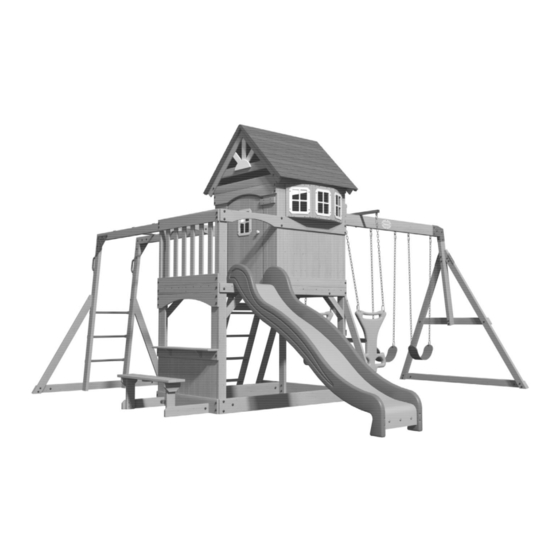
MONTPELIER
to register your set, or to order replacement parts please visit
SAVE THIS ASSEMBLY MANUAL FOR FUTURE REFERENCE IN THE EVENT THAT
Made in China | INS-30211D-MONTPELIER SWING SET-ENG 07/06/20
Model # 30211D
average 2 person assembly time
assembly time may vary based on skill level
For the most up to date assembly manual,
www.backyarddiscovery.com
YOU NEED TO ORDER REPLACEMENT PARTS.
Wooden Swing Set
Owner's Manual & Assembly Instructions
MANUFACTURED BY:
Backyard Discovery
3305 Airport Drive
Pittsburg, KS 66762
800-856-4445
Advertisement

Related Manuals for Backyard Discovery MONTPELIER


Summary of Contents for Backyard Discovery MONTPELIER
- Page 1 For the most up to date assembly manual, to register your set, or to order replacement parts please visit www.backyarddiscovery.com SAVE THIS ASSEMBLY MANUAL FOR FUTURE REFERENCE IN THE EVENT THAT YOU NEED TO ORDER REPLACEMENT PARTS. Made in China | INS-30211D-MONTPELIER SWING SET-ENG 07/06/20...
- Page 2 INSTALLATION SERVICES AVAILABLE! Need a helping hand? Let our team of professionals handle the installation for you! *Installation services are only available to U.S. customers. With Go Configure, we bring you 18 years of experience right to your doorstep. We service a wide array of indoor and outdoor recreation products that most consumers don’t have the time or ability to deliver &...
- Page 3 Owner’s Manual Please Read This Before Starting Assembly MISSING A PART? CALL US BEFORE GOING BACK TO THE STORE Th e store where you made your purchase does not stock parts for this item. If you have assembly questions or you are missing or have damaged parts, please call 1-800-856-4445 you can also visit www.backyarddiscovery.com...
- Page 4 Botanical, Adventure Playsets, and Leisure Time Products. Backyard Discovery warrants that this product is free from defect in materials and workmanship for a period of one (1) year from the original date of purchase. Th is one (1) year warranty covers all parts including wood, hardware, and accessories. All wood carries a fi ve (5) year pro-rated warranty against rot and decay. Refer to the schedule below for charges associated with replacement of parts under this Limited Warranty.
- Page 5 Owner’s Manual Operating Instructions and Safety Warnings WARNING: BURN HAZARD • Pay special attention to plastic and metal surfaces as they may be hot enough to cause burns. • Always check the temperature of the product before NOTE: letting your children play on it. •...
- Page 6 Owner’s Manual Please Read This Before Starting Assembly Positioning Your Playcenter Suggested Playground Surfacing • Th e playcenter is designed to be installed on a level • Do not install home playground equipment over surface by an adult with an adult helper. Place concrete, asphalt, packed earth, grass, carpet, or any in a fl at area of your yard to minimize ground other hard surface.
- Page 7 Owner’s Manual Please Read This Before Starting Assembly APPENDIX A The following information is from the United States X3.1.3.2 Do not install loose-fi ll surfacing over hard surfaces such as concrete or asphalt. Consumer Product Safety Commission’s Information X3.1.4 Poured-In-Place Surfaces or Pre-Manufactured Sheet for playground surfacing material;...
- Page 8 • Check all moving parts including swing seats, Backyard Discovery assumes no responsibility or ropes, cables, and chains for wear, rust, or other liability for any charge incurred by the Customer for deterioration.
- Page 9 About Our Wood Backyard Discovery uses 100% Cedar (C. Lanceolata) wood. Although we take great care in selecting the best quality lumber available, wood is still a product of nature and susceptible to weathering which can change the appearance of your set.
- Page 10 Owner’s Manual Assembly Tips Protrusion Hazard Incorrect Correct If you see exposed threads and your bolt protrudes beyond the T-Nut you may have over tightened the bolt or used incorrect hardware. If you’ve overtightened, remove the bolt and add washers to eliminate the protrusion.
- Page 11 Owner’s Manual Assembly Tips ASSEMBLY TIP: Keep an eye out for these boxes which will contain helpful pictures and information making the assembly process as quick and painless as possible. Sorting Wood When removing the wood from the boxes we recommend arranging them by part number before you begin assembly.
- Page 12 Owner's Manual Tools Required for Installation...
- Page 13 Owner's Manual Basic Setup Dimensions & Assembly Notes Place the set on level ground, not less than 6'-7" [2 m] from any structure or obstruction such as a fence, garage, house, overhanging branches, laundry lines, or electrical wires. • While assembling unit, take time before and after each phase to make sure fort is level. If fort is not level, assembly will be difficult and improper assembly may result.
- Page 14 Parts Identification Owner's Manual Wood Components (Not to Scale) UPRIGHT - W2A03132 1 3/8"x3 3/8"x89 1/2" (36x86x2274) (x1) UPRIGHT - W4L14532 1 3/8"x3 3/8"x73 1/8" (36x86x1856) (x1) UPRIGHT - W4L14533 1 3/8"x3 3/8"x89 1/2" (36x86x2274) (x1) CLUB HOUSE LEG - W4L14534 1 3/8"x3 3/8"x43 1/8"...
- Page 15 Parts Identification Owner's Manual Wood Components (Not to Scale) MONKEY BAR BRACE - W4L14544 1"x3 3/8"x51 1/2" (24x86x1308 mm) (x2) MONKEY BAR GROUND BOARD - W4L14545 1"x3 3/8"x70 3/8" (24x86x1786) (x1) ANGLE BRACE - W4L14549 15/16"x3 3/8"x47" (24x86x1194) (x2) BENCH GROUND BOARD - W4L14546 1"x3 3/8"x18 1/8"...
- Page 16 Parts Identification Owner's Manual Wood Components (Not to Scale) GROUND BOARD - W4L14557 5/8"x5 1/4"x64 3/4" (16x134x1644) (x2) GROUND BOARD - W4L14558 5/8"x5 1/4"x40 3/8" (16x134x1024) (x1) FLOOR SUPPORT - W4L14559 (x1) 5/8"x5 1/4"x40 3/8" (16x134x1024) GROUND BOARD - W4L14560 5/8"x5 1/4"x78 1/4"...
- Page 17 Parts Identification Owner's Manual Wood Components (Not to Scale) DOOR BOARD - W4L14569 (x1) 5/8"x4 3/8"x35" (16x110x890) DOOR BOARD - W4L14570 5/8"x4 3/8"x35" (16x110x890) (x1) FLOOR SUPPORT - W4L14571 5/8"x3 3/8"x64 3/4" (16x86x1644) (x1) FLOOR SUPPORT - W4L14572 5/8"x3 3/8"x40 3/8" (16x86x1024) (x2) FLOOR SUPPORT - W4L14573 5/8"x3 3/8"x40 3/8"...
- Page 18 Parts Identification Owner's Manual Wood Components (Not to Scale) WALL BOARD - W4L14583 5/8"x3 3/8"x22" (16x86x558) (x9) WALL BOARD - W4L14584 5/8"x3"x36 1/2" (16x76x926) (x1) WALL RAIL - W4L14585 5/8"x3 3/8"x8 1/2" (16x86x216) (x2) WALL RAIL - W4L14586 5/8"x3 3/8"x40 3/8" (16x86x1024) (x2) WALL RAIL - W4L14587 (x1)
- Page 19 Parts Identification Owner's Manual Wood Components (Not to Scale) FLOOR SUPPORT - W4L14598 5/8"x3 3/8"x64 3/4" (16x86x1644) (x1) GABLE BOARD - W4L14599 5/8"x3 3/8"x31 1/2" (16x86x800) (x2) WALL BOARD - W4L14600 5/8"x3"x36 1/2" (16x76x926) (x1) FILLER BOARD - W4L14617 5/8"x1 3/4"x33 1/2" (16x45x851) (x1) M102 SLIDE BRACE - W100544...
- Page 20 Parts Identification Owner's Manual Wood Components (Not to Scale) SB74 SWING BEAM EXTENDED - W4L06925 2"x5 1/4"x89 1/2" (50x134x2274) (x1) SWING BEAM SUPPORT - W4L14615 2"x3 3/8"x50 3/8" (50x86x1280) (x1) WALL BOARD - W4L14616 5/8"x4"x34 5/8" (16x102x880) (x2) FLOOR PANEL - W2A03131 1 1/4"x17"x40 5/16"...
- Page 21 Owner's Manual Parts Identification Hardware Components H100114 TORX WRENCH (x2) T-30 A100042 H100147 TORX BIT TORX BIT (x2) (x2) T-40 T-30 A100041 TORX WRENCH (x2) T-40 H100032 BOLT WH (x4) 5/16x5 3/4 H100097 SWING HANGER (x4) 5/16x6 H100074 T-NUT H100070 SCREW PWH (x7) 5/16...
-
Page 22: Table Of Contents
Owner's Manual Parts Identification Hardware Components H100472 BOLT HEX BLK H100415 BOLT WH BLK (x9) 5/16x2 3/4 (x2) 5/16x3 3/4 H100416 BOLT WH BLK (x2) 5/16x3 H100193 NUT BARREL WH BLK (x3) 5/16x1-1/2 H100194 BOLT WH BLK H100396 BOLT WH BLK (x3) 5/16x2 1/2 (x9) - Page 23 Owner's Manual Parts Identification Hardware Components H100405 H100473 WASHER LOCK INT BLK WASHER LOCK EXT BLK (x2) (x17) 8x15 6x15 H100477 WASHER SPLIT BLK H100198 WASHER LOCK EXT BLK (x4) 5/16 (x110) 8x19 H100474 WASHER FLAT BLK H100199 WASHER LOCK EXT BLK (x2) 9x18 (x60)
- Page 24 Owner's Manual Parts Identification Accessory Components (Not to Scale) A100055 SLIDE RAIL 8' GREEN LEFT (x1) A100054 SLIDE RAIL 8' GREEN RIGHT (x1) A100356 SLIDE BED 8' LIGHT GREEN (x1) SWING BEAM SWING BEAM A100326 A100325 EXTENSION (x1) EXTENSION (x1) BRACKET-RIGHT BRACKET-LEFT A100014...
- Page 25 Owner's Manual Parts Identification Accessory Components (Not to Scale) A100069 QUICK LINK A100025 (x8) GLIDER SEAT DARK GREEN (x1) A6P00054 A100021 SWING SEAT GREEN 22" GLIDER ARM LIGHT GREEN (x2) (x2) A100065 GLIDER SUPPORT BYD GREEN (x2) TUBING CAP GLIDER A100067 A100066 GLIDER...
- Page 26 Owner's Manual Parts Identification Accessory Components (Not to Scale) A100178 AUGER GROUND STAKE (x8) A4M00624 HINGE (DOOR, SPRING LOADED) (x2)
- Page 27 SWING BEAM STEP 1 ASSEMBLY SWING BEAM SWING BEAM A100326 A100325 EXTENSION EXTENSION (x1) (x1) BRACKET-RIGHT BRACKET-LEFT SB74 SWING BEAM EXTENDED - W4L06925 2"x5 1/4"x89 1/2" (50x134x2274) (x1) A100140 L BRACKET (x2) 66x66x127 H100472 BOLT HEX BLK H100478 WASHER FLAT BLK H100479 NUT LOCK BLK (x2)
- Page 28 SWING BEAM STEP 2 ASSEMBLY SWING BEAM SUPPORT - W4L14615 END SUPPORT - W4L14538 2"x3 3/8"x50 3/8" (50x86x1280) 1 1/2"x3 1/2"x46" (36x86x1168) (x1) (x1) A4M01169 GROUND BOARD - W4L14552 ANGLE BRACE - W4L14540 A-FRAME BRACKET (x1) (x1) 1"x3 3/8"x79 1/2" (24x86x2018) 1 3/8"x3 3/8"x81"...
-
Page 29: 5/16X1-1/2
SWING BEAM STEP 3 ASSEMBLY (x1) SWING BEAM END (x1) SWING BEAM SUBASSEMBLY SUBASSEMBLY H100194 BOLT WH BLK H100192 NUT BARREL WH BLK H100378 BOLT WH BLK H100193 NUT BARREL WH BLK (x1) (x2) 5/16x2 1/2 (x2) 5/16x7/8 5/16x1 3/4 (x1) 5/16x1-1/2 (x2) -
Page 30: Lag Screw Wh Blk
SWING BEAM STEP 4 ASSEMBLY A100066 A100065 A100067 GLIDER BUSHING BYD GREEN GLIDER SUPPORT BYD GREEN TUBING CAP GLIDER SUPPORT (x4) (x2) (x4) H100032 H100097 BOLT WH SWING HANGER (x2) 5/16x5 3/4 (x4) 5/16x6 H100028 LAG SCREW WH H100105 WASHER FLAT H100110 NUT LOCK (x2) - Page 31 SWING BEAM STEP 5 ASSEMBLY H100099 SWING HANGER (x4) 5/16x9 1/2 H100103 WASHER SAFETY H100105 WASHER FLAT H100110 NUT LOCK (x4) (x4) (x4) 17x30 8x27 5/16 (x4) NUT - 5/16" (x4) WASHER - 8x27 (x4) WASHER - 17x30 (x4) SWING HANGER - 9 1/2"...
- Page 32 STEP 1 GLIDER ASSEMBLY A100015 CHAIN GREEN 38.5" (x4) A100069 QUICK LINK (x4) A100025 GLIDER SEAT DARK GREEN A100021 (x1) GLIDER ARM LIGHT GREEN (x2) H100032 BOLT WH H100105 WASHER FLAT H100110 NUT LOCK (x2) (x2) (x2) 5/16x5 3/4 8x27 5/16 TIGHTEN QUICK...
- Page 33 STEP 1 SLIDE ASSEMBLY SLIDE BRACE - W100544 5/8"x3 3/8"x17 1/4" (16x86x438) (x1) A100356 SLIDE BED 8' LIGHT GREEN (x1) H100115 BOLT WH H100074 T-NUT (x3) (x3) 5/16x1/2 5/16 PLACE 'M77' SLIDE BRACE BOARD 1/4" FROM THE BOTTOM EDGE OF THE SLIDE BED. USING THE BOARD AS A TEMPLATE, MARK WHERE THE PILOT HOLES WILL BE DRILLED.
- Page 34 STEP 2 SLIDE ASSEMBLY A100054 SLIDE RAIL 8' GREEN RIGHT (x1) CENTER SLIDE BRACE - W4L08749 (x2) 5/8"x3 3/8"x17 1/4" (16x86x438) A100055 SLIDE RAIL 8' GREEN LEFT (x1) H100090 SCREW PFH (x24) 8x2 1/2" NOTE: USING A 1/8" DRILL BIT, DRILL PILOT HOLES IN EACH INDENTATION ALONG EACH SIDE RAIL. THERE SHOULD BE 12 INDENTIONS ON EACH RAIL.
- Page 35 MONKEY BAR STEP 1 ASSEMBLY MONKEY BAR RAIL - W4L06929 A100294 A100053 TRIANGLE PLATE 100° 5 HOLE L BRACKET 54x67 - GRN 1 3/8"x3 3/8"x60 5/8" (36x86x1539) (x1) (x1) (x1) H100457 H100407 H100379 T-NUT BLK H100478 H100479 BOLT WH BLK BOLT WH BLK WASHER FLAT BLK NUT LOCK BLK...
- Page 36 MONKEY BAR STEP 2 ASSEMBLY MONKEY BAR RAIL - W4L06929 A100294 A100053 TRIANGLE PLATE 100° 5 HOLE L BRACKET 54x67 - GRN 1 3/8"x3 3/8"x60 5/8" (36x86x1539) (x1) (x1) (x1) H100457 H100407 H100379 T-NUT BLK H100478 H100479 BOLT WH BLK BOLT WH BLK WASHER FLAT BLK NUT LOCK BLK...
- Page 37 MONKEY BAR STEP 3 ASSEMBLY MONKEY BAR UPRIGHT - W4L14536 A100028 HAND GRIP GREEN PLASTIC (x1) 1 3/8"x3 3/8"x71 3/8" (36x86x1812) (x1) H100407 BOLT WH BLK H100403 LAG SCREW WH BLK H100405 WASHER LOCK EXT BLK H100379 T-NUT BLK (x2) (x2) (x2) (x2)
- Page 38 MONKEY BAR STEP 4 ASSEMBLY MONKEY BAR UPRIGHT - W4L14536 A100028 HAND GRIP GREEN PLASTIC (x1) 1 3/8"x3 3/8"x71 3/8" (36x86x1812) (x1) H100407 BOLT WH BLK H100403 LAG SCREW WH BLK H100405 WASHER LOCK EXT BLK H100379 T-NUT BLK (x2) (x2) (x2) (x2)
-
Page 39: 1/4X1 1/2
MONKEY BAR STEP 5 ASSEMBLY A100045 H100403 LAG SCREW WH BLK METAL RUNG 559 GREEN (x6) (x12) 1/4x1 1/2 (x3) METAL RUNG 559 GREEN (x12) LAG SCREW - 1 1/2" (x3) METAL RUNG 559 GREEN... -
Page 40: Bolt Wh Blk
MONKEY BAR STEP 6 ASSEMBLY MONKEY BAR GROUND BOARD - W4L14545 MONKEY BAR BRACE - W4L14544 1"x3 3/8"x70 3/8" (24x86x1786) 1"x3 3/8"x51 1/2" (24x86x1308 mm) (x1) (x2) H100472 BOLT HEX BLK H100458 LAG SCREW WH BLK H100407 BOLT WH BLK H100192 NUT BARREL WH BLK H100379... - Page 41 LADDER STEP 1 ASSEMBLY LEFT UPRIGHT - W4L14550 LADDER RUNG - W4L14554 1"x3 3/8"x50 3/4" (24x86x1290) 1"x3 3/8"x17 1/8" (24x86x434) (x1) (x4) H100111 SCREW PFH (x8) (x8) SCREW - 2" (x1) LEFT UPRIGHT (x4) LADDER RUNG...
- Page 42 LADDER STEP 2 ASSEMBLY H100111 SCREW PFH RIGHT UPRIGHT - W4L14551 (x8) 1"x3 3/8"x50 3/4" (24x86x1290) (x1) (x8) SCREW - 2" (x1) RIGHT UPRIGHT...
- Page 43 LADDER STEP 3 ASSEMBLY M102 REAR SUPPORT - W4L14601 H100086 SCREW PFH 5/8"x3 3/8"x18 1/4" (16x86x462) (x4) (x1) 8x1 1/2 M102 (x1) REAR SUPPORT (x4) SCREW - 1 1/2"...
- Page 44 LADDER STEP 4 ASSEMBLY H100089 SCREW PFH ATTACHMENT BOARD - W4L14553 (x4) 8x1 3/4 1"x3 3/8"x18 1/4" (24x86x462) (x1) (x??) ATTACHMENT BOARD FLUSH TO TOP. (x4) SCREW - 1 3/4"...
- Page 45 BAY WINDOW STEP 1 ASSEMBLY BAY WINDOW BOARD - W4L14606 BAY WINDOW HEADER - W4L14568 BAY WINDOW BOARD - W4L14605 5/8"x2 3/8"x6 1/4" (16x60x158) 5/8"x4 3/8"x30 1/2" (16x112x774) 5/8"x2 3/8"x13 1/8" (16x60x332) (x2) (x2) (x2) H100088 SCREW PFH (x8) 8x1 1/8 NOTE: TO PREVENT SPLITTING, LOCATE, MARK HOLE LOCATIONS, &...
- Page 46 BAY WINDOW STEP 2 ASSEMBLY BAY WINDOW BOARD - W4L14605 BAY WINDOW BOARD - W4L14606 H100088 H100085 SCREW PFH SCREW PFH 5/8"x2 3/8"x13 1/8" (16x60x332) (x2) 5/8"x2 3/8"x6 1/4" (16x60x158) (x2) (x6) (x2) 8x1 1/8 (x1) BAY WINDOW BOARD (x1) BAY WINDOW BOARD (x2) SCREW - 1"...
- Page 47 BAY WINDOW STEP 3 ASSEMBLY BAY WINDOW BOARD - W4L14605 BAY WINDOW BOARD - W4L14606 H100088 SCREW PFH H100085 SCREW PFH 5/8"x2 3/8"x13 1/8" (16x60x332) (x2) (x6) 5/8"x2 3/8"x6 1/4" (16x60x158) 8x1 1/8 (x2) (x2) (x1) BAY WINDOW BOARD (x2) SCREW - 1"...
- Page 48 BAY WINDOW STEP 4 ASSEMBLY H100070 SCREW PWH (x12) 8x3/4 A100014 PLASTIC WINDOW WHITE (x3) (x3) PLASTIC WINDOW WHITE (x12) SCREW - 8x3/4" 1 5/16 in [33 mm]...
- Page 49 DOOR ASSEMBLY STEP 1 DOOR BOARD - W4L14569 DOOR BOARD - W4L14570 DOOR BOARD - W4L14594 5/8"x4 3/8"x35" (16x110x890) 5/8"x4 3/8"x35" (16x110x890) (x1) 5/8"x3 3/8"x21 1/4" (16x86x540) (x1) (x2) DOOR BOARD - W4L14593 DOOR CLEAT - W4L14609 DOOR BOARD - W4L14595 5/8"x3 3/8"x35 3/4"...
- Page 50 DOOR ASSEMBLY STEP 2 H100070 SCREW PWH (x4) 8x3/4 A100014 PLASTIC WINDOW WHITE (x1) (x1) PLASTIC WINDOW WHITE (x4) SCREW - 8x3/4" 7 in [174 mm]...
- Page 51 STEP 3 DOOR ASSEMBLY A4M00624 A6P00122 HINGE (DOOR, SPRING LOADED) KNOB - LT BROWN (x2) (x1) H100624 SCREW PFH BLK H100088 SCREW PFH (x6) (x1) 6x5/8 8x1 1/8 (x6) SCREW - 5/8" (x1) HINGE (DOOR, SPRING LOADED) (x1) HINGE (DOOR, SPRING LOADED) (x1) SCREW - 1 1/8"...
- Page 52 STEP 1 BENCH ASSEMBLY BENCH GROUND BOARD - W4L14546 A100061 L BRACKET GREEN 32x51 1"x3 3/8"x18 1/8" (24x86x460) (x2) (x2) H100663 BOLT WH BLK H100199 WASHER LOCK EXT BLK H100469 NUT BARREL WH BLK (x2) (x2) (x2) 5/16x3/4 12x19 5/16x5/8 NOTE: ASSEMBLE A LEFT AND A RIGHT BENCH (x2)
- Page 53 BENCH ASSEMBLY STEP 2 BENCH UPRIGHT - W4L14547 H100089 SCREW PFH 1"x3 3/8"x11 3/4" (24x86x300) (x8) (x2) 8x1 3/4 (x1) BENCH UPRIGHT (x8) SCREW - 1 3/4" RIGHT (x1) BENCH UPRIGHT LEFT 1 3/16 in [30 mm]...
- Page 54 BENCH ASSEMBLY STEP 3 BENCH SEAT SUPPORT - W4L14548 H100089 SCREW PFH 1"x3 3/8"x6 1/2" (24x86x166) (x2) (x8) 8x1 3/4 (x1) BENCH SEAT SUPPORT (x8) SCREW - 1 3/4" LEFT (x1) BENCH SEAT SUPPORT RIGHT...
- Page 55 BENCH ASSEMBLY STEP 4 BENCH SEAT - W4L14555 BENCH CLEAT - W4L14607 5/8"x2 3/8"x5 1/8" (16x60x130) 1"x3 3/8"x35 3/8" (24x86x900) (x1) (x2) H100089 H100088 SCREW PFH SCREW PFH (x8) (x4) 8x1 3/4 8x1 1/8 (x8) SCREW - 1 3/4" CENTER BENCH SEAT BOARDS ON BENCH SUPPORTS, AS SHOWN.
- Page 56 FORT ASSEMBLY STEP 1 SAFETY BOARD - W4L14602 UPRIGHT - W2A03132 5/8"x2 3/8"x40 3/8" (16x60x1024) (x1) SWING BEAM MOUNT - W4L14542 1 3/8"x3 3/8"x89 1/2" (36x86x2274) (x1) (x1) 1"x5 1/4"x40 3/8" (24x134x1024) UPRIGHT - W4L14533 FLOOR SUPPORT - W4L14578 WALL RAIL - W4L14566 (x1) 1 3/8"x3 3/8"x89 1/2"...
- Page 57 STEP 2 FORT ASSEMBLY UPRIGHT - W4L14532 FLOOR SUPPORT - W4L14559 GROUND BOARD - W4L14558 (x1) 1 3/8"x3 3/8"x73 1/8" (36x86x1856) (x1) 5/8"x5 1/4"x40 3/8" (16x134x1024) 5/8"x5 1/4"x40 3/8" (16x134x1024) (x1) UPRIGHT - W4L14535 1 3/8"x3 3/8"x73 1/8" (36x86x1856) FLOOR SUPPORT - W4L14572 (x1) FLOOR SUPPORT - W4L14573 5/8"x3 3/8"x40 3/8"...
- Page 58 STEP 3 FORT ASSEMBLY FLOOR SUPPORT - W4L14571 WALL RAIL - W4L14564 (x1) 5/8"x3 3/8"x64 3/4" (16x86x1644) 5/8"x4 3/8"x64 3/4" (16x112x1644) (x1) FLOOR SUPPORT - W4L14598 WALL RAIL - W4L14565 5/8"x3 3/8"x64 3/4" (16x86x1644) (x1) 5/8"x4 3/8"x64 3/4" (16x112x1644) (x1) GROUND BOARD - W4L14557 5/8"x5 1/4"x64 3/4"...
- Page 59 STEP 4 FORT ASSEMBLY H100407 BOLT WH BLK H100198 H100379 T-NUT BLK WASHER LOCK EXT BLK (x6) 5/16x1 1/2 (x6) DECK BRACE - W4L14541 (x6) 5/16 8x19 (x6) 1"x2 3/8"x15 3/4" (24x60x400) H100487 LAG SCREW WH BLK H100405 WASHER LOCK EXT BLK (x6) (x6) 1/4x2...
- Page 60 STEP 5 FORT ASSEMBLY WALL BOARD - W4L14579 WALL BOARD - W4L14580 (x2) 5/8"x3 3/8"x40" (16x86x1016) 5/8"x3 3/8"x20" (16x86x508) (x9) A100314 "A" REVISION TAG (x1) H100088 SCREW PFH H100202 SCREW PWH BLK (x46) (x2) 8x1 1/8 8x5/8 (x2) (x46) SCREW - 1 1/8" (x9) M10 BOARDS ARE FLUSHED TO TOP...
- Page 61 STEP 6 FORT ASSEMBLY H100087 SCREW PFH COUNTER TOP - W4L14561 TABLE SUPPORT - W4L14543 (x7) 8x1 1/4 (x1) 5/8"x5 1/4"x40 3/8" (16x134x1024) (x2) 1"x2"x4" (24x51x102) (x5) SCREW - 1-1/4" (x2) SCREW - 1-1/4" (x1) (x2)
- Page 62 STEP 7 FORT ASSEMBLY FLOOR SUPPORT - W4L14612 (x2) 1"x1"x59 7/8" (24x24x1522) H100086 SCREW PFH (x28) 8x1 1/2 FLOOR SUPPORT - W4L14613 FLOOR SUPPORT - W4L14614 1"x1"x37 1/2" (24x24x952) 1"x1"x33 1/2" (24x24x852) (x1) (x1) (x28) SCREW - 1 1/2" NOTE HOLE LOCATION IN 'S2' &...
- Page 63 STEP 8 FORT ASSEMBLY H100090 SCREW PFH JOIST - W4L14556 (x4) 8x2 1/2" 1"x2 3/8"x64 3/4" (24x60x1644) (x1) (x1) (x4) SCREW - 2 1/2"...
- Page 64 STEP 9 FORT ASSEMBLY FLOOR BOARD - W4L14574 (x2) 5/8"x3 3/8"x40 3/8" (16x86x1024) FLOOR BOARD - W4L14575 H100086 SCREW PFH 5/8"x3 3/8"x40 3/8" (16x86x1024) (x1) (x91) 8x1 1/2 FLOOR PANEL - W2A03131 1 1/4"x17"x40 5/16" (32x432x1024) FLOOR BOARD - W4L14576 (x3) (x1) 5/8"x3 3/8"x37 1/2"...
- Page 65 STEP 1 0 FORT ASSEMBLY CLUB HOUSE LEG - W4L14534 H100407 BOLT WH BLK H100198 WASHER LOCK EXT BLK 1 3/8"x3 3/8"x43 1/8" (36x86x1094) (x1) (x4) 5/16x1 1/2 (x4) 8x19 CLUB HOUSE LEG - W4L14537 H100199 H100192 NUT BARREL WH BLK WASHER LOCK EXT BLK 1 3/8"x3 3/8"x43 1/8"...
- Page 66 STEP 1 1 FORT ASSEMBLY WALL RAIL - W4L14587 FLOOR SUPPORT - W4L14581 5/8"x3 3/8"x6 3/4" (16x86x173) 5/8"x3 3/8"x37 1/2" (16x86x951) (x1) (x1) A4M01046 WALL RAIL - W4L14585 L BRACKET 2.5x38x55x55 WALL RAIL - W4L14588 (x2) (x2) 5/8"x3 3/8"x8 1/2" (16x86x216) 5/8"x3 3/8"x4 3/4"...
- Page 67 STEP 1 2 FORT ASSEMBLY PICKET - W4L14603 H100088 SCREW PFH (x6) 5/8"x2 3/8"x22" (16x60x558) (x12) 8x1 1/8 (x12) SCREW - 1 1/8" 3 3/8 in [85 mm] SPACING 1 5/8 in [40 mm] (x6)
- Page 68 STEP 13 FORT ASSEMBLY H100457 BOLT WH BLK H100379 T-NUT BLK CLUB HOUSE WALL RAIL - W4L14567 (x2) 5/16x2 (x2) 5/16 5/8"x4 3/8"x40 3/8" (16x112x1024) (x1) WALL RAIL - W4L14591 5/8"x3 3/8"x37 1/2" (16x86x951) (x2) H100458 LAG SCREW WH BLK H100198 WASHER LOCK EXT BLK (x6)
- Page 69 FORT ASSEMBLY STEP 14 WALL BOARD - W4L14584 (x1) 5/8"x3"x36 1/2" (16x76x926) H100468 BOLT WH BLK H100199 H100088 SCREW PFH WASHER LOCK EXT BLK (x2) (x16) 5/16x1 (x2) 12x19 8x1 1/8 WALL BOARD - W4L14600 (x1) 5/8"x3"x36 1/2" (16x76x926) A4M01046 L BRACKET 2.5x38x55x55 (x2) WALL BOARD - W4L14616...
- Page 70 FORT ASSEMBLY STEP 15 WALL BOARD - W4L14589 WALL BOARD - W4L14596 5/8"x3 3/8"x40 5/8" (16x86x1032) 5/8"x3 3/8"x3 1/2" (16x86x88) (x2) (x8) H100088 SCREW PFH (x36) 8x1 1/8 WALL BOARD - W4L14590 WALL BOARD - W4L14562 5/8"x3 3/8"x16 1/4" (16x86x412) (x2) 5/8"x5 1/4"x16 1/4"...
- Page 71 FORT ASSEMBLY STEP 16 17 3/4 in 17 3/4 in [450 mm] [450 mm] WALL BOARD - W4L14592 WALL BOARD - W4L14582 H100088 SCREW PFH 5/8"x2 7/8"x38 7/8" (16x73x986) (x1) (x9) 5/8"x3 3/8"x38 7/8" (16x86x986) (x30) 8x1 1/8 (x30) SCREW - 1 1/8" (x9) (x1) 1 3/4 in...
- Page 72 FORT ASSEMBLY STEP 17 WALL BOARD - W4L14604 WALL BOARD - W4L14583 5/8"x2"x22" (16x50x558) H100088 SCREW PFH (x1) 5/8"x3 3/8"x22" (16x86x558) (x9) (x38) 8x1 1/8 (x38) SCREW - 1 1/8" 1 3/4 in [46 mm] (x1) (x9)
- Page 73 STEP 18 FORT ASSEMBLY H100070 SCREW PWH (x8) 8x3/4 A100014 PLASTIC WINDOW WHITE (x2) (x8) (x2) SCREW - 8x3/4" PLASTIC WINDOW WHITE...
- Page 74 STEP 19 FORT ASSEMBLY H100088 SCREW PFH WALL BOARD - W4L14610 (x4) 8x1 1/8 5/8"x1 3/8"x15 1/2" (16x34x395) (x2) (x4) SCREW - 1 1/8" (x1) (x1) 1 5/7 in [43 mm]...
- Page 75 STEP 20 FORT ASSEMBLY H100111 SCREW PFH (x6) MONTPELIER BAY WINDOW (x1) NOTE: FASTENERS MUST REMAIN VERTICAL TO AVOID PROTRUDING OUT OF THE SIDE OF 'L2' & 'M21' BOARDS. MONTPELIER BAY WINDOW (x6) SCREW - 2"...
- Page 76 FORT ASSEMBLY STEP 21 H100624 H100088 SCREW PFH SCREW PFH BLK DOOR STOP - W4L14608 (x4) (x6) 8x1 1/8 6x5/8 (x1) 5/8"x2 3/8"x8 3/4" (16x60x222) DOOR ASSEMBLY (x1) (x1) 1 1/4 in [33 mm] 1 3/8 in [35 mm] SPACING (x4) SCREW - 1 1/8"...
- Page 77 STEP 22 FORT ASSEMBLY H100403 LAG SCREW WH BLK (x2) 1/4x1 1/2 H100405 WASHER LOCK EXT BLK H100398 T-NUT BLK (x4) (x2) 6x15 A100028 HAND GRIP GREEN PLASTIC (x2) H101026 BOLT WH BLK (x2) 1/4x1-3/4 (x2) (x2) BOLT - 1-3/4" WASHER - 6x15 (x2) T-NUT - 1/4"...
- Page 78 STEP 23 FORT ASSEMBLY WALL RAIL - W4L14586 5/8"x3 3/8"x40 3/8" (16x86x1024) (x2) H100194 BOLT WH BLK H100458 LAG SCREW WH BLK H100198 WASHER LOCK EXT BLK (x2) (x2) (x4) 5/16x2 1/2 5/16x2 8x19 ROOF RAFTER - W4L14597 5/8"x3 3/8"x34 1/4" (16x86x871) (x4) GABLE BOARD - W4L14599 H100088...
- Page 79 STEP 24 FORT ASSEMBLY H100088 SCREW PFH H100070 SCREW PWH (x4) 8x1 1/8 (x8) 8x3/4 A100361 PLASTIC SUNBURST (x2) (x8) SCREW - 8x3/4" (x1) PLASTIC SUNBURST (x4) SCREW - 1 1/8" (x1) PLASTIC SUNBURST...
- Page 80 STEP 25 FORT ASSEMBLY H100086 SCREW PFH (x8) 8x1 1/2 ROOF PANEL - W2A03134 (x2) 1 1/16"x16 1/8"x42 5/8" (35x410x1083) (x1) (x4) SCREW - 1 1/2" (BOTH SIDES) NOTE MOUNTING LOCATIONS.
- Page 81 STEP 26 FORT ASSEMBLY H100086 SCREW PFH (x8) 8x1 1/2 ROOF PANEL - W2A03133 1 1/16"x19 5/16"x42 5/8" (35x491x1083) (x2) (x4) SCREW - 1 1/2" (BOTH SIDES) (x1) (x1) MOUNTING LOCATIONS.
- Page 82 STEP 27 FORT ASSEMBLY H100396 H100199 H100469 BOLT WH BLK WASHER LOCK EXT BLK NUT BARREL WH BLK (x2) 5/16x1/2 (x2) 12x19 (x2) 5/16x5/8 BENCH ASSEMBLY (x1) (x2) (x2) NUT BARREL - 5/8 WASHER - 12x19 (x2) BOLT - 1/2" (x2) L BRACKET GREEN 32x51 BENCH ASSEMBLY...
- Page 83 STEP 28 FORT ASSEMBLY WALL RAIL - W4L14611 H100205 BOLT WH BLK H100198 WASHER LOCK EXT BLK H100379 T-NUT BLK (x2) 1"x4 3/8"x40 3/4" (24x112x1034) (x2) 5/16x2-1/4 (x2) 8x19 (x2) 5/16 FILLER BOARD - W4L14617 H100089 SCREW PFH 5/8"x1 3/4"x33 1/2" (16x45x851) (x1) (x2) 8x1 3/4...
- Page 84 STEP 29 FORT ASSEMBLY H100407 BOLT WH BLK H100198 WASHER LOCK EXT BLK (x2) 5/16x1 1/2 (x2) 8x19 LADDER ASSEMBLY (x1) (x2) (x2) BOLT - 1 1/2" WASHER - 8x19 LADDER ASSEMBLY...
- Page 85 STEP 30 FORT ASSEMBLY H100396 H100199 H100469 BOLT WH BLK WASHER LOCK EXT BLK NUT BARREL WH BLK (x2) 5/16x1/2 (x2) 12x19 (x2) 5/16x5/8 MONKEY BAR ASSEMBLY (x1) (x2) (x2) WASHER - 12x19 NUT BARREL - 5/8 (x2) BOLT - 1/2" MONKEY BAR ASSEMBLY...
- Page 86 STEP 31 FORT ASSEMBLY A100164 BYD ID TAG (LARGE) AGES 3-10 (x1) SWING BEAM ASSEMBLY (x1) H100472 BOLT HEX BLK H100477 WASHER SPLIT BLK H100478 WASHER FLAT BLK H100128 SCREW PWH H100379 T-NUT BLK (x4) 5/16x2 3/4 (x4) 5/16 (x4) 8x27 (x4) 8x5/8...
- Page 87 STEP 32 FORT ASSEMBLY A100068 CHAIN GREEN 51.25" (x4) A100069 A6P00054 QUICK LINK SWING SEAT GREEN 22" GLIDER ASSEMBLY (x4) (x1) (x2) TIGHTEN QUICK LINK (x4) CHAIN GREEN 51.25" INSERT CHAIN INTO QUICK LINK GLIDER ASSEMBLY (x4) QUICK LINK (x2) SWING SEAT GREEN 22"...
- Page 88 STEP 33 FORT ASSEMBLY H100115 BOLT WH H100074 T-NUT (x3) (x3) 5/16x1/2 5/16 SLIDE ASSEMBLY (x1) 7 5/8 in [194 mm] 1 1/8 in [30 mm] 1 1/8 in [30 mm] 1 in 4 1/4 in [25 mm] [108 mm] 2 1/4 in 2 1/4 in [58 mm]...
- Page 89 STEP 34 FORT ASSEMBLY H100468 BOLT WH BLK (x4) 5/16x1 A100178 AUGER GROUND STAKE (x8) H100199 WASHER LOCK EXT BLK H100469 NUT BARREL WH BLK (x8) 12x19 (x8) 5/16x5/8 H100663 BOLT WH BLK (x4) 5/16x3/4 NOTE: NOTE: GROUND STAKE LOCATIONS TWIST GROUND STAKE INTO REPEAT ON OPPOSITE SIDE.
Need help?
Do you have a question about the MONTPELIER and is the answer not in the manual?
Questions and answers