Advertisement
Quick Links
Basepoint Business Centre: Rivermead Drive,Westlea, Swindon SN5 7EX Phone: 0800-118-2476
J.P. Coenstraat 7, The Bridge, The Hague, 2595 WP, Netherlands Phone: 0800-567-8990
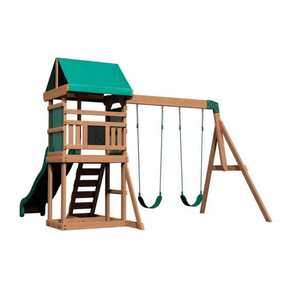
BUCKLEY HILL
Swing Set
Model # 2001046
The assembly manual must be retained
since it contains important information
WARNING
Adult Assembly Required.
Not suitable for children under 36 months due to small parts.
FOR DOMESTIC USE ONLY. INTENDED FOR OUTDOOR USE.
For the most up to date assembly manual, to register your set, or to order replacement parts
Para obtener instrucciones en español, visite www.backyarddiscovery.com
MANUFACTURED BY:
Backyard Discovery
3305 Airport Drive, Pittsburg, KS 66762
800-856-4445
Please visit www.backyarddiscovery.com
INS-2001046-A-BUCKLEY HILL-ENG 10-27-21
Made in China
Advertisement

Related Manuals for Backyard Discovery BUCKLEY HILL


Summary of Contents for Backyard Discovery BUCKLEY HILL
- Page 1 FOR DOMESTIC USE ONLY. INTENDED FOR OUTDOOR USE. Please visit www.backyarddiscovery.com For the most up to date assembly manual, to register your set, or to order replacement parts Para obtener instrucciones en español, visite www.backyarddiscovery.com Made in China INS-2001046-A-BUCKLEY HILL-ENG 10-27-21...
- Page 2 INSTALLATION SERVICES AVAILABLE! Need a helping hand? Let our team of professionals handle the installation for you! *Installation services are only available to U.S. customers. With Go Configure, we bring you 18 years of experience right to your doorstep. We service a wide array of indoor and outdoor recreation products that most consumers don’t have the time or ability to deliver &...
- Page 3 Owner’s Manual Please Read This Before Starting Assembly MISSING A PART? CALL US BEFORE GOING BACK TO THE STORE Th e store where you made your purchase does not stock parts for this item. If you have assembly questions or you are missing or have damaged parts, please call 1-800-856-4445 you can also visit www.backyarddiscovery.com...
- Page 4 All wood carries a five (5) year warranty against rot and decay from the original purchase date. Backyard Discovery Metal Play Structure Backyard Discovery warrants this metal play product to be free from defects in materials and workmanship for a period of five (5) years from the original date of purchase. General Warranty Information This warranty applies to the original owner and registrant and is non-transferable.
- Page 5 Owner’s Manual Operating Instructions and Safety Warnings WARNING: BURN HAZARD • Pay special attention to plastic and metal surfaces as they may be hot enough to cause burns. • Always check the temperature of the product before NOTE: letting your children play on it. •...
- Page 6 Owner’s Manual Please Read This Before Starting Assembly Positioning Your Playcenter Suggested Playground Surfacing • Th e playcenter is designed to be installed on a level • Do not install home playground equipment over surface by an adult with an adult helper. Place concrete, asphalt, packed earth, grass, carpet, or any in a fl at area of your yard to minimize ground other hard surface.
- Page 7 Owner’s Manual Please Read This Before Starting Assembly APPENDIX A The following information is from the United States X3.1.3.2 Do not install loose-fi ll surfacing over hard surfaces such as concrete or asphalt. Consumer Product Safety Commission’s Information X3.1.4 Poured-In-Place Surfaces or Pre-Manufactured Sheet for playground surfacing material;...
- Page 8 • Check all moving parts including swing seats, Backyard Discovery assumes no responsibility or ropes, cables, and chains for wear, rust, or other liability for any charge incurred by the Customer for deterioration.
- Page 9 About Our Wood Backyard Discovery uses 100% Cedar (C. Lanceolata) wood. Although we take great care in selecting the best quality lumber available, wood is still a product of nature and susceptible to weathering which can change the appearance of your set.
- Page 10 Owner’s Manual Assembly Tips Protrusion Hazard Incorrect Correct If you see exposed threads and your bolt protrudes beyond the T-Nut you may have over tightened the bolt or used incorrect hardware. If you’ve overtightened, remove the bolt and add washers to eliminate the protrusion.
- Page 11 Owner’s Manual Assembly Tips ASSEMBLY TIP: Keep an eye out for these boxes which will contain helpful pictures and information making the assembly process as quick and painless as possible. Sorting Wood When removing the wood from the boxes we recommend arranging them by part number before you begin assembly.
- Page 12 Tools Required for Installation Owner's Manual...
- Page 13 Basic Setup Dimensions & Assembly Notes Owner's Manual Place the set on level ground, not less than 6'-7" [2 m] from any structure or obstruction such as a fence, garage, house, overhanging branches, laundry lines, or electrical wires. • While assembling unit, take time before and after each phase to make sure fort is level. If fort is not level, assembly will be difficult and improper assembly may result.
- Page 14 Parts Identification Owner's Manual Wood Components (Not to Scale) RIGHT FRONT UPRIGHT - W4L15660 1 3/8"x3 3/8"x75" (36x86x1905) POST ASSEMBLY - W2A02839 1 7/16"x3 3/8"x75" (36x86x1905) LEFT BACK UPRIGHT - W4L13210 1 3/8"x3 3/8"x75" (36x86x1905) RIGHT BACK UPRIGHT - W4L13211 1 3/8"x3 3/8"x75"...
- Page 15 Parts Identification Owner's Manual Wood Components (Not to Scale) GROUND RAIL - W4L13209 SAFETY RAIL - W4L13299 5/8"x3 3/8"x36 5/8" (16x86x930) 1"x2 3/8"x36 5/8" (24x60x930) GROUND RAIL - W4L13296 5/8"x3 3/8"x21 3/8" (16x86x542) FLOOR BOARD - W4L13223 5/8"x4 3/8"x33 3/4" (16x112x856) SLIDE BRACE - W4L13297 5/8"x3 3/8"x14 1/4"...
- Page 16 Parts Identification Owner's Manual Hardware Components H100021 BOLT WH 5/16x4 1/2 H100017 BOLT WH H100029 LAG SCREW WH 5/16x3 1/4 5/16x3 H100013 H100028 BOLT WH LAG SCREW WH (11) 5/16x2 1/4 5/16x2 1/2 H100012 BOLT WH H100027 LAG SCREW WH (20) (22) 5/16x2...
- Page 17 Parts Identification Owner's Manual Hardware Components H100090 SCREW PFH H100047 H100095 BOLT HEX (22) WASHER SPLIT 8x2 1/2" 5/16x2 3/4 5/16 H100111 SCREW PFH (13) H100044 BOLT HEX 5/16x2 H100108 WASHER LOCK INT 8x15 H100089 SCREW PFH (11) 8x1 3/4 H100042 BOLT HEX 5/16x1 1/4...
- Page 18 Parts Identification Owner's Manual Accessory Components (Not to Scale) 90° L-BRACKET - A4M01110 A4M01046 L BRACKET HAND GRIP A100028 A100140 L BRACKET 2.5x38x55x55 GREEN PLASTIC 66x66x127 AUGER GROUND A100178 A6P00037 GREEN HC ROCK BYD ID TAG STAKE A100175 (MEDIUM) AGES 3-10 "A"...
- Page 19 Parts Identification Owner's Manual Accessory Components (Not to Scale) 6 FT SLIDE RAIL A6P00389 LEFT 6 FT SLIDE RAIL A6P00390 RIGHT A6P00391 6 FT SLIDE BED A6P00323 CHALK BOARD A6P00380 A6P00379 MESH PANEL ROOF TARP...
- Page 20 STEP 1 LADDER ASSEMBLY H100072 T-NUT H100063 BOLT PTH WASHER A6P00037 H100108 GREEN HC ROCK #2 (x8) LADDER RUNG - W4L13286 (x4) (x8) LOCK INT 1/4x3/4 (x4) 5/8"x4 3/8"x16 7/8" (16x112x430) 8x15 (x4) LADDER RUNG (x4) GREEN HC ROCK #2 (x8) (x8) WASHER - 8x15...
- Page 21 STEP 2 LADDER ASSEMBLY LEFT RUNG ASSEMBLY (x2) H100086 SCREW PFH (x20) LADDER RUNG - W4L13285 8x1 1/2 5/8"x4 3/8"x16 7/8" (16x112x430) (x1) RIGHT RUNG ASSEMBLY (x2) UPRIGHT - W4L13283 1 7/16"x2 3/8"x43 3/4" (36x60x1111) (x1) UPRIGHT - W4L13284 1 7/16"x2 3/8"x43 3/4" (36x60x1111) (x1) (x1) TIP:...
- Page 22 STEP 1 SLIDE ASSEMBLY SLIDE BRACE - W4L13297 5/8"x3 3/8"x14 1/4" (16x86x362) A6P00391 6 FT SLIDE BED H100115 BOLT WH H100074 T-NUT 5/16x1/2 5/16 NOTE TAKE NOTE OF SLIDE BED SURFACE FINISH, THE DULL SIDE WILL BE TOWARDS THE GROUND. PLACE SLIDE BRACE CENTERED ON THE BOTTOM (DULL SIDE) AND 1/2"...
- Page 23 STEP 2 SLIDE ASSEMBLY A6P00390 6 FT SLIDE RAIL RIGHT SLIDE BRACE - W4L13298 5/8"x3 3/8"x14 1/4" (16x86x362) A6P00389 6 FT SLIDE RAIL LEFT H100090 SCREW PFH (16) 8x2 1/2" NOTE: USING A 1/8" DRILL BIT, DRILL PILOT HOLES IN EACH INDENTATION ALONG EACH SIDE RAIL. THERE SHOULD BE 8 INDENTIONS ON EACH RAIL.
- Page 24 STEP 1 SWING BEAM A100140 L BRACKET 66x66x127 SB74 SWING BEAM 2 POSITION - W4L13291 SWING BEAM SWING BEAM 2"x5 1/4"x68 3/4" (50x134x1745) BYD ID TAG A100326 A100325 A100175 EXTENSION EXTENSION (MEDIUM) AGES BRACKET-RIGHT BRACKET-LEFT 3-10 H100128 H100047 BOLT HEX SCREW PWH H100110 H100011...
- Page 25 STEP 2 SWING BEAM H100099 SWING HANGER H100110 NUT LOCK H100105 WASHER FLAT H100103 WASHER SAFETY 5/16x9 1/2 5/16 8x27 17x30 (x4) NUT - 5/16" (x4) WASHER - 8x27 (x4) WASHER - 17x30 (x4) SWING HANGER - 9 1/2"...
- Page 26 STEP 3 SWING BEAM ANGLE BRACE - W4L13293 1 3/8"x3 3/8"x72 7/8" (36x86x1850) END SUPPORT - W4L13294 SWING BEAM SUPPORT - W4L13292 1"x3 1/2"x39 1/2" (24x86x1000) 2"x3 3/8"x44 1/4" (50x86x1123) H100021 BOLT WH H100027 H100013 BOLT WH LAG SCREW WH H100005 NUT BARREL WH 5/16x4 1/2...
- Page 27 STEP 4 SWING BEAM SWING BEAM SUB ASSEMBLY (FROM STEP 2) H100011 BOLT WH H100005 NUT BARREL WH 5/16x1 3/4 5/16x7/8 'A' FRAME SUB ASSEMBLY (FROM STEP 3) (x2) BOLT - 1 3/4" (x2) NUT BARREL - 7/8"...
- Page 28 STEP 1 FORT ASSEMBLY FLOOR RAIL - W4L13295 GROUND RAIL - W4L13209 H100028 LAG SCREW WH 1"x3 3/8"x36 5/8" (24x86x930) 5/8"x3 3/8"x36 5/8" (16x86x930) 5/16x2 1/2 TOP RAIL - W4L13220 5/8"x2 3/8"x36 5/8" (16x60x930) H100027 LAG SCREW WH 5/16x2 RIGHT FRONT UPRIGHT - W4L15660 1 3/8"x3 3/8"x75"...
- Page 29 STEP 2 FORT ASSEMBLY LEFT BACK UPRIGHT - W4L13210 H100028 LAG SCREW WH 1 3/8"x3 3/8"x75" (36x86x1905) 5/16x2 1/2 RIGHT BACK UPRIGHT - W4L13211 H100027 LAG SCREW WH 1 3/8"x3 3/8"x75" (36x86x1905) 5/16x2 GROUND RAIL - W4L13215 FLOOR RAIL - W4L13212 5/8"x3 3/8"x36 5/8"...
- Page 30 STEP 3 FORT ASSEMBLY ANGLE GROUND RAIL - W4L13217 H100017 BOLT WH 5/8"x3 3/8"x65 5/8" (16x86x1666) H100074 T-NUT 5/16x3 1/4 5/16 SIDE RAIL - W4L13214 FLOOR RAIL - W4L13213 5/8"x2 3/8"x24 1/8" (16x60x612) 1"x3 3/8"x26" (24x86x660) H100012 BOLT WH 5/16x2 H100030 WASHER LOCK FLOOR SUPPORT - W4L13222...
- Page 31 STEP 4 FORT ASSEMBLY H100017 BOLT WH GROUND RAIL - W4L13216 FLOOR RAIL - W4L13213 H100074 T-NUT 5/16x3 1/4 5/8"x3 3/8"x25 3/8" (16x86x644) 1"x3 3/8"x26" (24x86x660) 5/16 FLOOR SUPPORT - W4L13222 H100012 BOLT WH 1"x3 3/8"x3 3/8" (24x86x86) 5/16x2 H100030 WASHER LOCK 8x19 (x1)
- Page 32 STEP 5 FORT ASSEMBLY H100090 SCREW PFH 8x2 1/2" FLOOR SUPPORT - W4L13289 FLOOR RAIL - W4L13221 15/16"x1 5/16"x17 1/4" (24x34x438) H100089 SCREW PFH 1"x3 3/8"x24 1/8" (24x86x612) (10) 8x1 3/4 A100314 "A" REVISION TAG H100128 SCREW PWH 8x5/8 (x2) (x2) SCREW - 5/8 (x10)
- Page 33 STEP 6 FORT ASSEMBLY H100027 LAG SCREW WH FLOOR BOARD - W4L13223 FLOOR BOARD - W4L13225 5/16x2 5/8"x4 3/8"x33 3/4" (16x112x856) 5/8"x4 3/8"x33 3/4" (16x112x856) H100030 WASHER LOCK 8x19 SIDE RAIL - W4L13218 H100086 SCREW PFH FLOOR BOARD - W4L13224 5/8"x2 3/8"x36 5/8"...
- Page 34 STEP 7 FORT ASSEMBLY H100013 BOLT WH H100128 SCREW PWH TOP RAIL - W4L13228 H100074 T-NUT 5/16x2 1/4 8x5/8 (10) 5/16 1"x5 1/4"x37" (24x134x940) SIDE RAIL - W4L13214 H100012 BOLT WH 5/8"x2 3/8"x24 1/8" (16x60x612) 5/16x2 H100030 WASHER LOCK (10) 8x19 A6P00380 MESH PANEL...
- Page 35 STEP 8 FORT ASSEMBLY H100013 BOLT WH H100128 SCREW PWH H100074 T-NUT 5/16x2 1/4 8x5/8 TOP RAIL - W4L13219 (10) 5/16 1"x5 1/4"x37" (24x134x940) H100012 BOLT WH SIDE RAIL - W4L13214 5/16x2 H100030 WASHER LOCK 5/8"x2 3/8"x24 1/8" (16x60x612) (10) 8x19 A6P00380 MESH PANEL...
- Page 36 STEP 9 FORT ASSEMBLY H100027 LAG SCREW WH H100029 LAG SCREW WH 5/16x3 5/16x2 H100010 BOLT WH 5/16x1-1/2 H100030 WASHER LOCK H100074 T-NUT 5/16 LADDER ASSEMBLY 8x19 (x1) T-NUT - 5/16" (x1) BOLT - 1 1/2" (x1) LAG SCREW - 3" LADDER ASSEMBLY (x3) WASHER - 8x19...
- Page 37 STEP 1 0 FORT ASSEMBLY GROUND RAIL - W4L13296 TOP LADDER RUNG - W4L13287 H100004 NUT BARREL WH 5/8"x3 3/8"x21 3/8" (16x86x542) H100027 LAG SCREW WH H100115 BOLT WH 5/8"x4 3/8"x16 7/8" (16x112x430) 5/16 x 5/8 5/16x2 5/16x1/2 A4M01046 L BRACKET 2.5x38x55x55 H100030 WASHER LOCK...
- Page 38 STEP 1 1 FORT ASSEMBLY H100088 SCREW PFH (16) 8x1 1/8 PICKET - W4L13281 PICKET - W4L13282 5/8"x2 3/8"x15 1/8" (16x60x385) 1"x2 3/8"x15 1/8" (24x60x385) H100121 SCREW PFH 8x3/4 (x8) SCREW - 8x3/4" 1 1/2" 1 1/2" 1 1/2" (x2) (x4) (x16) SCREW - 1 1/8"...
- Page 39 STEP 1 2 FORT ASSEMBLY H100392 SCREW PWH BLK 8x3/4 A6P00323 CHALK BOARD (x1) CHALK BOARD (x6) SCREW - 3/4"...
- Page 40 STEP 13 FORT ASSEMBLY UPRIGHT - W4L13226 1"x2"x36" (24x52x914) H100010 BOLT WH H100115 BOLT WH H100005 NUT BARREL WH 5/16x1-1/2 5/16x1/2 5/16x7/8 A4M01046 L BRACKET H100031 WASHER LOCK H100030 WASHER LOCK H100145 LAG SCREW WH H100074 T-NUT 2.5x38x55x55 1/4x1 1/2 5/16 8x19 12x19...
- Page 41 STEP 14 FORT ASSEMBLY H100649 LAG SCREW WH H100010 BOLT WH 1/4x2 1/2 5/16x1-1/2 ANGLE BRACE - W4L13288 15/16"x3 3/8"x40 1/16" (24x86x1018) H100138 WASHER LOCK H100030 WASHER LOCK H100074 T-NUT 5/16 6x15 8x19 (x1) LAG SCREW - 2 1/2" (x1) WASHER - 6x15 (x1) (x1)
- Page 42 STEP 15 FORT ASSEMBLY H100137 BOLT WH H100490 BOLT WH H100136 NUT BARREL WH 1/4x1 1/4x5/8 1/4x5/8 TOP RAIL - W4L13227 1"x3 3/8"x36 5/8" (24x86x930) 90° L-BRACKET - A4M01110 H100111 SCREW PFH H100139 WASHER LOCK H100072 T-NUT 8x15 (x8) SCREW - 2" (x4) 90°...
- Page 43 STEP 16 FORT ASSEMBLY TOP RAIL - W4L13280 5/8"x2 3/8"x36 5/8" (16x60x930) H100030 WASHER LOCK H100010 BOLT WH H100074 T-NUT 5/16x1-1/2 5/16 8x19 TOP RAIL - W4L13229 5/8"x2 3/8"x21 1/8" (16x60x538) A4M01110 90° L-BRACKET - H100141 BOLT WH H100490 BOLT WH H100136 NUT BARREL WH 1/4 x 1/2"...
- Page 44 STEP 17 FORT ASSEMBLY H100649 LAG SCREW WH H100138 WASHER LOCK ANGLE BRACE - W4L13290 1/4x2 1/2 15/16"x3 3/8"x11 13/16" (24x86x300) 6x15 (x2) LAG SCREW - 2 1/2" (x2) WASHER - 6x15 (x2)
- Page 45 STEP 18 FORT ASSEMBLY H100044 BOLT HEX H100042 BOLT HEX 5/16x2 5/16x1 1/4 H100095 WASHER SPLIT SWING BEAM ASSEMBLY H100074 T-NUT H100105 WASHER FLAT 5/16 5/16 8x27 (x4) (x4) WASHER - 8x27 T-NUT - 5/16" (x4) WASHER - 5/16" (x2) BOLT HEX - 2"...
- Page 46 STEP 19 FORT ASSEMBLY H100070 SCREW PWH (10) 8x3/4 A6P00379 ROOF TARP (x1) ROOF TARP (x10) SCREW - 8x3/4"...
- Page 47 STEP 20 FORT ASSEMBLY A6P00397 ROPE-CHAIN GREEN / SEAT GREEN NOTE: WHEN HANGING YOUR SWINGS, IT IS REQUIRED TO ONLY TRIM AROUND THE SPECIFIC CHAIN LOOP THAT ALLOWS THE BOTTOM OF THE SWING SEAT, (WHEN SITTING ON IT) TO BE NO LOWER THAN (35CM) 13 7/8 INCHES FROM THE GROUND.
- Page 48 STEP 21 FORT ASSEMBLY H100138 WASHER LOCK H100145 LAG SCREW WH 1/4x1 1/2 6x15 HAND GRIP A100028 H100142 BOLT WH H100072 T-NUT GREEN PLASTIC 1/4x1-1/4 (x2) T-NUT - 1/4" (x4) WASHER - 6x15 (x2) BOLT WH - 1-1/4" (x2) HAND GRIP GREEN PLASTIC (x2) LAG SCREW - 1 1/2"...
- Page 49 STEP 22 FORT ASSEMBLY H100009 BOLT WH H100222 BOLT WH 5/16x1 1/4 5/16x3/4 H100031 WASHER LOCK 12x19 A100178 AUGER GROUND STAKE NUT BARREL WH H100004 H100005 NUT BARREL WH 5/16 x 5/8 5/16x7/8 NOTE: TWIST GROUND STAKES INTO GROUND IN LOCATIONS SHOWN. USING GROUND STAKE AS A GUIDE, DRILL 7/16"...
- Page 50 STEP 23 FORT ASSEMBLY H100115 BOLT WH H100074 T-NUT 9208018 SLIDE 5/16x1/2 5/16 ASSEMBLY NOTE: 7 1/8 4 3/8 CENTER SLIDE IN OPENING. USING DIMENSIONS SHOWN AS A TEMPLATE, DRILL (2) 3/8" HOLES THROUGH SLIDE & DECK FOR HARDWARE. 4 1/8 (x2) BOLT - 1/2"...
- Page 51 STEP 24 FORT ASSEMBLY H100111 SCREW PFH SAFETY RAIL - W4L13299 1"x2 3/8"x36 5/8" (24x60x930) (x4) SCREW - 2" (x1)
Need help?
Do you have a question about the BUCKLEY HILL and is the answer not in the manual?
Questions and answers