Advertisement
Quick Links
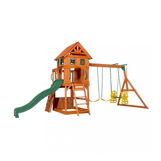
Atlantic
Wooden Swing Set
Model: #1608016
Owner's Manual
Frequently Asked Questions
Assembly Instructions
Warranty Information
Manufacturer: Backyard Discovery
3305 Airport Drive
Pittsburg, KS 66762
1-800-856-4445
Register your new swing set on-line @ www.swingsetsonline.com
(you will also find any updates on assembly instructions and
information to order replacement parts).
Features the
fastening system.
Save this assembly manual for future reference in the event that
you need to order replacement parts.
Made in China
Advertisement

Related Manuals for Backyard Discovery Atlantic Wooden Swing Set


Summary of Contents for Backyard Discovery Atlantic Wooden Swing Set
- Page 1 Wooden Swing Set Model: #1608016 Owner's Manual Frequently Asked Questions Assembly Instructions Warranty Information Manufacturer: Backyard Discovery 3305 Airport Drive Pittsburg, KS 66762 1-800-856-4445 Register your new swing set on-line @ www.swingsetsonline.com (you will also find any updates on assembly instructions and information to order replacement parts).
- Page 2 STOP PARE Missing A Part? CALL US BEFORE GOING BACK TO THE STORE! The store where you made your purchase does not stock parts for this item. If you have assembly questions or if you need parts, whether they are missing or damaged Call Toll-Free Help Line or visit www.swingsetsonline.com ¡LLÁMENOS ANTES DE REGRESAR A LA TIENDA! La tienda donde realizó...
- Page 3 Owner’s Manual Play Set Dear Customer: Please read entire booklet completely before beginning the assembly process. Equipment is recommended for use by children 3 to 10 years of age. Structures are not intended for public use. The Company does not warranty any of its residential structures subjected to commercial use such as: Daycare, Preschool, Nursery School, Recreational Park, or any similar Commercial Application.
- Page 4 Owner’s Manual Play Set Please refer to the Assembly section of the Assembly Manual for Maximum Fall Height Positioning Your Playcenter 1. The Playcenter is designed to be installed on a level surface by an Adult with an Adult helper. Place in a flat area of your yard to minimize ground preparation. 2.
- Page 5 Owner’s Manual Play Set The following chart explains the fall height in feet from which a life threatening head injury would not be expected Critical Heights in feet (m) of Tested Materials Material Uncompressed Depth Compressed Depth 6" (152mm) 9" (228mm) 12"...
- Page 6 Owner’s Manual Play Set 18. Verify that any suspended climbing ropes, chain, or cable are secured at both ends and that they cannot be looped back on it. 19. Instruct children not to attach items to the playground equipment that are not specifically designed for use with the equipment, such as, but not limited to, jump ropes, clothesline, pet leashes, cables and chain as they may cause a strangulation hazard.
- Page 7 Third Party Assembly: Customer may, in their sole discretion, elect to use a third party person or service to assemble this product. Backyard Discovery assumes no responsibility or liability for any charge incurred by the Customer for any assembly services’.
- Page 8 Owner’s Manual Play Set APPENDIX A Information on Playground Surfacing Materials: The following information is from the United States Consumer Product Safety Commission’s Information Sheet for playground surfacing material; also see the following website for additional information: www.cpsc.gov/cpscpub/pubs/323.html. ! "# $ %" &$' (") " "#& *% + , -) . " ( .,- "# /&0 /&# % (&...
- Page 9 Owner’s Manual Play Set $ (&-) -& "+ ! ( %"& * ) . )" (&)/% ")0 % ' %&"& ( %' -"& * "# 4)/&.&"+ ! ) + ')( " (&*#" )%% (" . & - -"& 6&"# ) + &" $ $ "&...
- Page 10 The stakes provided should be used to secure it firmly to the ground. 2. What size area is recommended for the playset? Backyard Discovery recommends at least a 6’ (six foot) perimeter around and above the playset for maximum safety. 3. What age range is appropriate for the playsets? Backyard Discovery playsets are recommended for children ages 3 –...
- Page 11 11. The end beam is not straight up and down. Why not? This is normal. Backyard Discovery designs playsets this way to ensure the strongest structure possible. The slight angle adds strength and reduces rocking and twisting.
- Page 12 Tools Required for Installation: (These are the tools that are generally required for assembly of our outdoor products. These tools are not included with the outdoor product purchase.) (Square) (Level 24") (Phillips Screw Driver) (Tape Measure) (Claw Hammer) (Drill Attachments: (Cordless Drill or Electric Drill) (7/16"...
- Page 13 Basic Setup Dimensions Place the set on level ground, not less than 6 ft [2 m] from any structure or obstruction such as a fence, garage, house, overhanging branches, laundry lines, or electrical wires. %' ( )*+, /' ( )*+, - !.
- Page 14 Parts Identification Wood Components (NOT TO SCALE) E1 - TOWER LEG - W102885 1 3/8"x3 3/8"x90 1/2" (36x86x2298) E2 - TOWER LEG - W102884 1 3/8"x3 3/8"x90 1/2" (36x86x2298) E3 - TOWER LEG - W100553 1 3/8"x3 3/8"x74" (36x86x1880) E4 - CLUB HOUSE LEG - W102883 1 3/8"x3 3/8"x43 3/8"...
- Page 15 Parts Identification Wood Components (NOT TO SCALE) H74 - LEFT UPRIGHT - W100608 1"x3 3/8"x50 3/4" (24x86x1290) H75 - RIGHT UPRIGHT - W100609 1"x3 3/8"x50 3/4" (24x86x1290) H76 - LADDER RUNG - W100611 1"x3 3/8"x18 1/8" (24x86x460) H79 - END SUPPORT - W100992 1"x3 1/2"x42"...
- Page 16 Parts Identification Wood Components (NOT TO SCALE) L3 - WALL RAIL - W100568 5/8"x4 3/8"x40" (16x112x1016) L5 - FLOOR BOARD - W100570 5/8"x4 3/8"x37 1/8" (16x112x942) L6 - BAY WINDOW HEADER - W100571 5/8"x4 3/8"x30 1/2" (16x112x774) L7 - GABLE MOON - W100572 5/8"x4 3/8"x13"...
- Page 17 Parts Identification Wood Components (NOT TO SCALE) M9 - WALL RAIL - W100581 5/8"x3 3/8"x37 1/2" (16x86x951) M10 - WALL BOARD - W100582 5/8"x3 3/8"x25" (16x86x634) M11 - WALL BOARD - W100583 5/8"x3 3/8"x20" (16x86x508) M12 - WALL BOARD - W100584 5/8"x3 3/8"x16 7/8"...
- Page 18 Parts Identification Wood Components (NOT TO SCALE) N3 - GABLE BOARD - W100590 5/8"x2 3/8"x31 1/2" (16x60x800) N4 - WALL BOARD - W100591 5/8"x2 3/8"x23" (16x60x584) N5 - BAY WINDOW BOARD - W100592 5/8"x2 3/8"x13 1/8" (16x60x332) N6 - GABLE BOARD - W100593 5/8"x2 3/8"x13"...
- Page 19 Parts Identification Hardware Y - LAG SCREW WH 5/16x1 1/2 - H100026 (11) CM - BOLT WH 5/16x1/2 - H100115 (20) Z - LAG SCREW WH 5/16x2 - H100027 F - BOLT WH 5/16x1 - H100008 (15) AA - LAG SCREW WH 5/16x2 1/2 - H100028 (36) H - BOLT WH 5/16x1 1/2 - H100010 KY - BOLT WH 1/4x1/2"...
- Page 20 Parts Identification Hardware BN - SCREW PFH 8x1 - H100085 (246) BR - SCREW PFH 8x1 1/8 - H100088 (97) BQ - SCREW PFH 8x1 1/4 - H100087 (66) BP - SCREW PFH 8x1 1/2 - H100086 (99) CK - SCREW PFH 8x2 - H100111 (26) BT - SCREW PFH 8x2 1/2 - H100090 (15)
- Page 21 Parts Identification Hardware B - NUT BARREL WH 5/16x5/8 - H100004 CB - WASHER SAFETY 17x30 - H100103 (66) D - NUT BARREL WH 5/16x7/8 - H100005 (24) CD - WASHER FLAT 8x27 - H100105 C - NUT BARREL WH 5/16x1 1/2 - H100006 CE - WASHER FLAT 9x18 - H100106 (19) E - NUT BARREL WH 5/16x1 3/4 - H100007...
- Page 22 Parts Identification Accessories (NOT TO SCALE) - T-30 Torx Bit - H100147 EK - SLIDE RAIL 8' GREEN RIGHT - A100054 - T-40 Torx Bit - A100042 EL - SLIDE RAIL 8' GREEN LEFT - A100055 EM - SLIDE BED 8' YELLOW - A100056 DN - GLIDER SEAT DARK GREEN - A100025 FB - SWING SEAT YELLOW - A100070 DO - CAPTAINS GLIDER ARM YELLOW - A100026...
- Page 23 Parts Identification Accessories (NOT TO SCALE) EV - CLIMBING ROCK - GREEN -A100064 ES - L BRACKET GREEN 32x51 -A100061 GD - L BRACKET 66x66x127 -A100140 EY - TUBING CAP GLIDER SUPPORT -A100067 EX - GLIDER BUSHING BYD GREEN EW - GLIDER SUPPORT BYD GREEN -A100066 -A100065 FX - HAND GRIP METAL GREEN 381 c/c...
- Page 24 SB74 - SWING BEAM - W102304 2"x5 1/4"x89 1/2" (50x134x2274) GD - L BRACKET 66x66x127 - A100140 QZ - TRIANGLE PLATE 100 5 HOLE - A100294 SWING BEAM ASSEMBLY STEP 1 BOLT WH ATTACH (2) QZ TRIANGLE PLATES TO SB74 SWING BEAM USING (3) 1-3/4" BOLTS, 5/16x1-3/4 LOCK WASHER AND 7/8"...
- Page 25 W71 - SWING BEAM SUPPORT - W102349 H79 - END SUPPORT - W100992 2"x3 3/8"x47 3/8" (50x86x1204) 1"x3 1/2"x42" (24x86x1072) E77 - ANGLE BRACE - W100991 H80 - GROUND BOARD - W100990 1 3/8"x3 3/8"x74 3/8" (36x86x1890) 1"x3 3/8"x87 3/8" (24x86x2218) STEP 2 INSERT (2) 2-1/2"...
- Page 26 EX - GLIDER BUSHING BYD GREEN - A100066 EY - TUBING CAP GLIDER SUPPORT - A100067 EW - GLIDER SUPPORT BYD GREEN - A100065 STEP 3 ATTACH (2) QZ TRIANGLE PLATES TO W71 SWING BEAM SUPPORT USING (2) 1-3/4" BOLTS, LOCK WASHERS AND 7/8" BOLT WH BARREL NUTS (FIG.1).
- Page 27 8 FOOT SLIDE ASSEMBLY PHASE 1 STEP 1 PLACE SLIDE BRACE CENTERED ON THE BOTTOM 1/4" FROM THE EDGE. TRANSFER HOLES ON THE BOARD THROUGH THE SLIDE BED AS SHOWN BELOW. USE A 3/8" DRILL BIT. ATTACH SLIDE BRACE TO SLIDE USING HARDWARE SHOWN. DESCRIPTION SLIDE BRACE BOLT WH 5/16x1/2...
- Page 28 8 FOOT SLIDE ASSEMBLY PHASE 2 STEP 2 PLACE 1 SLIDE RAIL ON A FLAT SURFACE AND BEGIN INSERTING SLIDE BED AT THE BOTTOM OF THE SLIDE RAIL (FIG. 1). PUT SLIDE SUPPORT BOTTOM INTO THE SUPPORT POCKET AT THE BOTTOM OF THE RAIL AND HAVE A HELPER BEND THE SLIDE BED TOWARDS THE TOP OF THE SLIDE AND INSERT THE BED INTO THE SLIDE CAVITY.
- Page 29 L1 - LEFT WALL RAIL - W102360 E1 - TOWER LEG - W102885 K1 - BASE BOARD - W100562 5/8"x4 3/8"x63 7/8" (16x112x1624) 1 3/8"x3 3/8"x90 1/2" (36x86x2298) 5/8"x5 1/4"x63 7/8" (16x134x1624) H2 - RIGHT FLOOR RAIL - W100558 N1 - SWING BLOCK - W100588 E2 - TOWER LEG - W102884 1"x3 3/8"x63 7/8"...
- Page 30 K2 - BASE BOARD - W100563 M6 - FLOOR RAIL - W100578 K3 - FRONT ARCH - W100564 5/8"x5 1/4"x40" (16x134x1016) 5/8"x3 3/8"x40" (16x86x1016) 5/8"x5 1/4"x40" (16x134x1016) M8 - WALL RAIL - W100580 L3 - WALL RAIL - W100568 L8 - CLUB HOUSE WALL RAIL - W100569 5/8"x3 3/8"x40"...
- Page 31 J1 - DECK BRACE - W100561 M3 - FLOOR BOARD - W100575 1"x2 3/8"x15 3/4" (24x60x400) 5/8"x3 3/8"x41 7/8" (16x86x1064) L5 - FLOOR BOARD - W100570 N2 - FLOOR BOARD - W100589 5/8"x4 3/8"x37 1/8" (16x112x942) 5/8"x2 3/8"x41 7/8" (16x60x1064) STEP 4 ATTACH (2) J1 DECK BRACES TO M6 FLOOR RAIL USING (2) BOLT WH...
- Page 32 M2 - FLOOR RUNNER - W100574 5/8"x3 3/8"x63 7/8" (16x86x1624) ES - L BRACKET GREEN 32x51 - A100061 STEP 6 ATTACH (2) ES L BRACKETS TO THE ENDS OF M2 FLOOR RUNNER USING (2) 3/4" TAPPING SCREWS. ATTACH ES L BRACKETS AND M2 FLOOR SCREW RUNNER TO M6 &...
- Page 33 M13 - WALL RAIL - W100585 M1 - WALL RAIL - W100573 5/8"x3 3/8"x8 1/4" (16x86x208) 5/8"x3 3/8"x63 7/8" (16x86x1624) M8 - WALL RAIL - W100580 M14 - WALL RAIL - W100586 5/8"x3 3/8"x40" (16x86x1016) 5/8"x3 3/8"x6 3/4" (16x86x172) STEP 7 ATTACH M1 WALL RAIL TO E1 &...
- Page 34 M13 - WALL RAIL - W100585 E4 - CLUB HOUSE LEG - W102883 5/8"x3 3/8"x8 1/4" (16x86x208) 1 3/8"x3 3/8"x43 3/8" (36x86x1102) ES - L BRACKET GREEN 32x51 - A100061 E5 - CLUB HOUSE LEG - W102882 M14 - WALL RAIL - W100586 1 3/8"x3 3/8"x43 3/8"...
- Page 35 M9 - WALL RAIL - W100581 L8 - CLUB HOUSE WALL RAIL - W100569 G1 - SWING BEAM MOUNT - W102365 5/8"x3 3/8"x37 1/2" (16x86x951) 5/8"x4 3/8"x40" (16x112x1016) 1"x5 1/4"x37 3/8" (24x134x950) STEP 9 USING A HAMMER, INSERT (4) 5/16 T-NUTS INTO G1 SWING BEAM MOUNT. BOLT WH 5/16x1-1/2 ATTACH M9 WALL RAIL TO E1 TOWER LEG AND E5 CLUB HOUSE LEG USING (4) 1- 1/2"...
- Page 36 N7 - GABLE BOARD - W100594 H3 - ROOF RAFTER - W100559 N3 - GABLE BOARD - W100590 5/8"x2 3/8"x8" (16x60x202) 1"x3 3/8"x34" (24x86x864) 5/8"x2 3/8"x31 1/2" (16x60x800) N6 - GABLE BOARD - W100593 L7 - GABLE MOON - W100572 5/8"x2 3/8"x13"...
-
Page 37: Table Of Contents
M17 - WALL RAIL - W102881 5/8"x3 3/8"x40" (16x86x1016) GABLE END ASSEMBLY STEP 11 MEASURE DOWN 15/16" FROM TOP OF E1 & E2 LEGS AND PILOT DRILL USING 1/8" DRILL BIT APPROXIMATELY 2" DEEP FOR H3 AND M8 BOARD ATTACHMENT. SEE FIGURE 1. - Page 38 M7 - WALL BOARD - W100579 M11 - WALL BOARD - W100583 N4 - WALL BOARD - W100591 5/8"x3 3/8"x40" (16x86x1016) 5/8"x2 3/8"x23" (16x60x584) 5/8"x3 3/8"x20" (16x86x508) STEP 13 ATTACH N4 WALL BOARDS TO M8 & L3 WALL RAILS USING (12) 1-1/8" WOOD SCREWS. SEE ILLUSTRATION FOR SPACING AND MOUNTING DIMENSIONS.
- Page 39 N8 - WALL BOARD SUPPORT - W100595 M5 - WALL BOARD - W100577 5/8"x2 3/8"x6 3/4" (16x60x170) 5/8"x3 3/8"x42" (16x86x1066) ES - L BRACKET GREEN 32x51 - A100061 STEP 14 ATTACH (4) M5 WALL BOARDS TO M17 & M13 WALL RAILS USING (16) 1-1/8" WOOD SCREWS.
-
Page 40: Step 15
M16 - WALL BOARD - W100599 M12 - WALL BOARD - W100584 5/8"x3 3/8"x42" (16x86x1066) 5/8"x3 3/8"x16 7/8" (16x86x428) M15 - WALL BOARD - W100587 M4 - WALL BOARD - W100576 5/8"x3 3/8"x4 1/8" (16x86x106) 5/8"x3 3/8"x42" (16x86x1066) ES - L BRACKET GREEN 32x51 - A100061 STEP 15 ATTACH (2) M4 &... - Page 41 K4 - TABLE TOP - W100565 H4 - TABLE SUPPORT - W100560 5/8"x5 1/4"x37" (16x134x940) 1"x2"x4" (24x51x102) GK - WINDOW FRAME 216x267 - A100146 STEP 16 ATTACH (2) GK WINDOW FRAMES TO THE OUTSIDE OF FORT USING (8) 3/4" PWH SCREWS.
- Page 42 N4 - WALL BOARD - W100591 M4 - WALL BOARD - W100576 5/8"x2 3/8"x23" (16x60x584) 5/8"x3 3/8"x42" (16x86x1066) STEP 18 ATTACH (4) N4 WALL BOARDS TO L1 LEFT WALL RAIL AND M1 WALL RAIL USING (8) 1-1/8" WOOD SCREWS. ATTACH (9) M4 WALL BOARDS TO M1, L1 AND M9 WALL RAIL USING (45) 1-1/8" WOOD SCREWS.
- Page 43 M10 - WALL BOARD - W100582 5/8"x3 3/8"x25" (16x86x634) STEP 19 ATTACH (2) M10 WALL BOARDS TO L2 RIGHT WALL RAIL AND M14 WALL RAILS USING (8) 1-1/8" WOOD SCREWS. SCREW PFH 8x1-1/8"...
- Page 44 N9 - BAY WINDOW BOARD - W100596 5/8"x2 3/8"x6 1/4" (16x60x158) L6 - BAY WINDOW HEADER - W100571 5/8"x4 3/8"x30 1/2" (16x112x774) N5 - BAY WINDOW BOARD - W100592 GK - WINDOW 216x267 GREEN - A100146 5/8"x2 3/8"x13 1/8" (16x60x332) STEP 20 STARTING IN THE CENTER, PILOT DRILL USING 1/8"...
-
Page 45: Lag Screw Wh 5/16X2-1/2
H74 - LEFT UPRIGHT - W100608 M73 - REAR SUPPORT - W100610 1"x3 3/8"x50 3/4" (24x86x1290) 5/8"x3 3/8"x19 1/4" (16x86x488) H76 - LADDER RUNG - W100611 H75 - RIGHT UPRIGHT - W100609 1"x3 3/8"x18 1/8" (24x86x460) 1"x3 3/8"x50 3/4" (24x86x1290) STEP 22 ATTACH (4) H76 LADDER RUNGS TO H74 LEFT UPRIGHT USING (8) 2"... - Page 46 R1 - ROOF BOARD - W100597 FX - HAND GRIP METAL GREEN 381 c/c - A100118 3/4"x5 1/2"x42 1/2" (18x140x1080) STEP 24 USING FX HAND GRIP AS A TEMPLATE, PILOT DRILL USING 7/16" BIT AND ATTACH TO E3 TOWER LEG USING (2) 1" BOLTS, LOCK WASHERS AND 7/8" BARREL NUTS. BOLT WH 5/16x1/2 BOLT WH...
- Page 47 N82 - ROCKWALL TOP CAP - W102364 H73 - ROCK WALL RAIL - W102361 5/8"x2 3/8"x20 1/4" (16x60x514) 24"x86"x1237" (24x86x1237) EV - CLIMBING ROCK - GREEN - A100064 M72 - ROCK WALL BOARD - W103331 N83 - ROCK WALL BOARD HOLES - W102363 5/8"x3 3/8"x20 1/4"...
- Page 48 STEP 28 CENTER SLIDE ASSEMBLY IN OPENING, AS SHOWN. BOLT WH USING THE DRILLING PATTERN BELOW, PILOT DRILL (3) HOLES INTO M3 FLOOR 5/16x1/2 BOARDS USING 7/16" DRILL BIT AND ATTACH SLIDE ASSEMBLY USING (3) 1/2" BOLTS, LOCK WASHERS AND 5/8" BARREL NUTS. WASHER LOCK EXT 12x19...
- Page 49 STEP 29 ATTACH SWING BEAM ASSEMBLY TO G1 SWING BEAM MOUNT USING (4) 1-1/4" HEX BOLTS, SPLIT WASHERS AND FLAT WASHERS. SCREW PWH 8x5/8 ATTACH HC ID PLATE TO SWING BEAM USING (4) 5/8" SCREWS, AS SHOWN. BOLT HEX 5/16x1-1/4 WASHER SPLIT 5/16 SWING BEAM ASSEMBLY...
- Page 50 Captians Glider WASHER FLAT 8x27 NUT LOCK 5/16 ROPE-CHAIN GREEN 45" BOLT WH 5/16x5 3/4 WASHER FLAT 8x27 NUT LOCK 5/16 QUICK LINK BOLT WH 5/16x5 3/4 CAPTAINS GLIDER ARM YELLOW GLIDER SEAT DARK GREEN...
- Page 51 KC - METAL GROUND STAKE BROWN - A100178 FB - SWING SEAT YELLOW - A100070 ZP - ROPE-CHAIN GREEN 51.25" - A100087 FA - QUICK LINK - A100069 ZN - ROPE-CHAIN GREEN 45" - A100095 Anchoring Instructions BOLT WH NOTE: 1/4x1/2"...
- Page 52 Limited Warranty. In addition, Backyard Discovery will replace any parts within the first 30 days from date of purchase found to be missing from or damaged in the original packaging.
Need help?
Do you have a question about the Atlantic Wooden Swing Set and is the answer not in the manual?
Questions and answers