Advertisement
Quick Links
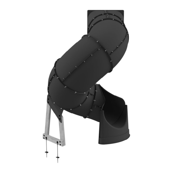
SPIRAL TUBE SLIDE
NOTES:
This spiral tube slide is designed to
ONLY fit a deck height of 5 feet with
an opening size of 25 1/2" x 27".
DO NOT climb on the outside of
spiral tube slide.
RESIDENTIAL USE ONLY.
SAVE THIS ASSEMBLY MANUAL FOR FUTURE REFERENCE IN THE EVENT THAT
Made in China | INS-9198012-A-TUBE SLIDE-LH-ENG 03-03-2020
Model # 9198012
assembly time may vary based on skill level
For the most up to date assembly manual,
to register your set, or to order replacement parts please visit
www.backyarddiscovery.com
YOU NEED TO ORDER REPLACEMENT PARTS.
Left Exit Slide
Owner's Manual & Assembly Instructions
average 2 person assembly time
MANUFACTURED BY:
Backyard Discovery
3305 Airport Drive
Pittsburg, KS 66762
800-856-4445
Advertisement

Related Manuals for Backyard Discovery 9198012


Summary of Contents for Backyard Discovery 9198012
- Page 1 For the most up to date assembly manual, to register your set, or to order replacement parts please visit www.backyarddiscovery.com SAVE THIS ASSEMBLY MANUAL FOR FUTURE REFERENCE IN THE EVENT THAT YOU NEED TO ORDER REPLACEMENT PARTS. Made in China | INS-9198012-A-TUBE SLIDE-LH-ENG 03-03-2020...
- Page 2 Owner’s Manual Please Read This Before Starting Assembly MISSING A PART? CALL US BEFORE GOING BACK TO THE STORE The store where you made your purchase does not stock parts for this item. If you have assembly questions or you are missing or have damaged parts, please call 1-800-856-4445 you can also visit www.backyarddiscovery.com...
-
Page 3: Limited Lifetime Warranty
In the event of any rot, decay or defect during the period, Backyard Discovery will remedy the defect as described herein, without charge to the purchaser for parts, as soon as practical. The remedy will consist of repair or replacement of the product, or refund of the purchase price, at the discretion of Backyard Discovery after opportunity to inspect the alleged defect or photographs thereof. - Page 4 Operating Instructions and Safety Warnings for Swing Sets and Accessories Owner’s Manual WARNING: BURN HAZARD • Pay special attention to plastic and metal surfaces as they may be hot enough to cause burns. • Always check the temperature of the product before NOTE: letting your children play on it.
- Page 5 Owner’s Manual Please Read This Before Starting Assembly Positioning Your Playcenter Suggested Playground Surfacing The play center is designed to be installed on a level Do not install home playground equipment over • • surface by an adult with an adult helper. Place in a fl at concrete, asphalt, packed earth, grass, carpet, or any area of your yard to minimize ground preparation.
- Page 6 Owner’s Manual Please Read This Before Starting Assembly APPENDIX A X3.1.3.2 Do not install loose- ll surfacing over hard The following information is from the United States surfaces such as concrete or asphalt. Consumer Product Safety Commission’s Information X3.1.4 Poured-In-Place Surfaces or Pre-Manufactured Sheet for playground surfacing material;...
-
Page 7: Instructions For Proper Maintenance
Check all moving parts including swing seats, third party person or service to assemble this product. ropes, cables, and chains for wear, rust, or other Backyard Discovery assumes no responsibility or deterioration. Replace as needed. liability for any charge incurred by the Customer for any assembly services’... -
Page 8: Assembly Tips
Owner’s Manual Assembly Tips ASSEMBLY TIP: Keep and eye out for these boxes which will contain helpful pictures and information making the assembly process as quick and painless as possible. Hardware Identi cation Hardware bags are printed with a seven digit alpha-numeric part number. - Page 9 Owner's Manual Basic Setup Dimensions & Assembly Notes Place the set on level ground, not less than 6 ft 7 in [2 m] from any structure or obstruction such as a fence, garage, house, overhanging branches, laundry lines, or electrical wires. •...
- Page 10 Proper Placement of Spiral Tube Slide Owner's Manual SLIDE OBSTRUCTS SWING SAFETY AREA SWING SAFETY AREA SWING SAFETY AREA SLIDE EXIT IS CLEAR FROM OBSTACLES SLIDE EXIT ENTERS SWING SAFETY AREA...
-
Page 11: Parts Identification
Owner's Manual Parts Identification Wood Components (Not to Scale) UPRIGHT - W4L12583 GROUND BOARD - W4L12585 1 3/8"x3 3/8"x19 7/8" (36x86x505) 1 3/8"x3 3/8"x21" (36x86x533) (x1) (x1) UPRIGHT - W4L12584 1 3/8"x3 3/8"x29 1/4" (36x86x743) (x1) Hardware Components H100769 BOLT PTH WZ H100195 BOLT WH BLK (x134) - Page 12 Owner's Manual Parts Identification Accessory Components (Not to Scale) A6P00302-2 SLIDE ENTRANCE LEFT (x1) A6P00302-1 SLIDE ENTRANCE RIGHT (x1) A6P00302-4 SLIDE ELBOW (x9) A6P00302-3 STRAIGHT TUBE (x2) A6P00302-5L EXIT TOP (x1) A6P00302-6L EXIT SUPPORT (x1)
- Page 13 Owner's Manual Parts Identification Accessory Components (Not to Scale) A100178 METAL GROUND STAKE BROWN (x2) A4M00996 TUBE SLIDE BRACKET (x36) A4M01002 TUBE SLIDE BRACKET - LH (x1)
- Page 14 Phase 1 STEP 1 H100769 BOLT PTH WZ (x8) 1/4x3/4 H100148 NUT LOCK WZ (x8) A6P00302-2 A6P00302-1 SLIDE ENTRANCE LEFT SLIDE ENTRANCE RIGHT (x1) (x1) TIP: (x8) BOLT - 3/4" LAYING THE PARTS ON THEIR FLAT END MAKES ASSEMBLY EASIER. (x8) NUT - 1/4"...
- Page 15 STEP 2 Phase 1 H100769 BOLT PTH WZ (x8) 1/4x3/4 A6P00302-3 H100148 NUT LOCK WZ STRAIGHT TUBE (x2) (x8) (x8) NUT - 1/4" (x8) BOLT - 3/4" THE "L" LAYOUT SHOULD BE THE SAME AS THE IMAGE SHOWN. 302-3 (x2) STRAIGHT TUBE...
- Page 16 STEP 3 Phase 1 H100769 BOLT PTH WZ (x32) 1/4x3/4 A6P00302-4 SLIDE ELBOW H100148 NUT LOCK WZ (x8) (x32) (x8) NOTE: BOLT - 3/4" REPEAT THIS STEP (3) MORE TIMES. (x8) NUT - 1/4" 302-4 (x2) SLIDE ELBOW...
- Page 17 Phase 1 STEP 4 H100769 BOLT PTH WZ (x8) 1/4x3/4 A6P00302-4 H100148 NUT LOCK WZ SLIDE ELBOW A6P00302-5L (x1) EXIT TOP (x8) (x1) (x8) BOLT - 3/4" 302-4 (x8) (x1) NUT - 1/4" SLIDE ELBOW 302-5L (x1) EXIT TOP...
- Page 18 STEP 5 Phase 1 H100148 NUT LOCK WZ H100769 BOLT PTH WZ (x5) (x7) 1/4x3/4 A6P00302-6L EXIT SUPPORT (x1) FRONT VIEW TIP: • RECOMMENDED BOLT ASSEMBLY ORDER, FROM TOP LEFT AS YOU ALIGN HOLES. • MAKE SURE THE EXIT SUPPORT IS ALIGNED WITH THE SLIDE ELBOW AS SHOWN BELOW.
- Page 19 Phase 2 REFERENCE IMPORTANT: BRACKET CONFIGURATION ASSEMBLY & PLACEMENT. 1 HOLE 3 HOLES 2 HOLES CONFIGURATION 'A' DIAGRAM CONFIGURATION 'B' DIAGRAM NOTE ALIGNMENT MARKINGS NOTE ALIGNMENT MARKINGS CONFIGURATION 'A' CONFIGURATION 'B' NOTE: PAY CLOSE ATTENTION TO THE ALIGNMENT MARKINGS ON EACH SLIDE SECTION.
- Page 20 STEP 1 Phase 2 H100769 BOLT PTH WZ (x12) 1/4x3/4 (1)-STRAIGHT TUBE SUB-ASSEMBLY (1)-ENTRANCE SUB-ASSEMBLY H100148 NUT LOCK WZ (x12) A4M00996 TUBE SLIDE BRACKET (x6) (x12) NOTE: NUT - 1/4" THIS SECTION ASSEMBLY USES (x3) BRACKET CONFIGURATION 'A' TUBE SLIDE BRACKET SHOWN IN REFERENCE PAGE.
- Page 21 STEP 2 Phase 2 H100769 BOLT PTH WZ (x12) 1/4x3/4 A4M00996 TUBE SLIDE BRACKET (x6) H100148 NUT LOCK WZ (x12) (1)-ELBOW TUBE SUB-ASSEMBLY NOTE: • ALIGN THE 'L' AND THE 'ARROW' TO ACHIEVE THE PROPER POSITION WHEN ASSEMBLING THE SLIDE. •...
- Page 22 STEP 3 Phase 2 H100769 BOLT PTH WZ (x12) 1/4x3/4 A4M00996 TUBE SLIDE BRACKET (x6) H100148 NUT LOCK WZ (x12) (1)-ELBOW TUBE SUB-ASSEMBLY NOTE: • ALIGN THE 'L' AND THE 'ARROW' TO ACHIEVE THE PROPER POSITION WHEN ASSEMBLING THE SLIDE. •...
- Page 23 STEP 4 Phase 2 H100769 BOLT PTH WZ (x12) 1/4x3/4 A4M00996 TUBE SLIDE BRACKET (x6) H100148 NUT LOCK WZ (x12) (1)-ELBOW TUBE SUB-ASSEMBLY NOTE: NOTE: • ALIGN THE 'L' AND THE 'ARROW' TO ACHIEVE THE PROPER POSITION WHEN ASSEMBLING THE SLIDE. •...
- Page 24 STEP 5 Phase 2 H100769 BOLT PTH WZ A4M00996 TUBE SLIDE BRACKET (x6) (x9) 1/4x3/4 H100148 NUT LOCK WZ (x12) (1)-ELBOW TUBE SUB-ASSEMBLY H100795 BOLT PTH WZ A4M01002 (x3) 1/4x7/8 TUBE SLIDE BRACKET - LH (x1) NOTE: • ALIGN THE 'L' AND THE 'ARROW' TO ACHIEVE THE PROPER POSITION WHEN ASSEMBLING THE SLIDE.
- Page 25 STEP 6 Phase 2 H100769 BOLT PTH WZ (x12) 1/4x3/4 A4M00996 TUBE SLIDE BRACKET H100148 NUT LOCK WZ (x6) (x12) (1)-EXIT SUB-ASSEMBLY NOTE: • ALIGN THE 'L' AND THE 'ARROW' TO ACHIEVE THE PROPER POSITION WHEN ASSEMBLING THE SLIDE. • NOTE THIS SECTION ASSEMBLY USES CONFIGURATION 'B' SHOWN IN THE REFERENCE PAGE.
- Page 26 STEP 1 Phase 3 H100195 BOLT WH BLK GROUND BOARD - W4L12585 UPRIGHT - W4L12583 (x4) 5/16x2-3/4 (x1) 1 3/8"x3 3/8"x21" (36x86x533) (x1) 1 3/8"x3 3/8"x19 7/8" (36x86x505) H100379 T-NUT BLK (x4) 5/16 UPRIGHT - W4L12584 H100198 WASHER LOCK EXT BLK 1 3/8"x3 3/8"x29 1/4"...
- Page 27 STEP 2 Phase 3 H100407 BOLT WH BLK (x4) 5/16x1 1/2 (1)-SLIDE BRACE SUB-ASSEMBLY H100379 T-NUT BLK (1)-TUBE SLIDE SUB-ASSEMBLY (x4) 5/16 NOTE: HAMMER T-NUTS INTO PROVIDED HOLES IN 'E85' AND 'E86'. (x4) (x4) T-NUT - 5/16" BOLT - 1 1/2" (1)-SLIDE BRACE SUB-ASSEMBLY...
- Page 28 STEP 3 Phase 3 WASHER LOCK H100459 BOLT WH BLK H100199 NUT BARREL EXT BLK H100192 5/16x1 1/4 WH BLK A100178 12x19 METAL GROUND STAKE BROWN (x2) 5/16x7/8 (x2) WASHER - 12x19 (x2) (x2) NUT BARREL - 7/8" BOLT - 1 1/4" (x2) METAL GROUND STAKE BROWN...
- Page 29 Attaching Spiral Tube Slide To Play Set Phase 4 Recommended to use (x18) #8 x 1" PWH screws to attach slide to play set. Screws are provided by others. The slide attachment frame on the play set needs to be at a minimum of 1 3/8" [35mm] thick.
Need help?
Do you have a question about the 9198012 and is the answer not in the manual?
Questions and answers