
Related Manuals for Beckhoff CP65 Series


Summary of Contents for Beckhoff CP65 Series
- Page 1 Installation and Operating instructions for Built-in Panel PC CP65xx from -0080 Version: 3.0 Date: 2020-04-23...
-
Page 3: Table Of Contents
Table of contents Table of contents Foreword Notes on the Documentation Liability Conditions Trademarks Patent Pending Copyright State at Delivery Delivery conditions Description of safety symbols Basic safety measures Operator’s obligation to exercise diligence Operator requirements Product Description Appropriate Use Structure Interfaces from CP65xx-0080 PS/2 connections... - Page 4 Table of contents Beckhoff Support and Service Beckhoff branches and partner companies Beckhoff company headquarters Beckhoff Support Beckhoff Service Assembly dimensions Appendix Technical data Approvals FCC: Federal Communications Commission Radio Frequency Interference Statement FCC: Canadian Notice CP65xx...
-
Page 5: Foreword
Beckhoff Automation GmbH & Co.KG. Delivery conditions In addition, the general delivery conditions of the company Beckhoff Automation GmbH & Co.KG apply. CP65xx... -
Page 6: Description Of Safety Symbols
Foreword Description of safety symbols The following safety symbols are used in this operating manual. They are intended to alert the reader to the associated safety instructions. This symbol is intended to highlight risks for the life or health of personnel. Danger This symbol is intended to highlight risks for equipment, materials or the environment. -
Page 7: Basic Safety Measures
Foreword Basic safety measures Only switch the PC off after Before the Industrial PC is switched off, software that is running must closing the software be properly closed. Otherwise it is possible that data on the hard disk is lost. Please read the section on Switching the Industrial PC on and off. -
Page 8: Operator's Obligation To Exercise Diligence
Foreword Operator’s obligation to exercise diligence The operator must ensure that • the Industrial PC is only used for its intended use (see also chapter Product Description). • the Industrial PC is in a sound condition and in working order during operation. -
Page 9: Product Description
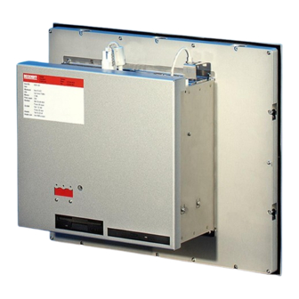
Product Description Product Description Appropriate Use The CP65xx add-on Industrial PC is designed to be used in association with the built-in Control Panel and fitted into control cabinets in machine and plant engineering applications. Structure Rear view of the CP65xx Opening the housing In order to open the PC housing, first remove the fastening screw (see photo above) using a cross-head screwdriver. - Page 10 Product Description Folding out the inner chassis The chassis can now simply be folded out backwards, thus providing access to the hard drive, processor, memory and plug-in cards. View of the open PC When the inner chassis (1) has been folded out of the way with the hard drive (2), a 7-slot ATX motherboard (3) is found.
-
Page 11: Interfaces From Cp65Xx-0080
Product Description Interfaces from CP65xx-0080 ATX motherboard interfaces PS/2 connections PS/2 The upper PS/2 connector (X104) allows a PS/2 mouse to be used, while a PC keyboard can be connected to the lower PS/2 connector (X103). USB interfaces USB1 – USB4 The four USB interfaces (X108 –... -
Page 12: Further Interfaces
Product Description Further Interfaces Further USB interfaces Further USB-Interfaces The USB interfaces (14) and (15) are used to connect further USB peripheral devices. USB1.1 standard with a maximum data rate of 1.5 or 12 Mbps is supported. Additional plug-in cards (optional) Type plate There is a type plate on the top of the Industrial PC which provides information about the hardware configuration of the Industrial PC at the... -
Page 13: Installation Instructions
4. Please keep the associated paperwork. It contains important information for handling the unit. 5. Check the contents for visible shipping damage. 6. If you notice any shipping damage or inconsistencies between the contents and your order, you should notify Beckhoff Service. CP65xx... -
Page 14: Installation Of The Pc In The Control Cabinet
Installation Instructions Installation of the PC in the control cabinet The Built-in Panel PC CP65xx is designed for mounting in control cabinets in machine and plant engineering applications. The ambient conditions specified for operation must be observed (see the section on Technical data). -
Page 15: Power Supply Connection
Installation Instructions Power Supply Connection Supplied mains power unit The Industrial PC is fitted with a • 100-240 V , 50-60 Hz power supply unit (standard) or • with a 24 V power supply unit (Optional an uninterruptible power supply (UPS) can be realized using the battery pack C9900-U330). Danger of Explosion if using other battery packs! Danger Pin assignment of the connector... -
Page 16: Pin Assignment And Cable Requirements
Installation Instructions Coding pieces The connectors are coded differently at the factory, using snap-on coding pieces, according to the power supply unit that has been fitted. Differently coded plug connectors Coding for the 24 V power supply Coding for the 100-240 V 50-60 Hz power supply unit unit Pin assignment and cable requirements... -
Page 17: Fitting The Power Supply Cable
Installation Instructions Fitting the Power Supply Cable A 5-pin female plug connector with CAGE CLAMP connection and insertion catches is supplied along with a snap-on strain relief housing in order to assemble the PC power supply cable. Female plug connector is This female plug connector is also coded at the factory, according to the correspondingly coded type of power supply fitted, so that the plug, when assembled, will fit the... -
Page 18: Connecting Power Supply
Installation Instructions Connecting Power Supply The external wiring consists of the connection of the power supply, the battery pack (optional) and the connection of customized components for shutting down the PC. Cable Cross Sections Cable-cross-section for For the connection of the power supply, wiring with a cable-cross-section of connection of power supply 1.5 mm must be used. -
Page 19: Wiring Diagram
Installation Instructions Wiring diagram Wiring according to the wiring diagram (the circuit of PC_ON and Power- Status is symbolical): Wiring diagram external switch and power supply Connection of the Battery Pack and UPS Output only in combination with integrated UPS (order option). CP65xx... -
Page 20: Connecting Devices
Installation Instructions Connecting devices The power supply plug must be withdrawn! Warning Please read the documentation for the external devices prior to connecting them. During thunderstorms, plug connector must neither be inserted nor removed. When disconnecting a plug connector, always handle it at the plug. Do not pull the cable! Connecting cables The connections are located at the side of the Industrial PC and at the rear... -
Page 21: Operating Instructions
Operating Instructions Operating Instructions Please also refer to chapter Product Description. Switching the Industrial PC on and off Switch on The Industrial PC does not have its own mains switch. The Industrial PC will start when the equipment is switched on, or when it is connected to the power supply. -
Page 22: Keyboard Codes
Operating Instructions Keyboard codes Type-dependent number of Depending on the precise type, the Control Panel can have fewer keys keys than those described here. Operation The cursor is the blinking character that marks the point at which the next character entered will be displayed. The cursor is also known as the insertion point. - Page 23 Operating Instructions The meaning of the function keys, F1 to F10, is determined by the software and is displayed at the bottom edge of the display. The function of the special keys above the display is also determined by i n s c h u b i n s c h u b i n s c h u b i n s c h u b...
-
Page 24: Servicing And Maintenance
Operating Instructions Servicing and maintenance Please also refer to chapter Product Description. Cleaning the Industrial PC Switch off the Industrial PC and all connected devices, and disconnect the Industrial PC from the power supply. Danger The Industrial PC and the front of the Panel can be cleaned with a soft, damp cloth. -
Page 25: Troubleshooting
Nothing happens after the Industrial No power supply to the Industrial Check power supply cable PC has been switched on Other cause Call Beckhoff Service The Industrial PC does not boot Floppy disk or CD in drive Remove floppy disk or CD fully... - Page 26 Please contact your Beckhoff branch office or partner company for local support and service on Beckhoff products! The contact addresses for your country can be found in the list of Beckhoff branches and partner companies: www.beckhoff.com You will also find further documentation for Beckhoff components there.
- Page 27 Assembly dimensions Assembly dimensions The assembly of the unit must take place with the orientation diagrammed here. Warning All dimensions are in mm. Built-in Panel PC CP65xx Rear view Side view Display only CP6500 10"-Display CP6501 12"-Display 372.2 342.2 358.2 328.2 17.3 CP6502...
- Page 28 Appendix Appendix Technical data Dimensions Dimensions (W x H x D): 333 x 308 x 165 mm (without Control Panel) Weight: 10.1 kg (basic version, without Control Panel) Do not use the PC in areas The Industrial PC may not be used in areas of explosive hazard. of explosive hazard The following conditions must be observed during operation: Environmental conditions...
Need help?
Do you have a question about the CP65 Series and is the answer not in the manual?
Questions and answers