Table of Contents
Advertisement
Quick Links
Advertisement
Table of Contents

Related Manuals for Beckhoff C6032


Summary of Contents for Beckhoff C6032
- Page 1 C6032 | Industrial PC Manual | EN 2/20/2020 | Version: 1.0...
-
Page 3: Table Of Contents
Table of contents Table of contents 1 Notes on the documentation ........................ 5 2 For your safety............................ 6 Description of safety symbols ...................... 6 Intended use ............................ 6 Fundamental safety instructions ...................... 7 Operator's obligation to exercise diligence .................. 7 3 Product overview............................ 8 Structure ............................ 9 Name plate ............................ 13 4 Commissioning............................ 14 Transport and unpacking ......................... 14 Installation in the control cabinet ..................... 14... - Page 4 Table of contents Version: 1.0 Industrial PC...
-
Page 5: Notes On The Documentation
Copyright © Beckhoff Automation GmbH & Co. KG. The reproduction, distribution and utilization of this document as well as the communication of its contents to others without express authorization are prohibited. Offenders will be held liable for the payment of damages. All rights reserved in the event of the grant of a patent, utility model or design. -
Page 6: For Your Safety
Disregarding the notice may lead to damage to property. Intended use The C6032 is an Industrial PC for space-saving installation in the control cabinet. It is intended for use as a control system for automation, visualization and communication in machine construction and plant engineering. -
Page 7: Fundamental Safety Instructions
For your safety Improper use Do not use the Industrial PC in the following areas: • potentially explosive atmospheres • Areas with extreme environmental conditions, such as particularly high or low temperatures above and below the operating temperature range • Areas in which the device is loaded beyond the EMC interference immunity •... -
Page 8: Product Overview
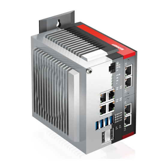
Product overview Fig. 1: C6032 The C6032 Industrial PC extends the range of ultra-compact Industrial PCs by a high-performance modular device for installation in the control cabinet. The second board level for modular interface and function extensions enables adaptation to specific applications and requirements. Various compact PCle modules are available as ordering options for this. -
Page 9: Structure
Product overview Structure Fig. 2: C6032 structure – basic configuration Table 1: Key - C6032 structure Component Description Protective conductor connection Low-resistance protective earthing of the Industrial PC Power supply (X101) Connection of the power supply and external wiring of the Industrial... -
Page 10: Fig. 3 C6032_Standard Connections
Product overview Fig. 3: C6032_standard connections Power supply (X101) The Industrial PC is equipped with a 24 V power supply unit. The power supply and external wiring are connected to the Industrial PC via the 4-pin voltage connector (Phoenix DFMC 4.5/2-STF-3.5 BK – 1708595). -
Page 11: Fig. 5 C6032_Status Leds
Product overview Protective conductor connection (PE) The low-resistance protective earthing of the Industrial PC must be established via the screw connection. The cabling in the control cabinet must be done in accordance with EN 60204-1:2006 PELV (Protective Extra Low Voltage) so that one side of the circuit or one point of the energy source of this circuit is connected to the protective conductor system. -
Page 12: Fig. 6 C6032_Modules
Product overview Interface options Fig. 6: C6032_modules You can extend the Industrial PC beyond the basic equipment level by additional interfaces. The following PCle Compact modules are available to you for this: • USB 3.0 • Network connections RJ-45 Ethernet 100/1000BASE-T •... -
Page 13: Name Plate
Product overview Name plate The name plate provides information on the equipment fitted to the Industrial PC. It is located on the right side panel of the housing. Fig. 7: C6032_name plate Table 4: Key to name plate Description Manufacturer, including address Model: The last four digits indicate the device generation. -
Page 14: Commissioning
5. Check the contents for visible shipping damage. 6. Inform the Beckhoff Service Dept. in case of discrepancies between the packaging content and the or- der or in the event of transport damage. Installation in the control cabinet The C6032 Industrial PC is designed for installation in control cabinets in machine and plant technology. -
Page 15: Fig. 8 C6032_Mounting Plates
Commissioning Fig. 8: C6032_mounting plates Figure 8 shows the two available mounting plates. In both cases, the plate is screwed to the right side panel of the Industrial PC. You can rotate both mounting plates before screwing on so that the PC can be mounted in the desired orientation for the cable entry in the control cabinet. -
Page 16: Dimensions
Commissioning 4.2.1 Dimensions The dimensions of the Industrial PC and the mounting plate are used to prepare the control cabinet and to mount the device correctly in the control cabinet. NOTE Mounting the device in a different way to that shown in the illustration may result in damage to the device. •... -
Page 17: Preparation Of The Control Cabinet
Commissioning Mounting plate on the side panel Ø 4,2 PCIe - module M4 grounding power - port ethernet - port USB 3.0 - port display - port Seitenansicht Rückansicht Vorderansicht Draufsicht Fig. 10: C6032_Mounting plate on the side panel 4.2.2 Preparation of the control cabinet The control cabinet must be equipped with the drill holes for the fastening screws according to the device dimensions of the PC (see chapter 4.2.1 Dimensions) NOTE... -
Page 18: Connecting The Industrial Pc
Commissioning Connecting the Industrial PC CAUTION Risk of electric shock! Connecting the Industrial PC during a thunderstorm can lead to electric shocks. • Never plug in or unplug the Industrial PC's cables during a thunderstorm. Earthing measures The low-resistance protective earthing of the Industrial PC must be established via the screw connection. Connect the earthing point on the Industrial PC (see chapter 3.1 Structure) with a low-resistance connection to the central earthing point of the panel in the control cabinet into which the PC is installed. -
Page 19: Operation
Operation Operation Switching the Industrial PC on and off The Industrial PC does not have its own mains switch. The Industrial PC will start when the equipment is switched on, or when it is connected to the power supply. NOTE Shutting down the Industrial PC before terminating the running software can result in loss of data. -
Page 20: Decommissioning
Operation Decommissioning Disposal of the Industrial PC Be sure to observe the national electronic scrap regulations when disposing of the Industrial PC. In order to dispose of the device, it must be removed and fully dismantled. Dispose of the components in the following way: •... -
Page 21: Maintenance
Maintenance Maintenance Cleaning DANGER Risk of electric shock! Cleaning the Industrial PC when it is switched on and connected to the power supply will lead to death or serious injury. • Switch off the Industrial PC and all connected devices. •... -
Page 22: Replacing The Battery
Inserting the wrong type of battery can cause an explosion and damage the device. • Replace the battery only by one of the same type or by a replacement type recommended by Beckhoff. • When replacing the battery, make sure that the polarity is correct. -
Page 23: Replacing The Fan
The Industrial PC may be damaged if the wrong type of fan is installed. • Replace the fan only by the identical type or by a replacement type approved by Beckhoff. To replace the fan, follow the steps below, which are shown in Figure 12: 1. -
Page 24: Troubleshooting
No power supply to the Industrial Check the cable for the power Industrial PC has been switched on supply Other cause Call Beckhoff Service The Industrial PC does not boot Setup settings are incorrect Check the setup settings fully Other cause... -
Page 25: Technical Data
Technical data Technical data Table 7: Technical data Product designation C6032 Dimensions (W x H x D) 129 x 133 x 104 mm, without mounting plate Weight Approx. 2100 g excluding mounting plate Approx. 2350 g including mounting plate Supply voltage... -
Page 26: Appendix
Phone: + 49 (0) 5246/963-0 Fax: + 49 (0) 5246/963-198 E-mail: info@beckhoff.de The addresses of the worldwide Beckhoff branches and agencies can be found on our website at http:// www.beckhoff.com/. You will also find further documentation for Beckhoff components there. -
Page 27: Approvals
Appendix Approvals FCC approvals for the United States of America FCC: Federal Communications Commission Radio Frequency Interference Statement This device was tested and complies with the limits for a digital device of class A, according part 15 of the FCC regulations. These limits are designed to provide adequate protection against adverse interference, if the device is used in a commercial environment. - Page 28 List of figures List of figures Fig. 1 C6032 ............................Fig. 2 C6032 structure – basic configuration ..................Fig. 3 C6032_standard connections ...................... Fig. 4 C6032_voltage connector......................Fig. 5 C6032_Status LEDs ........................Fig. 6 C6032_modules........................... Fig. 7 C6032_name plate ........................
- Page 29 List of tables List of tables Table 1 Key - C6032 structure........................Table 2 Pin assignment voltage connector....................Table 3 Meaning of the Status LEDs ......................Table 4 Key to name plate........................Table 5 Mounting plate ordering options ....................Table 6 Troubleshooting ...........................
- Page 30 Beckhoff Automation GmbH & Co. KG Hülshorstweg 20 D-33415 Verl www.beckhoff.com info@beckhoff.com More Information: www.beckhoff.com/C6032/...
Need help?
Do you have a question about the C6032 and is the answer not in the manual?
Questions and answers