Table of Contents
Advertisement
Quick Links
Advertisement
Chapters
Table of Contents

Related Manuals for Beckhoff CX9020


Summary of Contents for Beckhoff CX9020
- Page 1 Manual | EN CX9020 Embedded PC 2024-01-08 | Version: 2.5...
-
Page 3: Table Of Contents
Safety instructions .......................... 9 Notes on information security...................... 10 3 Transport and storage .......................... 11 4 Product overview ............................ 12 Structure of the CX9020 Embedded PC .................. 13 Name plate ............................ 14 Types .............................. 14 Architecture overview ........................ 16 5 Interface description .......................... 17 USB (X100, X101, X102, X103) ...................... - Page 4 12.1 Removing cables.......................... 64 12.2 Dismantling the Embedded PC ....................... 64 13 Technical data ............................ 66 14 Appendix .............................. 68 14.1 Accessories ............................. 68 14.2 Certifications ........................... 69 14.3 Support and Service........................ 70 List of tables ............................ 71 List of figures............................ 72 Version: 2.5 CX9020...
-
Page 5: Notes On The Documentation
EP1590927, EP1789857, EP1456722, EP2137893, DE102015105702 and similar applications and registrations in several other countries. ® EtherCAT is registered trademark and patented technology, licensed by Beckhoff Automation GmbH, Germany Copyright © Beckhoff Automation GmbH & Co. KG, Germany. The distribution and reproduction of this document, as well as the use and communication of its contents without express authorization, are prohibited. -
Page 6: Representation And Structure Of Warnings
There is a potential hazard to the environment and equipment. Notes showing further information or tips: This notice provides important information that will be of assistance in dealing with the product or software. There is no immediate danger to product, people or environment. Version: 2.5 CX9020... -
Page 7: Documentation Issue Status
Chapter NOVRAM added, Chapter 1-second UPS revised Documentation restructured and revised Notes on operation in hazardous areas added. Chapter Beckhoff Device Manager revised Chapter "RS232 (N030)" adapted. Chapter "Power supply" adapted. Chapter Technical data adapted. Chapters "Product Overview" and "Device Manager"... -
Page 8: For Your Safety
Beckhoff Automation GmbH & Co. In addition, the following actions are excluded from the liability of Beckhoff Automation GmbH & Co. KG: • Failure to comply with this documentation. -
Page 9: Safety Instructions
• Observe the relevant EMC guidelines for your application. • Avoid polarity reversal of the data and supply cables, as this may cause damage to the equipment. CX9020 Version: 2.5... -
Page 10: Notes On Information Security
• The sensitivity of a PC against malicious software increases with the number of installed and active software. • Uninstall or disable unnecessary software. Further information on the safe handling of networks and software can be found in the Beckhoff Information System: http://infosys.beckhoff.com... -
Page 11: Transport And Storage
PC must be protected from • high mechanical stress and • use the original packaging for shipping. Table 1: Dimensions and weight. CX9020 Dimensions (W x H x D) 84 mm x 100 mm x 91 mm Weight approx. -
Page 12: Product Overview
NOVRAM and are available again after a restart. The CX9020 Embedded PC can be ordered ex factory with a 1-second UPS (CX9020-U900). The 1-second UPS enables up to 1 MB of persistent data to be saved to the MicroSD card in the event of a loss of power. -
Page 13: Structure Of The Cx9020 Embedded Pc
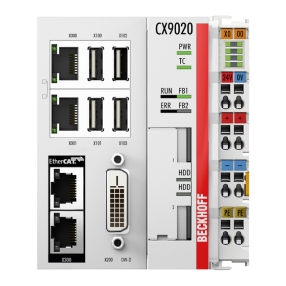
Product overview Structure of the CX9020 Embedded PC Fig. 1: Structure of the CX9020 Embedded PC. Table 3: Legend for the configuration. Component Description Optional interface (X300). Space for interfaces such as RS232, EtherCAT, CANopen or others. The optional interface must be ordered ex factory and cannot be retrofitted retrospectively. -
Page 14: Name Plate
License sticker for operating system (optional). Types The CX9020 Embedded PC can be ordered with different software options. Use this overview in conjunction with the information on the name plate to ascertain the operating system and the TwinCAT version of the Embedded PC. -
Page 15: Table 5 Cx9020 (1 Ghz 1 Core), Ordering Information For Software
Product overview The CX9020 Embedded PC is available with the following software options: Table 5: CX9020 (1 GHz 1 core), ordering information for software. Module Windows TwinCAT 2 TwinCAT 2 TwinCAT 3 operating Embedded TwinCAT PLC runtime NC runtime system Compact 7... -
Page 16: Architecture Overview
Product overview Architecture overview The architecture of the CX9020 Embedded PC is described below. ® The CX9020 Embedded PC is based on the ARMv7-A microarchitecture developed by ARM . The following CPU is used in the CX9020: • i.MX535 Cortex Details for the CPU can be read at ARM. -
Page 17: Interface Description
Both Ethernet interfaces reach speeds of 10 / 100 Mbit. The LEDs on the left of the interfaces indicate the connection status. The upper LED (LINK/ACT) indicates whether the interface is connected to a network. If this is the case the LED is yellow. The LED flashes when data transfer on the interface is in progress. CX9020 Version: 2.5... -
Page 18: Table 7 Ethernet Interface X000 And X001, Pin Assignment
Mbit the LED is green. Table 7: Ethernet interface X000 and X001, pin assignment. Signal Description TD + Transmit + TD - Transmit - RD + Receive + connected not used RD - Receive - connected not used Version: 2.5 CX9020... -
Page 19: Dvi-D (X200)
The DVI-D interface (X200) transfers digital data and is suitable for connection to digital displays. The resolution on the display or the Beckhoff Control Panel depends on the distance from the display device. The maximum distance is 5 m. Beckhoff offers various panels with an integrated DVI extension. A cable length of up to 50 meters is therefore possible. -
Page 20: Audio Interface (N020)
Table 10: Line In /Line Out jack plugs, pin assignment. Signal Description Left channel Right channel Ground Ground The only existing channel is transferred via the tip, the remainder of the sleeve is used for earthing. Fig. 9: Mic In X301 jack plug. Version: 2.5 CX9020... -
Page 21: Rs232 (N030)
The maximum baud rate on both channels is 115 kbit. The interface parameters are set via the operating system or from the PLC program. Table 11: RS232 interface X300, pin assignment. Signal Type Description Signal in Receive Data Signal out Transmit Data Ground Ground Signal out Request to Send Signal in Clear to Send CX9020 Version: 2.5... -
Page 22: Rs422/Rs485 (N031)
• N031-0002 RS485 without echo, stub (without termination). • N031-0003 RS485 with echo, stub (without termination). • N031-0004 RS422 full duplex end point (terminated). An RS485 interface cannot be configured retrospectively and must always be ordered ex factory as required. Version: 2.5 CX9020... -
Page 23: Ethercat Slave (B110)
Transmit - RD + Receive + connected reserved RD - Receive - connected reserved For the EtherCAT slave optional interface (B110), documentation with further information is available: https://infosys.beckhoff.com/content/1033/b110_ethercat_optioninterface/index.html? id=2623834056269338700 Document name CXxxxx-B110 | EtherCAT Slave Optional Interface. CX9020 Version: 2.5... -
Page 24: Profibus (X310)
Table 16: Wire colors of the PROFIBUS line. PROFIBUS line D-sub B red Pin 3 A green Pin 8 For the PROFIBUS optional interface (x310), documentation with further information is available: https://infosys.beckhoff.com/content/1033/m310_b310_profibus_optioninterface/index.html? id=2233561431434830097 Document name CXxxxx-M310/B310 | Profibus Optional Interface Version: 2.5 CX9020... -
Page 25: Canopen (X510)
Shield CAN Ground (internally connected to pin 3) CAN high (CAN+) not used not used For the CANopen optional interface (x510), documentation with further information is available: https://infosys.beckhoff.com/content/1033/m510_b510_canopen_optioninterface/index.html? id=1404127979601372947 Document name CXxxxx-M510/B510 | CANopen Optional Interface CX9020 Version: 2.5... -
Page 26: Profinet Rt (X930)
TD - Transmit - RD + Receive + connected reserved RD - Receive - connected reserved For the PROFINET RT optional interface (x930), documentation with further information is available: https://infosys.beckhoff.com/content/1033/m930_b930_profinet_optioninterface/index.html? id=3617310193267164961 Document name CXxxxx-M930/B930 | Profinet Optional Interface Version: 2.5 CX9020... -
Page 27: Commissioning
In addition, a minimum clearance of 30 mm above and below the Embedded PCs required, in order to ensure adequate ventilation. Fig. 16: CX9020 Embedded PC, permissible installation position. If vibrations and impact occurs in the same direction as the mounting rail, the Embedded PC must be secured with an additional bracket, in order to prevent it slipping. -
Page 28: Fig. 17 Cx9020 Embedded Pc, Invalid Installation Positions
Commissioning Incorrect installation positions Fig. 17: CX9020 Embedded PC, invalid installation positions. Version: 2.5 CX9020... -
Page 29: Attaching On Mounting Rail
Embedded PC has latched. 3. Then lock the latches again. ð You have installed the Embedded PC successfully. Double-check the correct installation and latching of the Embedded PC on the mounting rail. CX9020 Version: 2.5... -
Page 30: Microsd Card Installation And Removal
MicroSD cards from other manufacturer may fail, resulting in data loss. Only use industrial MicroSD cards provided by Beckhoff. The card for the operating system must be inserted in the upper slot (Slot 1). The lower slot (Slot 2) is intended for a further MicroSD card. -
Page 31: Installing Passive Ethercat Terminals
The following diagram shows the permissible installation of a passive EtherCAT Terminal. The passive EtherCAT Terminal was not directly attached to the power supply unit. Fig. 19: Passive EtherCAT Terminals, permissible installation. The following diagram shows the invalid installation of a passive EtherCAT Terminal. Fig. 20: Passive EtherCAT Terminals, invalid installation. CX9020 Version: 2.5... -
Page 32: Connecting The Power Supply
The cables of an external voltage source are connected to the power supply unit with spring-loaded terminals. Table 20: Required wire cross-sections and strip lengths. Conductor cross-section 0,5 ... 2,5 mm AWG 20 ... AWG 14 Strip length 8 ... 9 mm 0.33 inch Version: 2.5 CX9020... -
Page 33: Fig. 21 Ul Label For Cx9020 Embedded Pc
Fig. 21: UL label for CX9020 Embedded PC. The CX9020 Embedded PCs can thus be used in areas in which special UL requirements have to be met. These requirements apply to the system voltage (Us) and to the power contacts (Up). Application areas without special UL requirements are not affected by UL regulations. -
Page 34: Switching On
1. Stop all running programs properly, e.g. the control software on the Embedded PC. 2. Shut down the operating system. 3. Do not switch off the external power supply until all other tasks have been completed, in order to switch off the Embedded PC. Version: 2.5 CX9020... -
Page 35: Configuration
Configuration Windows Embedded Compact 7 7.1.1 Setting up the audio interface (N020) Under Windows Embedded Compact 7, the Beckhoff CX configuration tool can be used for the audio settings. Requirements: • Embedded PC with audio interface. • Windows Embedded Compact 7. -
Page 36: Beckhoff Device Manager
Start the Beckhoff Device Manager as follows: 1. Open a web browser on the host PC. 2. Enter the IP address or the host name of the industrial PC in the web browser to start the Beckhoff Device Manager. • Example with IP address: https://169.254.136.237/config •... -
Page 37: Enabling A Remote Display
Enable the remote display as follows: 1. Open a web browser on the host PC. 2. Enter the IP address or the host name of the industrial PC in the web browser to start the Beckhoff Device Manager. • Example with IP address: https://169.254.136.237/config •... -
Page 38: Starting A Remote Connection
Requirements: • Remote Display is active. See: Enabling a remote display. • Host name of the Embedded PC. • Remote Display Control (CERHOST). Download under: https://infosys.beckhoff.com/content/1033/ CX9020_HW/Resources/5047075211/.zip Start the remote connection as follows: 1. Unpack the zip file on the host PC and run cerhost.exe. -
Page 39: Twincat
The Tree View chapter can be used as an example for creating a project without actual hardware. All devices and components of an Embedded PCs must be added manually in TwinCAT 3. The smallest possible configuration of the CX9020 Embedded PC is created as follows in the tree view under TwinCAT 3: Fig. 22: CX9020 Embedded PC in the tree view of TwinCAT 3, with attached EtherCAT Terminals (left) or... -
Page 40: Searching For Target Systems
4. Type the host name or the IP address of the device into the Enter Host Name / IP box and press [Enter]. 5. Mark the device found and click on Add Route. The Logon Information window appears. Version: 2.5 CX9020... - Page 41 The new target system and the host name are displayed in the menu bar. Using this procedure you can search for all available devices and also switch between the target systems at any time. Next, you can append the device to the tree view in TwinCAT. CX9020 Version: 2.5...
-
Page 42: Scanning An Embedded Pc
ð The Embedded PC was successfully scanned in TwinCAT and is displayed in the tree view with the inputs and outputs. The Tree view [} 39] chapter illustrates how Embedded PCs with connected Bus or EtherCAT Terminals are displayed. Version: 2.5 CX9020... -
Page 43: Novram
Requirements Development environ- Target platforms Hardware PLC libraries ment to include TwinCAT 3.1 Build: 4020 PC or CX (x86, x64, ARM) CX70xx, CX9020, Tc2_IoFunctions CX20x0, CX20x2, CX20x3 Also see about this 2 Use under TwinCAT 3 [} 44] CX9020 Version: 2.5... -
Page 44: Creating A Retain Handler
Create the Retain Handler as follows: 1. Right-click on Devices in the tree view on the left-hand side. 2. In the context menu click on Scan. 3. Select Device (NOV-DP-RAM) and confirm with OK. 4. Click on Yes to search for boxes. Version: 2.5 CX9020... - Page 45 8. Select the Retain Handler and click on OK. ð You have successfully created a Retain Handler in TwinCAT. In the next step you can create retain variables in the PLC and link them with the Retain Handler. CX9020 Version: 2.5...
-
Page 46: Creating And Linking Variables
1. Create the variables in your PLC project in a VAR RETAIN area. 2. Click on Build in the toolbar at the top, then on Build Solution. 3. Click on PLC Instance in the tree view on the left and then on the tab Data Area. Version: 2.5 CX9020... - Page 47 ð After selecting a Retain Handler as a target, the symbols in the tree view are linked and a mapping is created. In the tree view the variables are created from the PLC under the Retain Handler and linked to the variables from the PLC instance. An existing link is displayed with an arrow symbol. CX9020 Version: 2.5...
-
Page 48: Writing Speed Of The Retain Handler
NOVRAM within the selected task cycle time. Fig. 24: Retain Handler write speed, up to 63 kB in 512 byte steps. Fig. 25: Retain Handler write speed, up to 8 kB in 64 byte steps. Version: 2.5 CX9020... -
Page 49: Deleting Variables Under The Retain Handler
1. The variable GVL_Retain.iNt under the Retain Handler is to be deleted. 2. Right-click on the Retain Handler in the tree view on the left. 3. In the context menu click on Optimize Retain Variables. ð The variable under the Retain Handler is deleted. CX9020 Version: 2.5... -
Page 50: 1-Second Ups (Persistent Variables)
TCPLC_T_x.wbp TCPLC_T_x.wb~ (backup) The x in the file name stands for the number of the runtime system. TwinCAT 3 \\TwinCat\3.1\Boot\Plc Port_85x.bootdata Port_85x.bootdata-old (backup) The x in the file name stands for the number of the runtime system. Version: 2.5 CX9020... - Page 51 Always call the function block from the PLC and always use the fastest task to do so. In the case of a power failure Beckhoff recommends not calling the rest of the application in order to ensure that sufficient time remains for writing the data.
-
Page 52: Fb_S_Ups_Cx9020_U900
If other applications or the PLC keep further files open or write to them, file errors may occur if the 1-second UPS switches off the controller. In the case of the CX9020 the function block FB_S_UPS_CX9020_U900 is used to control the 1-second UPS from the PLC. If possible, use the default values of the FB_S_UPS_CX9020_U900 and call the function block cyclically in the PLC. - Page 53 present. eState E_S_UPS_State Internal state of the function block Global Variables VAR_GLOBAL eGlobalSUpsState : E_S_UPS_State; (*current ups state*) END_VAR Name Type Description eGlobalSUpsStat E_S_UPS_State Internal state of the function block as global copy of VAR_OUTPUT eState E_S_UPS_State For values see E_S_UPS_State CX9020 Version: 2.5...
-
Page 54: Data Types
Development environ- Target platform Hardware PLC libraries to include ment TwinCAT v3.1 B4016 CX9020-U900 1-second UPS Tc2_SUPS Data types E_S_UPS_Mode With the mode selected in the function block you can specify what should happen in the case of a power failure. - Page 55 "ClearInvalidRetainData" or of "ClearInvalidPersistentData" must be set to 1. Whether the backup file is to be used can also be set in the TwinCAT System Manager in the tree structure on the left under PLC > PLC Settings: CX9020 Version: 2.5...
-
Page 56: Plcappsysteminfo
The corresponding namespace is 'TwinCAT_SystemInfoVarList'. This must be specified for use in a library, for example. TYPE PlcAppSystemInfo STRUCT ObjId : OTCID; TaskCnt : UDINT; OnlineChangeCnt : UDINT; Flags : DWORD; AdsPort : UINT; BootDataLoaded : BOOL; OldBootData : BOOL; AppTimestamp : DT; KeepOutputsOnBP : BOOL; ShutdownInProgress : BOOL; LicensesPending : BOOL; BSODOccured : BOOL; TComSrvPtr : ITComObjectServer; AppName : STRING(63); ProjectName : STRING(63); END_STRUCT END_TYPE Version: 2.5 CX9020... - Page 57 BSODOccured This variable has the value TRUE if Windows is in a BSOD. TComSrvPtr Pointer to the TcCOM object server AppName Name generated by TwinCAT, which contains the port. ProjectName Name of the project CX9020 Version: 2.5...
-
Page 58: 10 Error Handling And Diagnostics
LED blinks with two different frequencies. The frequency and number of the flashes can be used to determine the error code and the error argument. An error is indicated by the "K-bus ERR" LED in a particular order. Version: 2.5 CX9020... -
Page 59: Table 26 K-Bus Err Led, Fault Indication Sequence Through The Led
For some error the LED "K-BUS ERR" does not go out, even if the error was rectified. Switch the power supply for the power supply unit off and back on again to switch off the LED after the error has been rectified. CX9020 Version: 2.5... -
Page 60: Table 28 Description Of The State Variable Values
Bit 10 K-bus output update not yet complete. Bit 11 Watchdog. Bit 15 Acyclic K-bus function active (e.g. K-bus reset). If there is a K-bus error, this can be reset via the IOF_DeviceReset function block (in the TcIoFunctions.lib). Version: 2.5 CX9020... -
Page 61: E-Bus
Up 24 V Power supply for terminal bus. The LED lights green if the power supply is correct. L / A E-bus not connected. E-bus connected / no data traffic. flashes E-bus connected / data traffic on the E-bus. CX9020 Version: 2.5... -
Page 62: Faults
6. Any components / software used The quickest response will come from support / service in your country. Therefore please contact your regional contact. For details please refer to our website at https://www.beckhoff.com or ask your distribution partner. Version: 2.5... -
Page 63: 11 Care And Maintenance
Only use original batteries and ensure that the positive and negative poles are inserted correctly. The battery must be replaced every 5 years. Spare batteries can be ordered from Beckhoff Service. A battery of type CR2032 is used for the Embedded PC. -
Page 64: 12 Decommissioning
ð In the next step the Embedded PC can be removed from the DIN rail and dismantled. 12.2 Dismantling the Embedded PC This chapter explains how to dismantle the Embedded PC and remove it from the mounting rail. Requirements: • All cables were removed from the Embedded PC. Version: 2.5 CX9020... - Page 65 2. Pull the orange strap on the power supply terminal and gently remove the device from the DIN rail. ð You have removed the Embedded PC successfully. Disposal The device must be fully dismantled in order to dispose of it. Electronic components must be disposed of according to national electronic waste regulations. CX9020 Version: 2.5...
-
Page 66: 13 Technical Data
Internal battery-backed clock for time and date (battery replaceable) Approvals CE, UL, DNV GL, with order option CX2900-0107: ATEX, IECEx, cFMus For the CX9020 the 1-second UPS has to be ordered ex factory (CX9020-U900). Table 33: Technical data, I/O terminals. Technical data... -
Page 67: Table 34 Technical Data, Environmental Conditions
Electrical isolation 500 V EtherCAT slave 2 x RJ 45, EtherCAT IN and OUT 100 MBaud PROFIBUS D-Sub plug, 9-pin 9.6 kbaud to 12 Mbaud CANopen D-Sub plug, 9-pin 10 kbaud to 1,000 kbaud PROFINET RT 2 x RJ-45 switches CX9020 Version: 2.5... -
Page 68: 14 Appendix
4 GB MicroSD card CX1900-0130 8 GB MicroSD card Table 39: Spare battery for CX systems. Order number Description CX1900-0102 Replacement battery, suitable for CX10x0, CX50x0, CX51x0, CX5110-01xx-9020, CX52x0, CX56x0, CX90x0, CX20xx and CX8100 – Lithium button cell type CR2032, 3 V/225 mAh Version: 2.5 CX9020... -
Page 69: Certifications
FCC Approval for Canada FCC: Canadian Notice This equipment does not exceed the Class A limits for radiated emissions as described in the Radio Interference Regulations of the Canadian Department of Communications. CX9020 Version: 2.5... -
Page 70: Support And Service
Please contact your Beckhoff branch office or representative for local support and service on Beckhoff products! The addresses of Beckhoff's branch offices and representatives round the world can be found on our internet page: www.beckhoff.com You will also find further documentation for Beckhoff components there. -
Page 71: List Of Tables
Table 3 Legend for the configuration......................Table 4 Information on the name plate..................... Table 5 CX9020 (1 GHz 1 core), ordering information for software............Table 6 USB interfaces (X100, X101, X102, X103), pin assignment............Table 7 Ethernet interface X000 and X001, pin assignment.............. - Page 72 Fig. 21 UL label for CX9020 Embedded PC.................... Fig. 22 CX9020 Embedded PC in the tree view of TwinCAT 3, with attached EtherCAT Terminals (left) or Bus Terminals (right)....................... Fig. 23 Controller behavior with and without NOVRAM................
- Page 74 More Information: www.beckhoff.com/cx9020 Beckhoff Automation GmbH & Co. KG Hülshorstweg 20 33415 Verl Germany Phone: +49 5246 9630 info@beckhoff.com www.beckhoff.com...
Need help?
Do you have a question about the CX9020 and is the answer not in the manual?
Questions and answers