Table of Contents
Advertisement
Quick Links
Advertisement
Table of Contents
Troubleshooting

Subscribe to Our Youtube Channel
Related Manuals for Supermicro SuperWorkstation SYS-531R-I


Summary of Contents for Supermicro SuperWorkstation SYS-531R-I
- Page 1 SuperWorkstation ® SYS-531R-I USER’S MANUAL Revision 1.0...
- Page 2 State of California, USA. The State of California, County of Santa Clara shall be the exclusive venue for the resolution of any such disputes. Supermicro's total liability for all claims will not exceed the price paid for the hardware product.
- Page 3 If you have any questions, please contact our support team at: support@supermicro.com This manual may be periodically updated without notice. Please check the Supermicro website for possible updates to the manual revision level. Secure Data Deletion A secure data deletion tool designed to fully erase all data from storage devices can be found on our website: https://www.supermicro.com/about/policies/disclaimer.cfm?url=/wdl/utility/...
-
Page 4: Table Of Contents
Contents Contents Contacting Supermicro ......................7 Chapter 1 Introduction 1.1 Overview ..........................8 1.2 System Features ........................9 Front View ...........................9 Control Panel ........................10 Rear View ..........................11 1.3 Motherboard Layout ......................13 Quick Reference Table ......................14 1.4 System Architecture ......................16 Chapter 2 System Installation 2.1 Overview ..........................18... - Page 5 Contents Chapter 4 Motherboard Connections 4.1 Power Connections ......................39 Power Connections ......................39 4.2 Headers and Connectors ....................40 4.3 Front Control Panel ......................42 4.4 Ports ...........................45 Rear I/O Ports ........................45 4.5 Jumpers ..........................48 Explanation of Jumpers ....................48 4.6 LED Indicators ........................50 Chapter 5 Software 5.1 Microsoft Windows OS Installation ..................51 5.2 Driver Installation ........................53...
- Page 6 Contents 7.7 Reporting an Issue ......................64 Technical Support Procedures ..................64 Returning Merchandise for Service ...................64 Vendor Support Filing System ..................65 7.8 Feedback ..........................65 7.9 Contacting Supermicro .......................66 Appendix A Standardized Warning Statements for AC Systems Appendix B System Specifications...
-
Page 7: Contacting Supermicro
San Jose, CA 95131 U.S.A. Tel: +1 (408) 503-8000 Fax: +1 (408) 503-8008 Email: marketing@supermicro.com (General Information) Sales-USA@supermicro.com (Sales Inquiries) Government_Sales-USA@supermicro.com (Gov. Sales Inquiries) support@supermicro.com (Technical Support) RMA@supermicro.com (RMA Support) Webmaster@supermicro.com (Webmaster) Website: www.supermicro.com Europe Address: Super Micro Computer B.V. -
Page 8: Chapter 1 Introduction
Chapter 1: Introduction Chapter 1 Introduction 1.1 Overview This chapter provides a brief outline of the functions and features of the SYS-531R-I. The SYS-531R-I is based on the X13SCL-F motherboard and the CSE-731i-404B chassis. The following table provides you with an overview of the main features of the SYS-531R-I. Please refer to Appendix B for additional specifications. -
Page 9: System Features
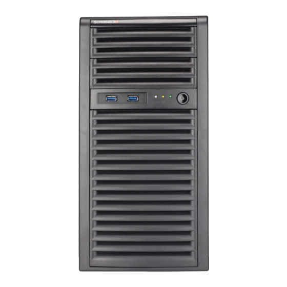
Chapter 1: Introduction 1.2 System Features Front View See the illustration below for the features included on the front of the system. Fixed Drives Control Panel Drive Cage Figure 1-1. System Front View System Front: Features Item Description Fixed Drives Supports two fixed 5.25"... -
Page 10: Control Panel
Chapter 1: Introduction Control Panel A power button and a UID button as well as status LEDs are located on the control panel at the front of the chassis. The locations and descriptions of these buttons and LEDs are provided below. See Chapter 4 for details on the control panel connections. -
Page 11: Rear View
Chapter 1: Introduction Rear View The illustration below shows the features included on the rear of the chassis. The power supply modules also have status LEDs (see Chapter 3 for details). Power Supply I/O Backplane PCI Slots Figure 1-3. System Rear View Chassis Rear Features Feature Description... - Page 12 Chapter 1: Introduction Figure 1-4. Rear I/O Panel Rear I/O Ports Item Description COM Port BMC LAN Port USB 2.0 Ports (USB0/USB1) USB 3.0 Ports (USB6/USB7) 1 GbE LAN Port (LAN1) 1 GbE LAN Port (LAN2) VGA Port...
-
Page 13: Motherboard Layout
Chapter 1: Introduction 1.3 Motherboard Layout Below is a layout of the X13SCL-F with jumper, connector and LED locations shown. See the table on the following pages for descriptions. For detailed descriptions, pinout information, and jumper settings, refer to Chapter 4. USB6/7 (3.0) COM1 JUIDB1... -
Page 14: Quick Reference Table
Chapter 1: Introduction Quick Reference Table Jumper Description Default Setting JBT1 CMOS Clear Open (Normal) JPG1 VGA Enable Pins 1–2 (Enabled) JPME2 ME Manufacturing Mode Pins 1–2 JVRM1 SMB DATA (to BMC) Pins 2–3 JVRM2 SMB CLOCK (to BMC) Pins 2–3 JVRM3 SMB DATA/CLOCK (to CHIP) Open... - Page 15 Chapter 1: Introduction Connector Description USB2/3, USB4/5 Front Accessible USB 2.0 Headers USB6/7 Back Panel USB 3.0 Ports USB8 Front Accessible USB 3.0 Type-A Header USB9/10 Front Accessible USB 3.0 Header VGA Port...
-
Page 16: System Architecture
Chapter 1: Introduction 1.4 System Architecture Power Supply Drive Bays DIMMs Drive Cage Processor Motherboard Figure 1-6. System Architecture System Main Components Feature Description Power Supply Single 400 W power supply Drive Bays Two 5.25" fixed drive bays 92 x 25 mm fan Single Intel®... - Page 17 Chapter 1: Introduction IMVP 8 6 PHASE for Vcore 95 W #B-1 #B-0 PCIe x8 PCIe Gen5 x8 #A-1 #PEG0–7 SLOT7 #A-0 PCIe x8 E-2400 CH-A PCIe Gen5 x8 DDR5 #PEG8–15 LGA1700 SLOT6 4400 MT/s ( in x16 ) CH-B PCIe x4 PCIe Gen4 x4 #PCIe0–3...
-
Page 18: Chapter 2 System Installation
Chapter 2: Workstation Installation Chapter 2 System Installation 2.1 Overview This chapter provides advice setting up your system. If your system is not already fully integrated with processors, system memory etc., refer to Chapter 4 for details on installing those specific components. Caution: Electrostatic Discharge (ESD) can damage electronic components. -
Page 19: Chapter 3 Maintenance And Component Installation
Chapter 3: Maintenance and Component Installation Chapter 3 Maintenance and Component Installation This chapter provides instructions on installing and replacing main system components. To prevent compatibility issues, only use components that match the specifications and/or part numbers given. Installation or replacement of most components require that power first be removed from the system. - Page 20 Chapter 3: Maintenance and Component Installation Top Cover Side Cover Chassis Cover Handle (B) Slide the latch A toward the handle B Latch R(A) Figure 3-1. Removing the Side Cover Note: All graphics in this manual are for illustrative purposes only. Your components may look different.
-
Page 21: Processor And Heatsink Installation
• When installing the processor and heatsink, ensure a torque driver set to the correct force is used for each screw. • Refer to the Supermicro website for updates on CPU support. Installing the LGA 1700 Processor Plastic protective cover... - Page 22 Chapter 3: Maintenance and Component Installation 1. Remove the plastic protective cover from the load plate. Lever lock 2. Gently push down the load lever to release and lift it, then lift the load plate to open it completely. 3. Use your thumb and your index finger to hold the CPU. Align the small triangle maker and notches on the CPU to the corresponding triangle maker and notches on the CPU Pin 1 CPU notch...
- Page 23 Chapter 3: Maintenance and Component Installation 5. With the CPU inside the socket, inspect all the corners to make sure it is properly installed. Lever lock 6. Close the load plate with the CPU inside the socket. Gently push the load lever down until it locks under the Lever Lock latch.
-
Page 24: Installing A Cpu Heatsink
Chapter 3: Maintenance and Component Installation Installing a CPU Heatsink Note 1: The installation described in this section is for reference only. The actual instal- lation steps may vary depending on the CPU heatsink model. Refer to the heatsink instructions for more details. Note 2: Graphic drawings included in this manual are for reference only. - Page 25 Chapter 3: Maintenance and Component Installation 3. Attach the backplate into the mounting holes around the CPU socket on the bottom side of the motherboard. Backplate bottom side Motherboard bottom side Mounting hole Motherboard Top side 4. Apply the proper amount of thermal grease on the CPU.
- Page 26 Chapter 3: Maintenance and Component Installation 5. Place the heatsink on top of the CPU so that the four mounting holes on the heatsink are aligned with those on the retention mechanism. 6. With a T30 bit torque driver set to a force of 6.0 in-lbf (0.678 n-m), gradually tighten the four screws to ensure even pressure.
-
Page 27: Removing The Heatsink
Chapter 3: Maintenance and Component Installation Removing the Heatsink Warning: We do not recommend that the CPU or heatsink be removed. However, if you do need to remove the heatsink, follow the instructions below to remove the heatsink and prevent damage done to the CPU or other components. 1. -
Page 28: Memory Support And Installation
Chapter 3: Maintenance and Component Installation 3.4 Memory Support and Installation Note: Check the Supermicro website for recommended memory modules. Exercise extreme care when installing or removing DIMM modules to prevent any damage. Memory Support The X13SCL-F supports up to 128 GB of unbuffered (UDIMM) DDR5 (288-pin) ECC memory (2-DIMM per channel) with speeds of up to 4400 MT/s in four memory slots. -
Page 29: General Guidelines For Optimizing Memory Performance
Chapter 3: Maintenance and Component Installation General Guidelines for Optimizing Memory Performance • The blue slots must be populated first. • It is recommended to use DDR5 memory of the same type, size, and speed. • Mixed DIMM speeds can be installed. However, all DIMMs will run at the speed of the slowest DIMM. -
Page 30: Dimm Installation
Chapter 3: Maintenance and Component Installation DIMM Installation 1. Insert the desired number of DIMMs into the memory slots based on the Recommended Memory Population Guide tables. Notches 2. Push the release tabs outwards on both ends of the DIMM slot to unlock it. 3. -
Page 31: Motherboard Battery
Chapter 3: Maintenance and Component Installation 3.5 Motherboard Battery The motherboard uses non-volatile memory to retain system information when system power is removed. This memory is powered by a lithium battery residing on the motherboard. Replacing the Battery Begin by removing power from the system as described in Section 3.1. -
Page 32: Pci Expansion Cards
Chapter 3: Maintenance and Component Installation 3.6 PCI Expansion Cards Four standard size PCI expansion (add-on) cards may be installed in the SYS-531R-I. Installing PCIe Cards Before installing a PCI expansion card, make sure it is supported by the card slot on the motherboard. -
Page 33: Storage Drives
Note that the SYS-531R-I must be powered down before drives can be installed or removed in the any of the system's drive bays. Note: Enterprise level storage drives are recommended for use in Supermicro chassis and workstations. For compatible storage drives, see https://www.supermicro.com/en/products/... - Page 34 Chapter 3: Maintenance and Component Installation Release Tab (A) Drive Cage (B) Figure 3-7. Rotating the Drive Cage Latch Figure 3-8. Installing a Drive into the Drive Cage...
-
Page 35: Optional Drive Bays
Chapter 3: Maintenance and Component Installation Optional Drive Bays The SYS-531R-I has two 5.25" drive bays at the top front of the chassis that support additional storage drives or optional devices such as a DVD-ROM. Installing an Optional Device 1. Begin by removing power from the system as described previously. 2. -
Page 36: System Cooling
Chapter 3: Maintenance and Component Installation 3.8 System Cooling The SYS-531R-I includes a super-quiet rear system fan that provides cooling for the chassis. No tools or screws are required to install the system fan. Under normal operation, the system fan and the power supply fan both run continuously. If the system fan fails, the SuperWorkstation must be powered down before replacing it. - Page 37 Chapter 3: Maintenance and Component Installation Figure 3-11. Removing the Front Bezel 2. Install the optional fan from the left side of the chassis, aligning the mounting holes of the fan grill with the mounting holes of the optional fan. 3.
-
Page 38: Power Supply
Chapter 3: Maintenance and Component Installation 3.9 Power Supply The SYS-531R-I includes a single 400W power supply. The power supply has the capability to automatically sense and operate with an input voltage of 100 or 240V AC. If it becomes necessary to replace the power supply, follow the instructions below.. Replacing the Power Supply 1. -
Page 39: Chapter 4 Motherboard Connections
Chapter 4: Motherboard Connections Chapter 4 Motherboard Connections This section describes the connections on the motherboard and provides pinout definitions. Note that depending on how the system is configured, not all connections are required. The LEDs on the motherboard are also described here. A motherboard layout indicating component locations may be found in Chapter Please review the Safety Precautions in Appendix A before installing or removing components. -
Page 40: Headers And Connectors
Chapter 4: Motherboard Connections 4.2 Headers and Connectors Chassis Intrusion A Chassis Intrusion header is located at JL1 on the motherboard. Attach the appropriate cable from the chassis to inform you of a chassis intrusion when the chassis is opened. Refer to the table below for pin definitions. - Page 41 These SATA ports support RAID 0, 1, 5, and 10. SATA ports provide serial-link signal connections, which are faster than the connections of Parallel ATA. Note: Supermicro SuperDOMs are yellow SATADOM connectors with power pins built in and do not require separate external power cables. These connectors are backwards compatible with non-Supermicro SATADOMS that require an external power supply.
-
Page 42: Front Control Panel
JF1 contains header pins for various buttons and indicators that are normally located on a control panel at the front of the chassis. These connectors are designed specifically for use with a Supermicro chassis. See the figure below for the descriptions of the front control panel buttons and LED indicators. - Page 43 Chapter 4: Motherboard Connections Power Fail LED The Power Fail LED connection is located on pins 5 and 6 of JF1. Refer to the table below for pin definitions. Power Fail LED Pin Definitions (JF1) Pin# Definition 3.3 V PWR Supply Fail Overheat/Fan Fail and UID LED Connect an LED cable to pins 7 and 8 of the Front Control Panel to use the Overheat/Fan Fail LED connections.
- Page 44 Chapter 4: Motherboard Connections Power LED The Power LED connection is located on pins 15 and 16 of JF1. Refer to the table below for pin definitions. Power LED Pin Definitions (JF1) Pin# Definition 3.3 V PWR LED NMI Button The non-maskable interrupt (NMI) button header is located on pins 19 and 20 of JF1.
-
Page 45: Ports
Chapter 4: Motherboard Connections 4.4 Ports Rear I/O Ports See the figure below for the locations and descriptions of the various I/O ports on the rear of the motherboard. Figure 4-2. Rear I/O Ports Rear I/O Ports Description Description COM1 USB6 (USB 3.0) Dedicated BMC LAN LAN1... - Page 46 Chapter 4: Motherboard Connections Universal Serial Bus (USB) Ports There are two USB 2.0 ports (USB0/1) and two USB 3.0 ports (USB6/7) located on the back I/O panel. The motherboard also has two front accessible USB 2.0 headers (USB2/3, USB4/5) and one front accessible USB 3.0 header (USB8/9).
- Page 47 Chapter 4: Motherboard Connections LAN Ports Two Gigabit Ethernet ports (LAN1, LAN2) are located on the back I/O panel. In addition, a dedicated BMC LAN is located above USB0/1. All of these ports accept RJ45 cables. Refer to the LED Indicator section for LAN LED information. LAN Ports BMC LAN Pin Definition...
-
Page 48: Jumpers
Chapter 4: Motherboard Connections 4.5 Jumpers Explanation of Jumpers To modify the operation of the motherboard, jumpers are used to choose between optional settings. Jumpers create shorts between two pins to change the function associated with it. Pin 1 is identified with a square solder pad on the printed circuit board. See the motherboard layout page for jumper locations. - Page 49 Chapter 4: Motherboard Connections ME Manufacturing Mode Close pins 2–3 of jumper JPME2 to bypass SPI flash security and force the system to operate in the manufacturing mode, which will allow the user to flash the system firmware from a host server for system setting modifications.
-
Page 50: Led Indicators
Chapter 4: Motherboard Connections 4.6 LED Indicators BMC Heartbeat LED A BMC Heartbeat LED is located at LEDM1 on the motherboard. When LEDM1 is blinking, the BMC is functioning normally. BMC Heartbeat LED Indicator LED Color Definition Green: Blinking BMC Normal LAN LEDs Two LAN ports (LAN1/2) are located on the I/O back panel. -
Page 51: Chapter 5 Software
BMC KVM console. 2. Go to the Supermicro web page for your motherboard and click on "Download the Latest Drivers and Utilities", select the proper driver, and copy it to a USB flash drive. - Page 52 Chapter 5: Software 4. During Windows Setup, continue to the dialog where you select the drives on which to install Windows. If the disk you want to use is not listed, click on “Load driver” link at the bottom left corner. Figure 5-2.
-
Page 53: Driver Installation
The Supermicro website contains drivers and utilities for your system at https://www. supermicro.com/wdl/. Some of these must be installed, such as the chipset driver. After accessing the website, go into the CDR_Images (in the parent directory of the above link) and locate the ISO file for your motherboard. Download this file to a USB flash or media drive. -
Page 54: Superdoctor ® 5
5.3 SuperDoctor ® The Supermicro SuperDoctor 5 is a program that functions in a command-line or web-based interface for Windows and Linux operating systems. The program monitors such system health information as CPU temperature, system voltages, system power consumption, fan speed, and provides alerts via email or Simple Network Management Protocol (SNMP). -
Page 55: Bmc
There are several BIOS settings that are related to BMC. For general documentation and information on BMC, visit our website at: www.supermicro.com/en/solutions/management-software/bmc-resources BMC ADMIN User Password For security, each system is assigned a unique default BMC password for the ADMIN user. -
Page 56: Chapter 6 Optional Components
Chapter 6: Optional Components Chapter 6 Optional Components This chapter lists optional system components. 6.1 Optional Parts List Optional Parts List Description Part Number DVD Kit CBL-0082L + CBL-SAST-0624 + DVM-TEAC-DVDRW24-HBT 2.5" to 3.5" HDD Tray Converter MCP-220-73102-0N Mobile Rack CSE-M14TQC 80 x 25 mm PWM Fan FAN-0113L4... -
Page 57: Chapter 7 Troubleshooting And Support
Chapter 7 Troubleshooting and Support 7.1 Information Resources Website A great deal of information is available on the Supermicro website, supermicro.com. Products Figure 7-1. Supermicro Website • Specifications for servers and other hardware are available by clicking the menu icon, then selecting the Products option. -
Page 58: Bmc Interface
Security Center for recent security notices Supermicro Phone and Addresses 7.2 BMC Interface The system supports a Baseboard Management Controller (BMC) interface. It provides remote access, monitoring and management. There are several BIOS settings related to the BMC. -
Page 59: Troubleshooting Procedures
Chapter 7: Troubleshooting and Support 7.3 Troubleshooting Procedures Use the following procedures to troubleshoot your system. If you have followed all of the procedures below and still need assistance, refer to the Technical Support Procedures Returning Merchandise for Service section(s) in this chapter. Power down the system before changing any non hot-swap hardware components. -
Page 60: No Video
• Memory: Make sure that the memory modules are supported. Refer to the product page on our website at www.supermicro.com. Test the modules using memtest86 or a similar utility. • Storage drives: Make sure that all drives work properly. Replace if necessary. - Page 61 Also check the Control panel Overheat LED. • Adequate power supply: Make sure that the power supply provides adequate power to the system. Make sure that all power connectors are connected. Refer to the Supermicro website for the minimum power requirements. •...
-
Page 62: Crash Dump Using The Bmc Dashboard
In the event of a processor internal error (IERR) that crashes your system, you may want to provide information to support staff. You can download a crash dump of status information using the BMC Dashboard. The BMC manual is available at https://www.supermicro.com/ manuals/other/BMC_IPMI_X13_H13.pdf. Check Error Log 1. -
Page 63: Cmos Clear
Chapter 7: Troubleshooting and Support 7.5 CMOS Clear JBT1 is used to clear CMOS, which will also clear any passwords. Instead of pins, this jumper consists of contact pads to prevent accidentally clearing the contents of CMOS. To Clear CMOS 1. -
Page 64: Where To Get Replacement Components
7.6 Where to Get Replacement Components If you need replacement parts for your system, to ensure the highest level of professional service and technical support, purchase exclusively from our Supermicro Authorized Distributors/System Integrators/Resellers. A list can be found at: http://www.supermicro.com. -
Page 65: Vendor Support Filing System
For issues related to Red Hat Enterprise Linux, since it is a subscription based OS, contact your account representative. 7.8 Feedback Supermicro values your feedback as we strive to improve our customer experience in all facets of our business. To provide feedback on our manuals, please email us at techwriterteam@... -
Page 66: Contacting Supermicro
San Jose, CA 95131 U.S.A. Tel: +1 (408) 503-8000 Fax: +1 (408) 503-8008 Email: marketing@supermicro.com (General Information) Sales-USA@supermicro.com (Sales Inquiries) Government_Sales-USA@supermicro.com (Gov. Sales Inquiries) support@supermicro.com (Technical Support) RMA@supermicro.com (RMA Support) Webmaster@supermicro.com (Webmaster) Website: www.supermicro.com Europe Address: Super Micro Computer B.V. -
Page 67: Appendix A Standardized Warning Statements For Ac Systems
Supermicro's Technical Support department for assistance. Only certified technicians should attempt to install or configure components. Read this appendix in its entirety before installing or configuring components in the Supermicro chassis. These warnings may also be found on our website at http://www.supermicro.com/about/... - Page 68 Appendix A: Warning Statements Warnung WICHTIGE SICHERHEITSHINWEISE Dieses Warnsymbol bedeutet Gefahr. Sie befinden sich in einer Situation, die zu Verletzungen führen kann. Machen Sie sich vor der Arbeit mit Geräten mit den Gefahren elektrischer Schaltungen und den üblichen Verfahren zur Vorbeugung vor Unfällen vertraut. Suchen Sie mit der am Ende jeder Warnung angegebenen Anweisungsnummer nach der jeweiligen Übersetzung in den übersetzten Sicherheitshinweisen, die zusammen mit diesem Gerät ausgeliefert wurden.
- Page 69 Appendix A: Warning Statements . ٌ ا ك ً ف حالة و ٌ يك أى تتسبب ف اصابة جسذ ة ٌ هذا الزهز ع ٌ خطز !تحذ ز قبل أى تعول عىل أي هعذات،يك عىل علن بالوخاطز ال ا ٌجوة عي الذوائز ٍ...
- Page 70 Appendix A: Warning Statements Warnung Vor dem Anschließen des Systems an die Stromquelle die Installationsanweisungen lesen. ¡Advertencia! Lea las instrucciones de instalación antes de conectar el sistema a la red de alimentación. Attention Avant de brancher le système sur la source d'alimentation, consulter les directives d'installation. .יש...
- Page 71 Appendix A: Warning Statements Warnung Dieses Produkt ist darauf angewiesen, dass im Gebäude ein Kurzschluss- bzw. Überstromschutz installiert ist. Stellen Sie sicher, dass der Nennwert der Schutzvorrichtung nicht mehr als: 250 V, 20 A beträgt. ¡Advertencia! Este equipo utiliza el sistema de protección contra cortocircuitos (o sobrecorrientes) del edificio.
- Page 72 Appendix A: Warning Statements Power Disconnection Warning Warning! The system must be disconnected from all sources of power and the power cord removed from the power supply module(s) before accessing the chassis interior to install or remove system components (except for hot-swap components). 電源切断の警告...
- Page 73 Appendix A: Warning Statements אזהרה מפני ניתוק חשמלי !אזהרה יש לנתק את המערכת מכל מקורות החשמל ויש להסיר את כבל החשמלי מהספק .לפני גישה לחלק הפנימי של המארז לצורך התקנת או הסרת רכיבים يجب فصم اننظاو من جميع مصادر انطاقت وإ ز انت سهك انكهرباء من وحدة امداد انطاقت...
- Page 74 Appendix A: Warning Statements Attention Seul le personnel autorisé et le personnel de maintenance qualifié doivent être autorisés à installer, remplacer ou entretenir cet équipement.. !אזהרה .יש לאפשר רק צוות מורשה ואנשי שירות מוסמכים להתקין, להחליף או לטפל בציוד זה .ينبغي...
- Page 75 Appendix A: Warning Statements Warnung Diese Einheit ist zur Installation in Bereichen mit beschränktem Zutritt vorgesehen. Der Zutritt zu derartigen Bereichen ist nur mit einem Spezialwerkzeug, Schloss und Schlüssel oder einer sonstigen Sicherheitsvorkehrung möglich. ¡Advertencia! Esta unidad ha sido diseñada para instalación en áreas de acceso restringido. Sólo puede obtenerse acceso a una de estas áreas mediante la utilización de una herramienta especial, cerradura con llave u otro medio de seguridad.
- Page 76 Appendix A: Warning Statements Battery Handling Warning! There is the danger of explosion if the battery is replaced incorrectly. Replace the battery only with the same or equivalent type recommended by the manufacturer. Dispose of used batteries according to the manufacturer's instructions 電池の取り扱い...
- Page 77 Appendix A: Warning Statements هناك خطر من انفجار يف حالة اسحبذال البطارية بطريقة غري صحيحة فعليل اسحبذال البطارية فقط بنفس النىع أو ما يعادلها مام أوصث به الرشمة املصنعة جخلص من البطاريات املسحعملة وفقا لحعليامت الرشمة الصانعة 경고! 배터리가 올바르게 교체되지 않으면 폭발의 위험이 있습니다. 기존 배터리와 동일하거나 제 조사에서...
- Page 78 Appendix A: Warning Statements ¡Advertencia! Puede que esta unidad tenga más de una conexión para fuentes de alimentación. Para cortar por completo el suministro de energía, deben desconectarse todas las conexiones. Attention Cette unité peut avoir plus d'une connexion d'alimentation. Pour supprimer toute tension et tout courant électrique de l'unité, toutes les connexions d'alimentation doivent être débranchées.
- Page 79 Appendix A: Warning Statements Backplane Voltage Warning! Hazardous voltage or energy is present on the backplane when the system is operating. Use caution when servicing. バックプレーンの電圧 システムの稼働中は危険な電圧または電力が、 バックプレーン上にかかっています。 修理する際には注意く ださい。 警告 当系统正在进行时,背板上有很危险的电压或能量,进行维修时务必小心。 警告 當系統正在進行時,背板上有危險的電壓或能量,進行維修時務必小心。 Warnung Wenn das System in Betrieb ist, treten auf der Rückwandplatine gefährliche Spannungen oder Energien auf.
- Page 80 Appendix A: Warning Statements هناك خطز مه التيار الكهزبايئ أوالطاقة املىجىدة عىل اللىحة عندما يكىن النظام يعمل كه حذ ر ا عند خدمة هذا الجهاس 경고! 시스템이 동작 중일 때 후면판 (Backplane)에는 위험한 전압이나 에너지가 발생 합니다. 서비스 작업 시 주의하십시오. Waarschuwing Een gevaarlijke spanning of energie is aanwezig op de backplane wanneer het systeem in gebruik is.
- Page 81 Appendix A: Warning Statements תיאום חוקי החשמל הארצי !אזהרה .התקנת הציוד חייבת להיות תואמת לחוקי החשמל המקומיים והארציים تركيب املعدات الكهربائية يجب أن ميتثل للقىاويه املحلية والىطىية املتعلقة بالكهرباء 경고! 현 지역 및 국가의 전기 규정에 따라 장비를 설치해야 합니다. Waarschuwing Bij installatie van de apparatuur moet worden voldaan aan de lokale en nationale elektriciteitsvoorschriften.
- Page 82 Appendix A: Warning Statements Attention La mise au rebut ou le recyclage de ce produit sont généralement soumis à des lois et/ou directives de respect de l'environnement. Renseignez-vous auprès de l'organisme compétent. סילוק המוצר !אזהרה .סילוק סופי של מוצר זה חייב להיות בהתאם להנחיות וחוקי המדינה التخلص...
- Page 83 Appendix A: Warning Statements Warnung Gefährlich Bewegende Teile. Von den bewegenden Lüfterblätter fern halten. Die Lüfter drehen sich u. U. noch, wenn die Lüfterbaugruppe aus dem Chassis genommen wird. Halten Sie Finger, Schraubendreher und andere Gegenstände von den Öffnungen des Lüftergehäuses entfernt.
- Page 84 Verbindungskabeln, Stromkabeln und/oder Adapater, die Ihre örtlichen Sicherheitsstandards einhalten. Der Gebrauch von anderen Kabeln und Adapter können Fehlfunktionen oder Feuer verursachen. Die Richtlinien untersagen das Nutzen von UL oder CAS zertifizierten Kabeln (mit UL/CSA gekennzeichnet), an Geräten oder Produkten die nicht mit Supermicro gekennzeichnet sind.
- Page 85 .قيرح وأ لطع يف ببستي دق ىرخأ تالوحمو تالباك يأ مادختسا .ميلسلا سباقلاو لصوملا مجح لبق نم ةدمتعملا تالباكلا مادختسا تادعملاو ةيئابرهكلا ةزهجألل ةمالسلا نوناق رظحيUL وأCSA ( ةمالع لمحت يتلاوUL/CSA) لبق نم ةددحملاو ةينعملا تاجتنملا ريغ ىرخأ تادعم يأ عمSupermicro.
- Page 86 사항을 준수하여 제공되거나 지정된 연결 혹은 구매 케이블, 전원 케이블 및 AC 어댑터를 사용하십시오. 다른 케이블이나 어댑터를 사용하면 오작동이나 화재가 발생할 수 있습니다. 전기 용품 안전법은 UL 또는 CSA 인증 케이블 (코드에 UL / CSA가 표시된 케이블)을 Supermicro 가 지정한 제품 이외의 전기 장치에 사용하는 것을 금지합니다. Stroomkabel en AC-Adapter...
-
Page 87: Appendix B System Specifications
Appendix B: System Specifications Appendix B System Specifications Processor Support Single Intel Xeon E-2400 and 12th Gen Pentium (V0 LGA 1700) processors with a thermal design power (TDP) of up to 95 W and up to eight cores Note: Please refer to the motherboard specifications pages on our website for updates to supported processors. Chipset Intel C262 BIOS... - Page 88 Appendix B: System Specifications Operating Environment Operating Temperature: 10º to 35º C (50º to 95º F)* Non-operating Temperature: -30º to 60º C (-22º to 140º F) Operating Relative Humidity: 8% to 80% (non-condensing) Non-operating Relative Humidity: 8% to 90% (non-condensing) Regulatory Compliance FCC, ICES, CE, UKCA, VCCI, RCM, NRTL, CB Applied Directives, Standards...
Need help?
Do you have a question about the SuperWorkstation SYS-531R-I and is the answer not in the manual?
Questions and answers