Sign In
Upload
Manuals
Brands
Texas Instruments Manuals
Motherboard
DS90UB95x-Q1EVM Series
Texas Instruments DS90UB95x-Q1EVM Series Manuals
Manuals and User Guides for Texas Instruments DS90UB95x-Q1EVM Series. We have
2
Texas Instruments DS90UB95x-Q1EVM Series manuals available for free PDF download: User Manual
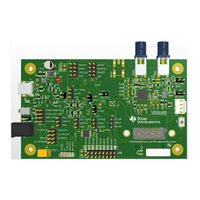
Texas Instruments DS90UB95x-Q1EVM Series User Manual (66 pages)
Brand:
Texas Instruments
| Category:
Motherboard
| Size: 6 MB
Table of Contents
Table of Contents
1
1 Trademarks
4
2 Introduction
4
Figure 2-1. Ds90Ub95X-Q1EVM
4
3 Quick Start Guide
5
System Requirements
5
Included Components
5
Additional Required Components
5
Applications Diagram
5
Major Components of Ds90Ub95X-Q1EVM
5
Figure 3-1. Applications Diagram
5
Ds90Ub95X-Q1EVM Setup
6
4 Ds90Ub95X-Q1EVM Board Configuration
6
Default Configuration
6
Figure 4-1. Ds90Ub95X-Q1EVM with Jumpers
6
Power Supply
7
Power-Over-Coax Interface
7
Figure 4-2. Power-Over-Coax Network for Use with DS90UB953
7
Table 4-1. Power Supply
7
MIPI CSI-2 Output Signals
8
Figure 4-3. Power-Over-Coax Network for Use with DS90UB933
8
Table 4-2. Power-Over-Coax Power Supply Feed Configuration
8
Table 4-3. MIPI CSI-2 Output Signals - J5 and J6 Pinout
9
FPD-Link III Signals
10
I 2 C Interface
10
Table 4-4. FPD-Link III Signals
10
Table 4-5. IDX I 2 C Device Address Select - J23
10
Table 4-6. I 2 C Interface Header - J25
10
Control Interface
11
Table 4-7. VDDIO Interface Header - J16
11
Table 4-8. GPIO Interface Header - J22
11
Table 4-9. CMLOUT Output Signals
11
Table 4-10. FPD-Link III Mode Control-J15
11
Table 4-11. Device Mode Control - J11
11
5 Enable and Reset
12
6 Use with DS90UB936-Q1
12
Table 4-12. Leds
12
7 Typical Connection and Test Equipment
13
8 Termination Device
13
9 Typical Test Setup
13
Figure 9-1. Typical Test Setup for Evaluation
13
10 Equipment References
14
11 Cable References
14
12 Software for Ds90Ub95Xq1-EVM Evaluation - Analog Launchpad (ALP) Software Setup
15
System Requirements
15
Download Contents
15
Installation of the ALP Software
15
Startup - First Launch
16
Figure 12-1. Launching ALP Splash Screen
16
Figure 12-2. Initial ALP Screen
16
Figure 12-3. Select Usb2Any/Aardvark Setup to Change Profile
17
Figure 12-4. ALP Profiles Dialog
18
Figure 12-5. ALP Profiles Dialog (Continued)
19
13 Using ALP and Ds90Ub95X Profile
20
Information Tab
20
Figure 13-1. ALP Information Tab
20
Registers Tab
21
Figure 13-2. ALP Registers Tab
21
Registers Tab - Address 0X00 Expanded
22
Port Specific Registers
22
Saving and Loading Register Settings
22
Figure 13-3. ALP Device ID Expanded
22
Figure 13-4. Save Register Settings Step 1
23
Figure 13-5. Save Register Settings Step 2
23
Figure 13-6. Save Register Settings Step 3
24
Figure 13-7. Load Register Settings Step 1
24
Figure 13-8. Load Register Settings Step 2
25
Figure 13-9. Load Register Settings Step 3
25
Scripting Tab
26
Figure 13-10. ALP Scripting Tab
26
Figure 13-11. Pre-Defined Scripts
27
Figure 13-12. Custom Button Creation Step 1
27
Example Functions
28
Figure 13-13. Custom Button Creation Step 2
28
GPIO Tab
30
Figure 13-14. GPIO Tab
30
Forwarding Tab
31
Figure 13-15. Forwarding Tab
31
CSI Registers Tab
32
Figure 13-16. CSI Registers Tab
32
Remote Registers Tab
33
Figure 13-17. Remote Registers Tab
33
14 Troubleshooting ALP Software
34
ALP Does Not Detect the EVM
34
Figure 14-1. ALP no Devices Error
34
Figure 14-2. Windows 7, ALP USB2ANY Driver
34
USB2ANY Firmware Issues
35
Figure 14-3. ALP in Demo Mode
35
Figure 14-4. ALP Preferences Menu
35
Figure 14-5. USB2ANY Firmware Update Notice
36
Figure 14-6. USB2ANY Firmware Update Procedure
36
15 Ds90Ub95X-Q1EVM PCB Schematics, Layout and Bill of Materials - Ds90Ub95X-Q1EVM Schematic
37
Figure 15-1. Ds90Ub95X-Q1EVM Block Diagram
37
Figure 15-2. Ds90Ub95X-Q1EVM Main Circuit
38
Figure 15-3. Ds90Ub95X-Q1EVM CSI-2 Connectors
39
Figure 15-4. Ds90Ub95X-Q1EVM Poc Circuits
40
16 Ds90Ub95X-Q1 EVM PCB Layout
45
17 Ds90Ub95Xq1-EVM Bill of Materials
55
Table 17-1. Ds90Ub95X-Q1EVM BOM
55
18 Revision History
60
Evm
65
Advertisement
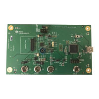
Texas Instruments DS90UB95x-Q1EVM Series User Manual (59 pages)
Serializer Evaluation Module
Brand:
Texas Instruments
| Category:
Motherboard
| Size: 4 MB
Table of Contents
Table of Contents
1
Introduction
3
Figure 1-1. Ds90Ub95X-Q1EVM Top View
3
Quick Start Guide
4
Figure 2-1. Typical Application Block Diagram Using DS90UB953-Q1 and DS90UB954-Q1
4
Figure 2-2. Ds90Ub95X-Q1EVM Major Components
5
Figure 2-3. Ds90Ub95X-Q1EVM with Installed Jumpers
5
Figure 2-4. DS90UB954-Q1EVM (or Variant) with Jumpers Highlighted
6
Troubleshooting
7
Figure 3-1. USB2ANY
7
Alp
7
Figure 3-2. I2C Pinout of USB2ANY Connector
8
Figure 3-3. Launching ALP
10
Figure 3-4. Initial ALP Screen
10
Figure 3-5. Follow-Up Screen
11
Figure 3-6. ALP Information Tab
12
Figure 3-7. ALP Registers Tab
13
Figure 3-8. ALP Device ID Selected
14
Figure 3-9. ALP Device ID Expanded
15
Figure 3-11. ALP Scripting Tab
16
Figure 3-12. Pre-Defined Scripts
17
Figure 3-13. Custom Button Creation Step 1
18
Figure 3-14. Custom Button Creation Step 2
18
Figure 3-15. ALP Scripting Tab
21
Figure 3-16. USB2ANY Setup
22
Figure 3-17. Remove Incorrect Profile
22
Figure 3-18. Add Correct Profile
23
Figure 3-19. Finish Setup
23
Figure 3-20. ALP no Devices Error
24
Figure 3-21. Windows 7, ALP USB2ANY Driver
24
Figure 3-22. ALP in Demo Mode
25
Figure 3-23. ALP Preferences Menu
25
Figure 3-24. Error that States One Instance of this Application Can be Active in ALP
26
Figure 3-25. Ending Maingui.exe in Task Manager
26
Figure 3-26. Error that States that USB2ANY Firmware Must be
27
Figure 3-27. USB2ANY Firmware Loader Program Dialog
28
Figure 3-28. USB2ANY Without Enclosure
29
Figure 3-29. USB2ANY with Enclosure
29
Figure 3-30. Verifying Ds90Ub95X Register
30
Figure 3-31. Window for Setting up Scripts in ALP
30
Table 3-1. Equipment
31
Figure 3-32. DS90UB954-Q1EVM (or Variant) with Highlighted Jumpers
33
Figure 3-33. Ds90Ub95X-Q1EVM with Installed Jumpers
34
Figure 3-34. Test Setup
35
Figure 3-35. Setting up Device Profiles in ALP
36
Figure 3-36. Navigating to DS90UB954 (or Variant) Scripting Tab in ALP
36
Figure 3-37. Reading I2C Device ID Within the Register Tab
37
Figure 3-38. Verifying Pass and Lock for DS90UB954 (or Variant) in ALP
37
Figure 3-39. Verifying Camera Initialization in ALP
38
Bill of Materials
39
Table 4-1. Bill of Materials
39
PCB Schematics
43
Figure 5-1. Ds90Ub95X-Q1EVM Schematic 1
43
Figure 5-2. Ds90Ub95X-Q1EVM Schematic 2
44
Figure 5-3. Ds90Ub95X-Q1EVM Schematic 3
45
Figure 5-4. Ds90Ub95X-Q1EVM Schematic 4
46
Board Layout
47
Figure 6-1. Top Layer PCB Layout
47
Figure 6-2. Top Overlay
47
Figure 6-3. Top Paste
48
Figure 6-4. Top Solder
48
Figure 6-5. Signal Layer 1
49
Figure 6-6. Signal Layer 2
49
Figure 6-7. Signal Layer 3
50
Figure 6-8. Signal Layer 4
50
Figure 6-9. Bottom Layer PCB Layout
51
Figure 6-10. Bottom Overlay
51
Figure 6-11. Bottom Paste
52
Figure 6-12. Bottom Solder
52
Related Documentation
53
Revision History
53
Updated
53
Advertisement
Related Products
Texas Instruments DS90UB954-Q1EVM
Texas Instruments DS90UB95 Q1EVM Series
Texas Instruments DS90UB953-Q1
Texas Instruments DS90UB95x-Q1
Texas Instruments DS90UB95 Q1 Series
Texas Instruments DS90UB960-Q1
Texas Instruments DS90UB925QSEVB
Texas Instruments DS90UB96X-Q1EVM
Texas Instruments DS90UB913A-CXEVM
Texas Instruments DS90UB914A-CXEVM
Texas Instruments Categories
Motherboard
Control Unit
Microcontrollers
Computer Hardware
Calculator
More Texas Instruments Manuals
Login
Sign In
OR
Sign in with Facebook
Sign in with Google
Upload manual
Upload from disk
Upload from URL