Table of Contents
Advertisement
Quick Links
SERVICE MANUAL
INDOOR UNIT
<DIGITAL INVERTER>
RAV-SM304SDT-E
RAV-SM404SDT-E
RAV-SM454SDT-E
RAV-SM564SDT-E
OUTDOOR UNIT
<SUPER DIGITAL INVERTER>
RAV-SP404AT-E
RAV-SP404ATZ-E
RAV-SP404ATZG-E RAV-SP454ATZG-E
RAV-SP564AT-E
RAV-SP564ATZ-E
RAV-SP564ATZG-E RAV-SP804ATZG-E
R410A
Revision 1 : Jan., 2012
Revision 2 : Oct., 2014
SPLIT TYPE
RAV-SM304SDT-TR
RAV-SP454AT-E
RAV-SP454ATZ-E
RAV-SP804AT-E
RAV-SP804ATZ-E
PRINTED IN JAPAN, Jan., 2009 ToMo
FILE NO. A08-007
Advertisement
Table of Contents
Troubleshooting

Related Manuals for Toshiba RAV-SM304SDT-TR


Summary of Contents for Toshiba RAV-SM304SDT-TR
- Page 1 FILE NO. A08-007 Revision 1 : Jan., 2012 Revision 2 : Oct., 2014 SERVICE MANUAL SPLIT TYPE INDOOR UNIT <DIGITAL INVERTER> RAV-SM304SDT-E RAV-SM304SDT-TR RAV-SM404SDT-E RAV-SM454SDT-E RAV-SM564SDT-E OUTDOOR UNIT <SUPER DIGITAL INVERTER> RAV-SP404AT-E RAV-SP454AT-E RAV-SP404ATZ-E RAV-SP454ATZ-E RAV-SP404ATZG-E RAV-SP454ATZG-E RAV-SP564AT-E RAV-SP804AT-E RAV-SP564ATZ-E...
-
Page 2: Table Of Contents
Adoption of New Refrigerant This Air Conditioner is a new type which adopts a new refrigerant HFC (R410A) instead of the conventional refrigerant R22 in order to prevent destruction of the ozone layer. WARNING Cleaning of the air filter and other parts of the air filter involves dangerous work in high places, so be sure to have a service person do it. - Page 3 7. REFRIGERANT R410A ................39 7-1. Safety During Installation/Servicing ............... 39 7-2. Refrigerant Piping Installation ............... 39 7-3. Tools ........................43 7-4. Recharging of Refrigerant................43 7-5. Brazing of Pipes ....................44 7-6. Instructions for Re-use Piping of R22 or R407C ..........46 8.
- Page 4 Toshiba Carrier Corporation or, alternatively, he or she has been instructed in such matters by an individual or individuals who have been trained and is thus thoroughly acquainted with the knowledge related to this work.
- Page 5 Definition of Protective Gear When the air conditioner is to be transported, installed, maintained, repaired or removed, wear protective gloves and ‘safety’ work clothing. In addition to such normal protective gear, wear the protective gear described below when undertaking the special work detailed in the table below.
- Page 6 Warning Indications on the Air Conditioner Unit [Confirmation of warning label on the main unit] Confirm that labels are indicated on the specified positions If removing the label during parts replace, stick it as the original. Warning indication Description WARNING WARNING ELECTRICAL SHOCK HAZARD ELECTRICAL SHOCK HAZARD...
-
Page 7: Precaution For Safety
Precaution for Safety The manufacturer shall not assume any liability for the damage caused by not observing the description of this manual. WARNING Before starting to repair the air conditioner, read carefully through the Service Manual, and repair the air conditioner by following its instructions. Only qualified service person (∗1) is allowed to repair the air conditioner. - Page 8 Even if the circuit breaker has been set to the OFF position before the service panel is removed and the electrical parts are repaired, you will still risk receiving an electric shock. For this reason, short-circuit the high-voltage capacitor terminals to discharge the voltage before proceeding with the repair work.
- Page 9 The refrigerant used by this air conditioner is the R410A. Check the used refrigerant name and use tools and materials of the parts which match with it. For the products which use R410A refrigerant, the refrigerant name is indicated at a position on the outdoor unit where is easy to see.
- Page 10 Once the repair work has been completed, check for refrigerant leaks, and check the insulation resistance and water drainage. Then perform a trial run to check that the air conditioner is running properly. After repair work has finished, check there is no trouble. If check is not executed, a fire, electric shock or injury may be caused.
- Page 11 Toshiba Carrier Corporation 336 Tadehara, Fuji-shi, Shizuoka-ken 416-8521 JAPAN Authorized Nick Ball Representative/TCF holder: Toshiba EMEA Engineering Director Toshiba Carrier UK Ltd. Porsham Close, Belliver Industrial Estate, PLYMOUTH, Devon, PL6 7DB. United Kingdom Hereby declares that the machinery described below:...
- Page 12 Model Main unit (Ceiling panel) Cooling Heating ∗ ∗ RAV-SM304SDT-E ∗ ∗ RAV-SM404SDT-E ∗ ∗ RAV-SM454SDT-E ∗ ∗ RAV-SM564SDT-E ∗ ∗ RAV-SM304SDT-TR ∗ ∗ RAV-SP404AT-E ∗ ∗ RAV-SP404ATZ-E ∗ ∗ RAV-SP404ATZG-E ∗ ∗ RAV-SP454AT-E ∗ ∗ RAV-SP454ATZ-E ∗ ∗ RAV-SP454ATZG-E ∗...
- Page 13 • New Refrigerant (R410A) This air conditioner adopts a new HFC type refrigerant (R410A) which does not deplete the ozone layer. 1. Safety Caution Concerned to New Refrigerant The pressure of R410A is high 1.6 times of that of the former refrigerant (R22). Accompanied with change of refrigerant, the refrigerating oil has been also changed.
- Page 14 4. Tools 1. Required Tools for R410A Mixing of different types of oil may cause a trouble such as generation of sludge, clogging of capillary, etc. Accordingly, the tools to be used are classified into the following three types. 1) Tools exclusive for R410A (Those which cannot be used for conventional refrigerant (R22)) 2) Tools exclusive for R410A, but can be also used for conventional refrigerant (R22) 3) Tools commonly used for R410A and for conventional refrigerant (R22) The table below shows the tools exclusive for R410A and their interchangeability.
-
Page 15: Specifications
1. SPECIFICATIONS 1-1. Indoor Unit 1-1-1. 4-Way Air Discharge Cassette Type <Single type> Indoor unit RAV-SM564UT-E RAV-SM804UT-E Model Outdoor unit RAV-SP564AT(Z)(ZG)-E RAV-SP804AT(Z)(ZG)-E Cooling capacity (kW) Heating capacity (kW) Power supply 1 phase 230V (220 – 240V) 50Hz Running current 6.82 – 6.25 8.72 –... - Page 16 1-1-2. Concealed Duct Type <Single type> Indoor unit RAV-SM562BT-E RAV-SM802BT-E Model Outdoor unit RAV-SP564AT(Z)(ZG)-E RAV-SP804AT(Z)(ZG)-E Cooling capacity (kW) Heating capacity (kW) Power supply 1 phase 230V (220 – 240V) 50Hz Running current 7.24 – 6.63 10.36 – 9.49 Power consumption (kW) 1.56 2.21...
- Page 17 1-1-3. Under Ceiling Type <Single type> Indoor unit RAV-SM562CT-E RAV-SM802CT-E Model Outdoor unit RAV-SP564AT(Z)(ZG)-E RAV-SP804AT(Z)(ZG)-E Cooling capacity (kW) Heating capacity (kW) Power supply 1 phase 230V (220 – 240V) 50Hz Running current 7.24 – 6.63 10.36 – 9.49 Power consumption (kW) 1.56 2.21...
- Page 18 1-1-4. High Wall Type <Single type> Indoor unit RAV-SM562KRT-E RAV-SM802KRT-E Model Outdoor unit RAV-SP564AT(Z)(ZG)-E RAV-SP804AT(Z)(ZG)-E Cooling capacity (kW) Heating capacity (kW) Power supply 1 phase 230V (220 – 240V) 50Hz Running current 7.24 – 6.63 11.25 – 10.31 Power consumption (kW) 1.56 2.40...
- Page 19 1-1-5. Compact 4-Way Air Discharge Cassette Type (600 × 600) <Single type> Indoor unit RAV-SM 402MUT-E 452MUT-E 562MUT-E Model Outdoor unit RAV-SP 404AT(Z)(ZG)-E 454AT(Z)(ZG)-E 564AT(Z)(ZG)-E Cooling capacity (kW) Heating capacity (kW) Power supply 1 phase 230V (220 – 240V) 50Hz Running current 5.05 –...
- Page 20 <Twin type> Indoor unit 1 RAV-SM402MUT-E Model Indoor unit 2 RAV-SM402MUT-E Outdoor unit RAV-SP804AT(Z)(ZG)-E Cooling capacity (kW) Heating capacity (kW) Indoor unit Power supply 1 phase 230V (220 – 240V) 50Hz Running current 10.36 – 9.49 Power consumption (kW) 2.21 Cooling Power factor 3.21...
- Page 21 1-1-6. Slim Duct Type <Single type> Indoor unit RAV-SM 404SDT-E 454SDT-E 564SDT-E Model Outdoor unit RAV-SP 404AT(Z)(ZG)-E 454AT(Z)(ZG)-E 564AT(Z)(ZG)-E Cooling capacity (kW) Heating capacity (kW) Power supply 1 phase 230V (220 – 240V) 50Hz Running current 5.20 – 4.77 5.87 – 5.38 7.24 –...
- Page 22 <Twin type> Indoor unit 1 RAV-SM404SDT-E Model Indoor unit 2 RAV-SM404SDT-E Outdoor unit RAV-SP804AT(Z)(ZG)-E Cooling capacity (kW) Heating capacity (kW) Indoor unit Power supply 1 phase 230V (220 – 240V) 50Hz Running current 10.36 – 9.49 Power consumption (kW) 2.21 Cooling Power factor 3.21...
-
Page 23: Outdoor Unit
1-2. Outdoor Unit <Super Digital Inverter> Model name Outdoor unit RAV-SP 404AT(Z)(ZG)-E 454AT(Z)(ZG)-E 564AT(Z)(ZG)-E 804AT(Z)(ZG)-E 1 phase 230V (220 – 240V) 50Hz Power supply (Power exclusive to outdoor is required.) Type Hermetic compressor Compressor Motor (kW) Pole Refrigerant charged (kg) Refrigerant control Pulse motor valve Standard length... -
Page 24: Operation Characteristic Curve
1-3. Operation Characteristic Curve • Operation characteristic curve <Super Digital Inverter> RAV-SP564AT-E, RAV-SP564ATZ-E, RAV-SP564ATZG-E <Cooling> <Heating> RAV-SM562BT, CT, KRT, MUT-E, RAV-SM562BT, CT, KRT, MUT-E, RAV-SM562BT, CT, KRT, MUT-E, RAV-SM562BT, CT, KRT, MUT-E, RAV-SM564SDT-E RAV-SM564SDT-E RAV-SM564SDT-E RAV-SM564SDT-E RAV-SM564UT-E RAV-SM564UT-E RAV-SM564UT-E RAV-SM564UT-E •... - Page 25 RAV-SP404AT-E, RAV-SP404ATZ-E, RAV-SP404ATZG-E RAV-SP454AT-E, RAV-SP454ATZ-E, RAV-SP454ATZG-E <Cooling> <Heating> SP45 SP45 SP45 SP45 SP40 SP40 SP40 SP40 • Conditions • Conditions Indoor : DB27˚C/WB19˚C Indoor : DB20˚C Outdoor : DB35˚C Outdoor : DB7˚C/WB6˚C Air flow : High Air flow : High Pipe length : 7.5m Pipe length : 7.5m 230V...
-
Page 26: Construction Views (External Views)
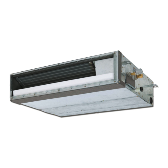
2. CONSTRUCTION VIEWS (EXTERNAL VIEWS) 2-1. Indoor Unit RAV-SM304SDT-E, RAV-SM304SDT-TR, RAV-SM404SDT-E, RAV-SM454SDT-E, RAV-SM564SDT-E 803 (inside) Refrigerant piping Air filter Fresh air inlet Drain-up port (knock-out hole) Hung-up plate – 26 –... -
Page 27: Outdoor Unit
2-2. Outdoor Unit RAV-SP404AT(Z)(ZG)-E, RAV-SP454AT(Z)(ZG)-E, RAV-SP564AT(Z)(ZG)-E Drain hole Drain hole (Ø25) (2-Ø20 × 88 long hole) 2-Ø11-14 U-shape hole A legs (For Ø8-Ø10 anchor bolts) Connecting pipe port (Gas flare side: Ø12.7) Connecting pipe port (Liquid flare side: Ø6.4) 8-Ø6 hole (For fixing outdoor unit) B legs 2-Ø11 ×... - Page 28 RAV-SP804AT(Z)(ZG)-E – 28 –...
- Page 29 RAV-TWP30E2, RAV-TWP50E2 (Simultaneous Twin) Inner diameter Ø C Inner Inner diameter Ø D diameter Ø D Model (RBC-) Liquid side Ø9.5 Ø6.4 TWP30E2 Gas side Ø15.9 Ø12.7 Liquid side Ø9.5 Ø9.5 TWP50E2 Gas side Ø15.9 Ø15.9 – 29 –...
-
Page 30: Systematic Refrigerating Cycle Diagram
3. SYSTEMATIC REFRIGERATING CYCLE DIAGRAM 3-1. Indoor Unit • Single type (Combination of 1 indoor unit and 1 outdoor unit) (Indoor unit) Distributor (Strainer incorporated) TCJ sensor Strainer Air heat exchanger TC sensor Heating Cooling Refrigerant pipe Refrigerant pipe at liquid side at gas side (Outer dia : ØB) (Outer dia : ØA) -
Page 31: Outdoor Unit
3-2. Outdoor Unit RAV-SP404AT-E, RAV-SP404ATZ-E, RAV-SP404ATZG-E RAV-SP454AT-E, RAV-SP454ATZ-E, RAV-SP454ATZG-E Packed valve Packed valve Outer dia. ØA Outer dia. ØB TS sensor (Pulse Motor Valve) (CAM-B30YGTF-2) TO sensor 2-step muffler Ø19.05 × 200L TD sensor Strainer 4-way valve (STF-0108Z) sensor Heat exchanger Muffler Ø8 ripple, 2 rows, Ø19 ×... - Page 32 RAV-SP564AT-E, RAV-SP564ATZ-E, RAV-SP564ATZG-E TO sensor (Pulse Motor Valve) (CAM-B30YGTF-2) sensor sensor TE sensor Muffler 4-way valve Ø31.75 × 200L (STF-0213Z) Muffler Heat exchanger Ø19.05 × 160L Ø8 ripple, 2 rows, 20 stages FP1.3, flat fin Strainer Distributor Accumulator Refrigerant pipe (1L) at liquid side Ø6.4 Rotary compressor...
- Page 33 RAV-SP804AT-E, RAV-SP804ATZ-E, RAV-SP804ATZG-E TS sensor TO sensor TL sensor (Pulse Motor Valve) (CAM-B30YGTF-2) Ø2 × Ø3 × 600L sensor Ø2 × Ø3 × 550L Accumulator Strainer Sub-ass’y Ø2 × Ø3 × 450L TE sensor 4-way valve (STF-0218G) Ø2 × Ø3 ×...
-
Page 34: Fan Characteristics
4. FAN CHARACTERISTICS 4-1. Slim Duct (Filter Attached) SM30 type SM40, 45 type Standard air volume : 660 m³/h Standard air volume : 690 m³/h Upper limit of external static pressure (50Pa) High (50Pa) High (50Pa) Upper limit of external static pressure (50Pa) High Lower limit of... -
Page 35: Wiring Diagram
5. WIRING DIAGRAM 5-1. Indoor Unit 5-1-1. Slim Duct Type RAV-SM304SDT-E, RAV-SM304SDT-TR, RAV-SM404SDT-E, RAV-SM454SDT-E, RAV-SM564SDT-E CN333 (WHI) 1 2 3 6 7 8 9 10 11 12 13 14 15 16 17 18 19 20 1 2 3 CN510 CN504... -
Page 36: Outdoor Unit
5-2. Outdoor Unit RAV-SP404AT-E, RAV-SP404ATZ-E, RAV-SP404ATZG-E RAV-SP454AT-E, RAV-SP454ATZ-E, RAV-SP454ATZG-E RAV-SP564AT-E, RAV-SP564ATZ-E, RAV-SP564ATZG-E – 36 –... - Page 37 RAV-SP804AT-E, RAV-SP804ATZ-E, RAV-SP804ATZG-E <MCC-1571> Reactor Reactor (RED) (WHI) (BLK) (GRY) (GRY) (WHI) (WHI) P04 P05 P06 P07 CN200 CN201 CN202 CN300 (WHI) SW804 SW801 SW800 CN609 (BLU) CN610 (YEL) Control P.C. Board MCC-1571 SW803 CN604 (WHI) CN603 (WHI) Fuse, F01 T25A, 250V~ CN602 (BLK)
-
Page 38: Specifications Of Electrical Parts
6. SPECIFICATIONS OF ELECTRICAL PARTS 6-1. Indoor Unit RAV-SM304SDT-E, RAV-SM304SDT-TR, RAV-SM404SDT-E, RAV-SM454SDT-E, RAV-SM564SDT-E Parts name Type Specifications Fan motor SWF-280-60-3 — Drain pump motor MDP-1401 — Float switch FS-0218-102 — TA sensor Lead wire length : 328mm 10 kΩ at 25°C TC sensor Ø6 size lead wire length : 1200 mm Vinyl tube (Black) -
Page 39: Refrigerant R410A
7. REFRIGERANT R410A This air conditioner adopts the new refrigerant HFC 6. When an air conditioning system charged with a (R410A) which does not damage the ozone layer. large volume of refrigerant is installed in a small room, it is necessary to exercise care so that, The working pressure of the new refrigerant R410A even when refrigerant leaks, its concentration is 1.6 times higher than conventional refrigerant... - Page 40 Table 7-2-1 Thicknesses of annealed copper pipes Thickness (mm) Nominal diameter Outer diameter (mm) R410A 0.80 0.80 0.80 0.80 12.7 0.80 0.80 15.9 1.00 1.00 1. Joints For copper pipes, flare joints or socket joints are used. Prior to use, be sure to remove all contaminants. a) Flare Joints Flare joints used to connect the copper pipes cannot be used for pipings whose outer diameter exceeds 20 mm.
- Page 41 c) Insertion of Flare Nut d) Flare Processing Make certain that a clamp bar and copper pipe have been cleaned. By means of the clamp bar, perform the flare processing correctly. Use either a flare tool for R410A or conventional flare tool. ØD Flare processing dimensions differ according to the type of flare tool.
- Page 42 Fig. 7-2-2 Relations between flare nut and flare seal surface 2. Flare Connecting Procedures and Precautions a) Make sure that the flare and union portions do not have any scar or dust, etc. b) Correctly align the processed flare surface with the union axis. c) Tighten the flare with designated torque by means of a torque wrench.
-
Page 43: Tools
7-3. Tools 7-3-1. Required Tools Refer to the “4. Tools” (Page 14) 7-4. Recharging of Refrigerant When it is necessary to recharge refrigerant, charge the specified amount of new refrigerant according to the following steps. Recover the refrigerant, and check no refrigerant remains in the equipment. -
Page 44: Brazing Of Pipes
1) Be sure to make setting so that liquid can be charged. 2) When using a cylinder equipped with a siphon, liquid can be charged without turning it upside down. It is necessary for charging refrigerant under condition of liquid because R410A is mixed type of refrigerant. Accordingly, when charging refrigerant from the refrigerant cylinder to the equipment, charge it turning the cylinder upside down if cylinder is not equipped with siphon. - Page 45 2. Characteristics required for flux 7-5-3. Brazing • Activated temperature of flux coincides with As brazing work requires sophisticated techniques, the brazing temperature. experiences based upon a theoretical knowledge, it must be performed by a person qualified. • Due to a wide effective temperature range, flux is hard to carbonize.
-
Page 46: Instructions For Re-Use Piping Of R22 Or R407C
Operation System • In the concurrent twin system, when TOSHIBA- ∗ Pipe diameter and thickness (mm) specified branching pipe is used, it can be reused. - Page 47 7-6-5. Final Installation Checks Is there no scratch or dent on the existing pipes? Existing pipe: NO * Use a new pipes. Is it possible to operate the existing air conditioner? ∗ After the existing air conditioner operated in cooling mode for approx.
- Page 48 7-6-6. Handling of Existing Pipe RAV-SP804AT-E • To use an existing Ø19.1 mm pipe, set bit 3 of When using the existing pipe, carefully check it for SW802 (switch for existing pipe) on the P.C. board the following: of the outdoor unit to ON. •...
-
Page 49: Indoor Control Circuit (Slim Duct Type)
8. INDOOR CONTROL CIRCUIT (Slim Duct Type) 8-1. Indoor Controller Block Diagram 8-1-1. Connection of Wired Remote Controller Wired remote controller (Max. 2 units) Weekly timer Display LCD Function setup Display LCD LCD driver Display LED Key switch Function setup Key switch DC5V Remote controller... - Page 50 8-1-2. Connection of Wireless Remote Controller Kit Indoor unit #1 (Master) Wireless remote controller kit Receiver P.C. board (MCC-1504) Display LED Receive circuit Function setup SW Grille up/down SW Buzzer DC5V Power Remote controller Temporary circuit communication circuit operation SW (Follower) (Follower) Indoor control P.C.
- Page 51 8-1-3. Connection of Both Wired Remote Controller and Wireless Remote Controller Kit Indoor unit #1 (Master) Master wired remote controller Wireless remote controller kit (Max. 2 units) Weekly timer Receiver P.C. board Display LED Display Function Display (MCC-1504) setup driver Receive Function setup SW Display...
-
Page 52: Indoor Controls (Slim Duct Type)
8-2. Indoor Controls (Slim Duct Type) Item Outline of specifications Remarks When power 1) Distinction of outdoor unit supply is reset When the power supply is reset, the outdoors are distin- guished and the control is selected according to the distinguished result. - Page 53 Item Outline of specifications Remarks Room temp. 2) Using the Item code 06, the setup temperature in heating Shift of suction control operation can be corrected. temperature in heating (Continued) operation Setup data Setup temp. correction +0°C +2°C +4°C +6°C Setting at shipment Setup data Automatic...
- Page 54 Item Outline of specifications Remarks Air speed selection 1) Operation with (HH), (H), (L) or [AUTO] mode is carried HH > H+ > H > L+ > out by the command from the remote controller. L > UL 2) When the air speed mode [AUTO] is selected, the air speed varies by the difference between Ta and Ts.
- Page 55 Item Outline of specifications Remarks Air speed Slim Duct Type selection Selection of high static Standard Type 1 Type 3 Type 6 (Continued): Item code pressure type In case of [5d] Item code: Slim Duct Type SW501 (1)/(2) OFF/OFF ON/OFF OFF/ON ON/ON [5d] or selection of high...
- Page 56 Item Outline of specifications Remarks Cool air discharge 1) In heating operation, the indoor fan is controlled In D and E zones, the preventive control based on the detected temperature of Tc sensor or priority is given to air Tcj sensor. As shown below, the upper limit of the volume selection setup revolution frequency is restricted.
- Page 57 Item Outline of specifications Remarks High-temp. 1) The heating operation is performed as follows based on the release control detected temperature of Tc sensor or Tcj sensor. • When [M] zone is detected, the commanded frequency is However this control is decreased from the real operation frequency.
- Page 58 Item Outline of specifications Remarks HA control 1) This control is connected to TV control or remote start/ In the group stop I/F, etc, and start/stop are available by HA signal operation, use this input from the remote position. control by connecting to either 2) This control outputs start/stop status to HA output master or follower...
- Page 59 Item Outline of specifications Remarks Central control mode 1) Setting at the centerl controller side enables to select the selection contents which can be operated on the remote controller at indoor unit side. 2) Setup contents • 64 line central controller (TCB-SC642TLE2) Display at remote [Individual]: Operated on the remote controller controller side...
- Page 60 Item Outline of specifications Remarks DC motor 1) When the fan operation has started, positioning of the stator and the rotor are performed. (Moves slightly with tap sound) 2) The motor operates according to the command from the indoor controller. Notes) •...
-
Page 61: Optional Connector Specifications Of Indoor P.c. Board
8-3. Optional Connector Specifications of Indoor P.C. Board – 61 –... -
Page 62: Indoor Print Circuit Board
8-4. Indoor Print Circuit Board <MCC-1570> – 62 –... -
Page 63: Outdoor Control Circuit
9. OUTDOOR CONTROL CIRCUIT 9-1. Outdoor Controls <In case of RAV-SP56 and SP80 models> 1. PMV (Pulse Motor Valve) control 1) PMV is controlled between (SP56: 20 to 500, SP80: 30 to 500) pulsed during operation. 2) In cooling operation, PMV is usually controlled with the temperature difference between TS sensor and TC sensor aiming (SP56: 2 to 5K, SP80: 1 to 4K) as the target value. - Page 64 3. Outdoor fan control Revolution frequency allocation of fan taps [rpm] SP56 SP80 3-1) Cooling fan control <SP56> <SP80> The outdoor fan is controlled by TE sensor, TO The outdoor fan is controlled by TL sensor, TO sensor and the operation frequency. It is controlled sensor and the operation frequency.
- Page 65 3-2) Heating fan control The outdoor fan is controlled by TE sensor, TO sensor and the operation frequency. (Control from minimum W1 to maximum (according to the following table)) For 3 minutes after the operation has started, the maximum fan tap corresponding to the zone in the following table is fixed and then the fan is controlled by temperature of TE sensor.
- Page 66 <SP56> • Power-ON condition TD < 30˚C TE [˚C] (Normal time) No power REQUIREMENT –1 In some cases, the sound of power-ON may be Continuous power-ON –6 Output [10W or equivalent] heard. It is not abnormal. –7 Continuous power-ON Output [20W or equivalent] <SP80>...
- Page 67 7. Current release value shift control Current release control value (I I I I I 1) 1) This control purposes to prevent troubles of the electronic parts such as the compressor driving elements and the compressor during cooling operation. Temperature range SP56 SP80 2) The current release control value (I1) is...
- Page 68 10. Defrost control <SP56 only> 1) In heating operation, defrost operation is performed when TE sensor satisfies any condition in A zone to D zone. 2) During defrosting operation, it finishes if TE sensor continued 12°C or continued 5°C ≤ TE < 12°C for 80 seconds.
- Page 69 <SP80 only> 1) In heating operation, defrost operation is performed when TE sensor satisfies any condition in A zone to D zone. 2) During defrosting operation, it finishes if TE sensor continued 12°C or higher for 3 seconds or continued 7°C ≤...
- Page 70 <In case of RAV-SP40 and SP45 models> 1. Pulse Motor Valve (PMV) control 1) For PMV with 50 to 500 pulses during operation, respectively. 2) In cooling operation, PMV is controlled with the temperature difference between TS sensor and TC sensor. 3) In heating operation, PMV is controlled with the temperature difference between TS sensor and TE sensor.
- Page 71 4. Outdoor fan control Allocations of fan tap revolutions [rpm] SP40, SP45 1) Cooling fan control The outdoor fan is controlled by TE, TD, and TO sensors and also revolution frequency of the operation. The outdoor is controlled by every 1 tap of DC fan control (15 taps). Only during 60 seconds after the operation has started, the fan is fixed with the maximum fan tap which corresponds to the zone in the following table.
- Page 72 2) Heating fan control The outdoor fan is controlled by TE sensor, TO sensor and the operation frequency. (From Min. W1 to Max. are controlled according to the following table.) During 3 minutes after start-up, the fan is fixed with the maximum fan tap corresponding to zone in the following table.
- Page 73 6. Defrost control In heating operation, defrost operation is performed when TE sensor temperature satisfies any condition in A zone to C zone. The defrost operation is immediately finished if TE sensor temperature has become 12°C or more, or it also is finished when condition of 5°C <...
-
Page 74: Outdoor Print Circuit Board
9-2. Outdoor Print Circuit Board RAV-SP404AT-E, RAV-SP404ATZ-E, RAV-SP404ATZG-E RAV-SP454AT-E, RAV-SP454ATZ-E, RAV-SP454ATZG-E RAV-SP564AT-E, RAV-SP564ATZ-E, RAV-SP564ATZG-E <MCC-5009> – 74 –... - Page 75 RAV-SP804AT-E, RAV-SP804ATZ-E, RAV-SP804ATZG-E <MCC-1571> Fan motor output Compressor output terminals CN300 (White) CN202 CN201 CN200 Power circuit protective fuse 4-way valve connector F100 (250V, 3.15A plastic case) CN701 (White) Electrolytic capacitors Case thermo connector CN609 (Blue) Compressor ON output connector CN704 (Blue) Heater output connector CN703 (Gray)
-
Page 76: Troubleshooting
10. TROUBLESHOOTING 10-1. Summary of Troubleshooting <Wired remote controller type> 1. Before troubleshooting 1) Required tools/instruments • screwdrivers, spanners, radio cutting pliers, nippers, push pins for reset switch – • Tester, thermometer, pressure gauge, etc. 2) Confirmation points before check a) The following operations are normal. - Page 77 <Wireless remote controller type> 1. Before troubleshooting 1) Required tools/instruments • screwdrivers, spanners, radio cutting pliers, nippers, etc. – • Tester, thermometer, pressure gauge, etc. 2) Confirmation points before check a) The following operations are normal. 1. Compressor does not operate. •...
-
Page 78: Troubleshooting
10-2. Troubleshooting 10-2-1. Outline of judgment The primary judgment to check whether a trouble occurred in the indoor unit or outdoor unit is carried out with the following method. Method to judge the erroneous position by flashing indication on the display part of the indoor unit (sensors of the receiving part) The indoor unit monitors the operating status of the air conditioner, and the blocked contents of self-diagnosis are displayed restricted to the following cases if a protective circuit works. - Page 79 Lamp indication Check code Cause of trouble occurrence Operation Timer Ready Heat exchanger sensor (TCJ) error ⎫ ⎪ Heat exchanger sensor (TC) error Indoor unit sensor error ⎬ ⎪ Heat exchanger sensor (TA) error ⎭ Alternate flash Discharge temp. sensor (TD) error ⎫...
- Page 80 10-2-2. Others (Other than Check Code) Lamp indication Check code Cause of trouble occurrence Operation Timer Ready — During test run Simultaneous flash Operation Timer Ready Disagreement of cool/heat — (Automatic cool/heat setting to automatic cool/heat prohibited model, or setting of heating to cooling-only model) Alternate flash –...
- Page 81 10-2-3. Check Code List (Indoor) : Go on, : Flash, : Go off ALT (Alternate): Alternate flashing when there are two flashing LED SIM (Simultaneous): Simultaneous flashing when there are two flashing LED (Indoor unit detected) Check code indication Sensor lamp indication Air conditioner operation Block indication Representative defective position...
- Page 82 Check Code List (Outdoor) : Go on, : Flash, : Go off ALT (Alternate): Alternate flashing when there are two flashing LED SIM (Simultaneous): Simultaneous flashing when there are two flashing LED Sensor lamp part Remote Automatic Operation controller Block indication Representative defective position Detection Explanation of error contents...
- Page 83 : Go on, : Flash, : Go off ALT (Alternate): Alternate flashing when there are two flashing LED SIM (Simultaneous): Simultaneous flashing when there are two flashing LED Sensor lamp part Remote Automatic Operation controller Block indication Representative defective position Detection Explanation of error contents reset...
- Page 84 Error mode detected by indoor unit Operation of diagnostic function Judgment and measures Check Status of Cause of operation Condition code air conditioner 1. Check cables of remote controller and communication adapters. No communication from remote Stop Displayed when controller (including wireless) and •...
- Page 85 Error mode detected by remote controller or central controller (TCC-LINK) Operation of diagnostic function Judgment and measures Status of Check code Cause of operation Condition air conditioner Power supply error of remote controller, Indoor EEPROM error 1. Check remote controller inter-unit wiring. No communication with master indoor unit 2.
- Page 86 Error mode detected by outdoor unit The check code has been ramified from “4 series” and after. The ramified check code is displayed only when both the indoor unit and the outdoor unit are “4 series” and after. (Ex. Combination of RAV-SM804UT-E with RAV-SP804AT-E) When the indoor unit is 3 series and before, the conventional check code is displayed.
- Page 87 Operation of diagnostic function Check code Judgment and measures Indoor unit Status of Cause of operation Condition air conditioner before after 3 series 4 series 1. Check refrigerating cycle (Gas leak) Discharge temp. error Displayed when ∗ Discharge temp. (TD) detected Stop 2.
- Page 88 10-2-4. Diagnostic Procedure for Each Check Code (Indoor Unit) Check code [E01 error] Correct inter-unit cable Is inter-unit cable of A and B normal? of remote controller Is there no disconnection or Correct connection of connector. contact error of connector on harness Check circuit wiring.
- Page 89 [E04 error] Is group address setup of Does outdoor operate? Check Item code [14]. remote controller correct? Are wiring in indoor unit and Correct wiring and 1, 2, 3 inter-unit cables correct? inter-unit cables. Correct wiring of connector Are wirings of terminal blocks and terminal blocks.
- Page 90 [E18 error] Correct inter-unit cable Is inter-unit cable of A and B normal? of remote controller. Is there no disconnection or contact error of connector Correct connection of connector. Check circuit wiring. on harness from terminal block of indoor unit? Is group control operation? Check power Is power of all indoor units turned on?
- Page 91 [L20 error] Are wiring connections to communication lines Correct wiring connection. U3 and U4 normal? Is not the multiple same central Correct central control system address. control system addresses connected? Check central controller (including network adapter) and indoor P.C. board (MCC-1570). Defect →...
- Page 92 [P10 error] Is connection of float switch connector Correct connection (Indoor control board CN34) of connector. normal? Does float switch work? Is circuit wiring normal? Check and correct wiring and wire circuit. Does drain pump work? Are connector pins 1 and 2 Is power of at drain pump unit side shorted drain pump turned on? ∗...
- Page 93 [P12 error] Turn off the power. Is there no connection error or disconnection on connectors CN333 Correct connection and CN334 of indoor unit P.C. board of connector. (MCC-1570)? CN333 Remove connectors CN333 and CN334 of indoor unit P.C. board (MCC-1570). CN334 Does the fan rotate without trouble Replace indoor fan motor.
- Page 94 [F02 error] Is connection of TC sensor connector Correct connection of connector. (CN101 on Indoor P.C. board) correct? Are characteristics of Replace TC sensor. TC sensor resistance value normal? ∗ Refer to Characteristics-2. Check indoor P.C. board (MCC-1570). Defect → Replace [F01 error] Is connection of TCJ sensor connector Correct connection of connector.
- Page 95 [C06 error] (TCC-LINK central controller) Are U3 and U4 communication lines normal? Correct communication line. ∗1 Correct connection of connector. Is connection of connector normal? ∗1 TCC-LINK central: CN51 of TCC-LINK adapter P.C. board (MCC-1440) and CN050 of indoor P.C. board Check connection of A and B terminal blocks.
- Page 96 [E03 error] (Master indoor unit) [E03 error] is detected when the indoor unit cannot receive a signal from the remote controller (also central controller). Check A and B remote controllers and communication lines of the central control system U3 and U4. As communication is impossible, this check code [E03] is not displayed on the remote controller and the central controller.
- Page 97 <In case of SP40 to 56> 10-2-5. Diagnostic Procedure for Each Check Code (Outdoor Unit) 1) This section describes the diagnostic method for each check code displayed on the wired remote controller. 2) When “APPLICATION CONTROL KIT” (TCB-PCOS1E2) sold separately is connected, the error contents can be judged by LED on the APPLICATION CONTROL KIT.
- Page 98 <In case of SP40 to 56> Check APPLICATION CONTROL KIT Check / Countermeasures code LED display (Part without special mention indicates a part of the outdoor unit.) [F08] [Outside temp. sensor (TO) error] (Red) (Yellow) (Yellow) (Yellow) Is connection of CN602 correct? Correct connector.
- Page 99 <In case of SP40 to 56> Check APPLICATION CONTROL KIT Check / Countermeasures code LED display (Part without special mention indicates a part of the outdoor unit.) [H03] [Power supply error, Current detection circuit error] (Red) (Yellow) (Yellow) (Yellow) Are connections of wires correct? Between power cable and terminal block Correct wires Between outdoor P.C.
- Page 100 <In case of SP40 to 56> Check APPLICATION CONTROL KIT Check / Countermeasures code LED display (Part without special mention indicates a part of the outdoor unit.) [P19] — [4-way reversal error] Does 4-way valve work correctly? (Check pipe temperature, etc. during cooling/heating operation.) Is coil of 4-way valve electrified during heating mode?
- Page 101 <In case of SP80> 10-2-6. Diagnostic Procedure for Each Check Code (Outdoor Unit) 1) This section describes the diagnostic method for each check code displayed on the wired remote controller. 2) In some cases, a check code indicates multiple symptoms. In this case, confirm LED display on the outdoor P.C.
- Page 102 <In case of SP80> Check Outdoor Check and troubleshooting code LED display (Item without special mention Indicates part of outdoor unit.) [F04] <Display 1> <Display 2> [Discharge temp. sensor (TD) error] Correct connector. Is connection of CN603 correct? Sensor error → Replace Is resistance value of TD sensor correct? Check outdoor P.C.
- Page 103 <In case of SP80> Check Outdoor Check and troubleshooting code LED display (Item without special mention Indicates part of outdoor unit.) [F08] <Display 1> <Display 2> [Outside temp. sensor (TO) error] Correct connector. Is connection of CN602 correct? Sensor error → Replace Is resistance value of TO sensor correct? Check outdoor P.C.
- Page 104 <In case of SP80> Check Outdoor Check and troubleshooting code LED display (Item without special mention Indicates part of outdoor unit.) [H01] <Display 1> <Display 2> [Compressor break down] Is AC mains voltage correct? Correct power supply line. AC198 to 264V Is wire connection correct? Compressor lead Check wire connection...
- Page 105 <In case of SP80> Check Outdoor Check and troubleshooting code LED display (Item without special mention Indicates part of outdoor unit.) [H04] <Display 1> <Display 2> [Case thermostat operation] Are CN609 connection and Correct connector. Case thermostat error → Replace case thermostat correct? Check outdoor P.C.
- Page 106 <In case of SP80> Check Outdoor Check and troubleshooting code LED display (Item without special mention Indicates part of outdoor unit.) [L29] ∗ There is a possibility that it is one of the following errors. Confirm LED on outdoor P.C. board to judge which error it is. Communication error between MCU, Heat sing temp.
- Page 107 <In case of SP80> Check Outdoor Check and troubleshooting code LED display (Item without special mention Indicates part of outdoor unit.) [P03] <Display 1> <Display 2> [Discharge temp. error] Repair defective position. Is there gas leak? Is there refrigerant shortage? Recharge refrigerant.
- Page 108 <In case of SP80> Check Outdoor Check and troubleshooting code LED display (Item without special mention Indicates part of outdoor unit.) [P07] <Display 1> <Display 2> [Heat sink overheat error] Are the power devices on P.C. board screwed without looseness? (Rear sides of Q201, Q300, Q650, DB01, DB02) Are radiation grease properly applied? (Q201, Q650, DB01, DB02)
- Page 109 <In case of SP80> Check Outdoor Check and troubleshooting code LED display (Item without special mention Indicates part of outdoor unit.) [P19] <Display 1> <Display 2> [4-way valve reversal error] Temperature sensor check Does 4-way valve TE sensor CN601 work correctly? TS sensor CN600 (Check pipe temp.
- Page 110 <In case of SP80> Check Outdoor Check and troubleshooting code LED display (Item without special mention Indicates part of outdoor unit.) [P20] <Display 1> <Display 2> [High pressure protective operation] Is service valve Open service valve fully. fully opened? Reset the power supply and then perform test run Cooling season matching to the season.
- Page 111 <In case of SP80> Check Outdoor Check and troubleshooting code LED display (Item without special mention Indicates part of outdoor unit.) [P22] <Display 1> <Display 2> [Fan system error] Is AC mains voltage correct? Check wiring construction. (198 to 264V) Ask repair of power supply.
- Page 112 10-2-7. Diagnostic Procedure for Each Check Code (Outdoor Unit) Temperature sensor Temperature – Resistance value characteristic table TA, TC, TCJ, TE, TS, TO sensors TD, TL sensors Representative value Representative value Resistance value (kΩ Ω Ω Ω Ω ) Resistance value (kΩ Ω Ω Ω Ω ) Temperature Temperature (°C)
-
Page 113: Replacement Of Service P.c. Board
11. REPLACEMENT OF SERVICE P.C. BOARD 11-1. Indoort Unit (Slim Duct Type) <Note: when replacing the P.C. board for indoor unit servicing> The nonvolatile memory (hereafter called EEPROM, IC503) on the indoor unit P.C. board before replacement includes the model specific type information and capacity codes as the factory-set value and the important setting data which have been automatically or manually set when the indoor unit is installed, such as system/ indoor/group addresses, high ceiling select setting, etc. - Page 114 [1] Setting data read out from EEPROM The setting data modified on the site, other than factory-set value, stored in the EEPROM shall be read out. Step 1 Push button on the remote controller simultaneously for more than 4 seconds. TEST ∗...
- Page 115 [3] Writing the setting data to EEPROM The settings stored in the EEPROM of the P.C. board for indoor unit servicing are the factory-set values. Step 1 Push buttons on the remote controller simultaneously for more than 4 seconds. TEST ∗...
- Page 116 Step 4 Write the on-site setting data to the EEPROM, such as address setting, etc. Perform the steps 1 and 2 above again. 01 01 01 01 01 Step 5 Change the CODE No. (DN) to “ ” by pushing buttons for the temperature setting.
- Page 117 Table 1. Setting data (CODE No. table (example)) Item Setting data Factory-set value Filter sign lighting time Depending on Type Filter pollution leve 0000: standard Central control address 0099: Not determined 0002: +2°C Heating suction temperature shift (flooring installation type: 0) Cooling only 0000: Heat pump Type...
-
Page 118: Setup At Local Site And Others
12. SETUP AT LOCAL SITE AND OTHERS 12-1. Indoor Unit (Slim Duct Type) 12-1-1. Test Run Setup on Remote Controller <Wired remote controller> TEST 1. When pushing button on the remote controller for 4 seconds or more, “TEST” is displayed on LC display. Then push ON / OFF button. - Page 119 12-1-3. LED Display on P.C. Board 1. D501 (Red) • It goes on (Goes on by operation of the main microcomputer) at the same time when the power supply is turned on. • It flashes with 1-second interval (every 0.5 second): When there is no EEPROM or writing-in operation fails. •...
- Page 120 Function selection item No. (DN) list Item Contents At shipment from factory 0000: None 0001: 150H Filter sign lighting time 0002: 2500H 0003: 5000H According to type 0004: 10000H 0005: Clogging sensor used 0000: Standard Filter stain level 0000: Standard 0001: Heavy stain (Half of standard time) 0001: No.1 unit 0064: No.64 unit...
- Page 121 12-1-5. Wiring and Setting of Remote Controller Control 2-remote controller control <Wired remote controller> (Controlled by 2 remote controllers) How to set wired remote controller This control is to operate 1 or multiple indoor units as sub remote controller are operated by 2 remote controllers. Change DIP switch inside of the rear side of the (Max.
- Page 122 12-1-6. Monitor Function of Remote Controller Switch Calling of sensor temperature display <Contents> Each data of the remote controller, indoor unit and outdoor unit can be understood by calling the service monitor mode from the remote controller. <Procedure> TEST Push buttons simultaneously for 4 seconds to call the service monitor mode.
- Page 123 Calling of error history <Contents> The error contents in the past can be called. <Procedure> TEST Push buttons simultaneously for 4 seconds or more to call the service check mode. TEMP. ON / OFF Service Check goes on, the item code 01 is displayed, and then the content of the latest alarm is displayed.
- Page 124 Indoor unit power-ON sequence Power ON • The unit without power feed waits entirely → Waiting status is released by system start • Reboot when power is fed on the way <By feed unit> <Automatic address judgment> Not normal Gr construction check 3 minutes elapse Normal ∗...
-
Page 125: Setup At Local Site / Others
12-2. Setup at Local Site / Others Model name: TCB-PCNT30TLE2 12-2-1. TCC-LINK Adapter (For TCC-LINK Central Control) 1. Function This model is an optional P.C. board to connect the indoor unit to TCC-LINK (Central controller). 2. Microprocessor block diagram Indoor unit Central controller TCC-LINK adapter P.C. - Page 126 4. Wiring specifications No. of wires Size • Use 2-core with no polar wire. Up to 1000m: twisted wire 1.25mm • Match the length of wire to wire length of the central Up to 2000m: twisted wire 2.0mm control system. If mixed in the system, the wire length is lengthened with all indoor/outdoor inter-unit wire length at side.
-
Page 127: How To Set Up Central Control Address Number
6. External view of P.C. board assembly Terminator (SW01) 7. Address setup In addition to set up the central control address, it is necessary to change the indoor unit number. (Line/Indoor/Group address). For details, refer to TCC-LINK Adapter Installation Manual. 12-3. - Page 128 2. How to confirm the central control address (New function for AMT32E remote controller) <Procedure> It can be confirmed even during operation or stopping. Push button for 4 seconds or more. UNIT LOUVER In the frame at left side of the remote controller screen, the lighting set contents are displayed. 0099 0099 0099...
- Page 129 4. When installing separately sold filters REQUIREMENT • When you use this air conditioner for the first time, it takes approx. 5 minutes until the remote controller becomes available after power-on. This is normal. <When power is turned on for the first time after installation> Approx.
- Page 130 Setup of external static pressure When wireless remote controller is used Change the external static pressure setting with the Be sure to set up a tap change based upon the DIP switch on the receiver section P.C. board. resistance (external static pressure) of the duct to be connected.
- Page 131 Change of lighting time of filter sign How to set up power saving mode SAVE According to the installation condition, the 1. Push button for at least four seconds lighting time of the filter sign (Notification of filter when the air conditioner is not working. cleaning) can be changed.
-
Page 132: Outdoor Unit
12-4. Outdoor Unit 12-4-1. Refrigerant Recovery Control The “ozone destruction coefficient” of HFC refrigerant is 0 and the discharge regulation is set as anathermal effect gas. To this model, a switch which can perform the refrigerant recovery (pump down) by the outdoor unit is mounted so that it is easy to react against the environment at reinstalling or rejection time. - Page 133 12-4-2. Various Setting on Outdoor Unit (Existing piping, Power save, Cooling-only, etc.) The following settings are available by DIP switch setup and jumper line setup. <SP56> Function Setting position Control contents Existing piping Turn off the switches. (Ø19.1 existing pipes cannot be used.) SW801 setup When using the power saving function, turn on switches.
- Page 134 12-4-3. Service Support Function (LED Display, Switch Operation) <SP80 only> 1. Outline A various setup and operation check can be performed by DIP switches at 3 positions (SW802, SW803, SW804) and the pushdown button switches (SW800, SW801) at 2 positions. Operation part Part No.
- Page 135 2. Selection of LED display (SW800, SW803 operation) 1) Display selection list The displayed contents of LED D800 to D804 on the outdoor control P.C. board can be exchanged by operation of SW803. Switch Function / Contents Refer Error display (Error generating at present) Refer to SW803 Page 136.
- Page 136 2) Error display The error which is generating at present and the latest error (Latest error information including present) can be confirmed by lighting LED D800 toD804 on the outdoor control P.C. board. a) When all DIP switch SW803 are OFF, the status of error which is generating at present is displayed. b) <1>...
- Page 137 3) Sensor, current, compressor operation frequency, PMV opening display The values detected by the controller, such as temperature sensor or current value are simply confirmed. (Legend) D800 (Yellow) D803 (Yellow) : Go off, : Go on D801 (Yellow) D804 (Yellow) D802 (Yellow) D805 (Green) Temperature sensor (°C)
- Page 138 4) Specific operation for maintenance check (SW801, SW804) The following specific operations for the maintenance check are performed by operation of SW801 or SW804. a) Select DIP switch SW804. (See table below) b) Push the pushdown button switch SW801 for approx. 1 second. c) The following functions start.
- Page 139 SW804 Operation when pushdown button switch SW801 is pushed 4-way valve relay operation (For RY700, CN70 check) Turn on 4-way valve power relay (RY700). SW804 When pushing SW801 again or when 2 minutes elapsed, the operation returns to the normal control. [NOTE] In case of model adopting the self hold valve (RAV-SP1104AT-E, RAV-SP1404AT-E), the coil develops fever.
-
Page 140: Address Setup
13. ADDRESS SETUP 13-1. Address Setup Procedure When an outdoor unit and an indoor unit are connected, or when an outdoor unit is connected to each indoor unit respectively in the group operation even if multiple refrigerant lines are provided, the automatic address setup completes with power-ON of the outdoor unit. -
Page 141: Address Setup & Group Control
13-2. Address Setup & Group Control <Terminology> Indoor unit No. : N - n = Outdoor unit line address N (Max. 30) - Indoor unit address n (Max. 64) Group address : 0 = Single (Not group control) 1 = Master unit in group control 2 = Sub unit in group control Master unit (= 1) : The representative of multiple indoor units in group operation sends/receives signals to/from the remote controllers and sub indoor units. - Page 142 13-2-2. Automatic Address Example from Unset Address (No miswiring) 1. Standard (One outdoor unit) 1) Single (Master/Sub) Individual 2) Group operation (Twin, Triple operation) (Multiple outdoor units = Miltiple indoor units only with serial communication) Sub/Header Sub/Header Sub/Follower Master/Header Sub/Follower Sub/Follower Only turning on source power supply (Automatic completion) •...
- Page 143 13-2-3. Automatic Address Example from Unset Address (No miswiring) 1. Standard (One outdoor unit) 1) Single 2) Twin 3) Triple (1-1) (1-2) (1-1) (1-2) (1-3) Individual Master/Header Sub/Follower Sub/Header Master/Follower Sub/Follower (Master/Header) Only turning on source power supply (Automatic completion) 2.
-
Page 144: Remote Controller Wiring
13-3. Remote Controller Wiring • Strip off approx. 9 mm the wire to be connected. • For single system, use non polarity, 2 core wire is used for wiring of the remote controller. (0.5 mm² to 2.0 mm² wires) • For the synchronous twin, triple system, use 2-core shield wire (Vinyl cord for microphone 0.5 to 2.0 mm²) to conform to the EMC standard. -
Page 145: Address Setup (Manual Setting From Remote Controller)
13-4. Address Setup (Manual setting from remote controller) In case that addresses of the indoor units will be (Example of 2-lines cabling) determined prior to piping work after cabling work (Real line: Cabling, Broken line: Refrigerant pipe) • Set an indoor unit per a remote controller. Outdoor Outdoor 1 2 3... -
Page 146: Confirmation Of Indoor Unit No. Position
13-5. Confirmation of Indoor Unit No. Position 1. To know the indoor unit addresses though position of the indoor unit body is recognized • In case of individual operation (Wired remote controller : indoor unit = 1 : 1) (Follow to the procedure during operation) <Procedure>... - Page 147 <Maintenance/Check list> Aiming in environmental preservation, it is strictly recommended to clean and maintain the indoor/outdoor units of the operating air conditioning system regularly to secure effective operation of the air conditioner. It is also recommended to maintain the units once a year regularly when operating the air conditioner for a long time.
-
Page 148: Detachments
14. DETACHMENTS 14-1. Indoor Unit 14-1-1. Slim Duct Type RAV-SM304SDT-E, RAV-SM304SDT-TR, RAV-SM404SDT-E, RAV-SM454SDT-E, RAV-SM564SDT-E Part name Procedure Remarks REQUIREMENT Be sure to put on gloves at working; otherwise an injury may be caused by parts, etc. • Before replacement of the parts, be sure to stop operation of the air conditioner and turn off switch of the breaker. - Page 149 Part name Procedure Remarks 1. Detachment E-cover 1) Perform work 1. of 2 . 2) Take off screws fixing E-cover, and then remove hooks of the hooking part by lifting up. (Ø4 × 10, 2 pcs) 2. Attachment 1) Hang on E-cover to hooks of the hooking part E-cover E-cover E-cover...
- Page 150 Part name Procedure Remarks 1. Detachment P.C. board assembly 1) Perform works 1. of 2 , 1. of 3 , and 1. of 4 . P.C. board assembly 2) Disconnect connectors which are connected from P.C. board assembly to other parts. NOTE) Unlock the lock of the housing to disconnect the connectors.
- Page 151 Part name Procedure Remarks 1. Detachment Fan motor 1) Perform works 1. of 2 , 1. of 3 , and 1. of 6 . 2) Remove lead wires which are connected to the following connectors of P.C. board assembly. NOTE) Unlock locks of the housing, and then remove the connectors.
- Page 152 Part name Procedure Remarks 1. Detachment Drain pump, Float switch, 1) Perform works in procedures 1. of 2 , 1. of 3 , Drain hose Drain hose 1. of 8 . Hose band 2) Disconnect lead wires which are connected to Drain pump the following connectors of P .C.
-
Page 153: Outdoor Unit
14-2. Outdoor Unit 14-2-1. RAV-SP404AT-E, RAV-SP404ATZ-E, RAV-SP404ATZG-E RAV-SP454AT-E, RAV-SP454ATZ-E, RAV-SP454ATZG-E Part name Procedure Remarks Common procedure CAUTION Valve Never forget to put on the gloves at working cover time, otherwise an injury will be caused by the parts, etc. 1. Detachment 1) Stop operation of the air conditioner, and turn off the main switch of the breaker for air conditioner. - Page 154 Part name Procedure Remarks 1. Detachment Front cabinet Motor support 1) Perform work of item 1 of 2) Remove screws (ST1T Ø4 × 8L, 2 pcs.) of the front cabinet and the inverter cover. 3) Take off screws of the front cabinet and the bottom plate.
- Page 155 Part name Procedure Remarks 1. Detachment Inverter assembly Screws 1) Perform work of item 1 of 2) Take off screws of the upper part of the front cabinet. • If removing the inverter cover under this condition, P.C. board can be checked. Front cabinet •...
- Page 156 Part name Procedure Remarks Control P.C. 1) Disconnect lead wires and connectors board assembly connected from the control P.C. board assembly to other parts. 1. Lead wires Take off • Connection with the power terminal earth screws. block: 3 wires (Black, White, Orange) •...
- Page 157 Part name Procedure Remarks Rear cabinet 1) Perform works of items 1 of 1 and 2 , 3 . 2) Take off fixed screws for the bottom plate. (ST1T Ø4 × 8L, 3 pcs.) 3) Take off fixed screws for the heat exchanger. (ST1T Ø4 ×...
- Page 158 Part name Procedure Remarks Compressor 1) Perform works of items 1 of 1 and 2 , Partition plate 2) Discharge refrigerant gas. 3) Remove the partition plate. (ST1T Ø4 × 8L, 3 pcs.) 4) Remove the noise-insulator. 5) Remove the terminal covers of the compressor, and disconnect lead wires of the compressor and the compressor thermo assembly from the terminal.
- Page 159 Part name Procedure Remarks 1. Detachment Pulse Motor Valve (PMV) coil 1) Perform works of items 2) Release the coil from the concavity by turning it, and remove coil from the PMV. 2. Attachment 1) Put the coil deep into the bottom posi- tion.
- Page 160 14-2-2. RAV-SP804AT-E, RAV-SP804ATZ-E, RAV-SP804ATZG-E Part name Procedure Remarks Common CAUTION procedure Front panel Be sure to put on the gloves at working time; otherwise an injury may be caused by a part, etc. 1. Detachment 1) Stop operation of the air conditioner and then turn off switch of the breaker.
- Page 161 Part name Procedure Remarks 1. Detachment Discharge port cabinet Heat exchanger Discharge port cabinet 1) Carry out work of 1 of Motor base Partition plate 2) Remove screws for the discharge port cabinet and the partition plate. (ST1T Ø4 × 8, 3 pcs.) 3) Remove screws for the discharge port cabinet and the bottom plate.
- Page 162 Part name Procedure Remarks 1. Control P.C. board Exchange of electric parts Compressor lead 1) Carry out work of 1 of Relay connector: 2 positions Control (1 at rear side) P.C. board WARNING Fan motor Bundling band (Reactor lead) Never disassemble the inverter for 1 minute after power has been turned off because an electric shock may be caused.
- Page 163 Part name Procedure Remarks 1. Reactor Exchange of electric parts Reactor relay connector 1) Carry out works of 1 of (Connected to lead wire (Continued) 2) Remove the relay connector connected to (White) at P.C. board side) the control P.C. board. 3) Cut off the bundling band binding the compressor lead and the relay connector.
- Page 164 Part name Procedure Remarks Fan motor 1) Carry out works of 1 of 1 and 2 . Propeller fan Loosened by 2) Remove the flange nut fixing the fan motor and the turning clockwise propeller fan. ∗ The flange nut is loosened by turning clockwise. (To tighten it, turn it counterclockwise.) 3) Remove the propeller fan.
- Page 165 Remarks Part name Procedure 1. Removal of broken compressor Compressor Compressor lead 1) Recover the refrigerant gas. Piping panel (Rear) Piping panel (Rear) Piping panel (Rear) 2) Carry out works of 1 of 3) Remove the piping panel (Front). Remove screws of the piping panel (Front) and the bottom plate.
- Page 166 Part name Procedure Remarks Compressor 10) Using a burner, remove the discharge Compressor lead pipe and the suction pipe connected to Remove Remove (Discharge pipe) (Suction pipe) (Continued) the compressor. WARNING In case of removing the piping by broiling the welded part with a burner, if the piping includes oil, it may burst into flames at the moment when wax melted, so take sufficient care.
- Page 167 Part name Procedure Remarks 2. Mounting of compressor Compressor Compressor lead Compressor lead Wind the ferrite core Wind the ferrite core Wind the ferrite core 1) Mount the compressor in the reverse with the compressor with the compressor with the compressor (Continued) procedure of removal.
- Page 168 Part name Procedure Remarks 3. Vacuuming Compressor Compressor lead 1) Connect the vacuum pump to the charge (Continued) port of the gas pipe valve and then drive the vacuum pump. 2) Carry out vacuuming until the vacuum low pressure gauge indicates 1 (mmHg). NOTE: Before vacuuming, open PMV fully.
- Page 169 Part name Procedure Remarks 3. Detachment Fan guard Bell mouth Discharge port cabinet 1) Carry out works of 1 of CAUTION To prevent scratching on the product, handle the product on a cardboard or cloth. 2) Remove the discharge port cabinet and then put on it so that the fan guard side directs downward.
-
Page 170: Exploded Views And Parts List
15. EXPLODED VIEWS AND PARTS LIST 15-1. Indoor Unit 15-1-1. RAV-SM304SDT-E, RAV-SM304SDT-TR 213, 218, 224 225, 226, 231 TOSHIBA – 170 –... - Page 171 Model Name Location Part No. Description RAV-SM304SDT-E RAV-SM304SDT-TR 4312C040 MOTOR, FAN 43120227 FAN, MULTI BLADE 43170244 HOSE, DRAIN 4314J520 REFRIGERATION CYCLE ASSY CASE, FAN, LOWER 43122084 43122085 CASE, FAN, UPPER 43100319 PLATE, INLET-B 43172183 PAN ASSY, DRAIN 43149351 SOCKET CAP DRAIN...
- Page 172 15-1-2. RAV-SM404SDT-E, RAV-SM454SDT-E, RAV-SM564SDT-E 213, 218, 224 225, 226, 231 TEST SETTING – 172 –...
- Page 173 Model Name RAV-SM Location Part No. Description 404SDT-E 454SDT-E 564SDT-E 4312C040 Motor, Fan 43120227 Fan, Multi blade 43170244 Hose, Drain 4314J402 Refrigeration Cycle Ass’y 43122084 Case, Fan, Lower 43122085 Case, Fan, Upper 43100319 Plate, Inlet-B 43172183 Pan Ass’y, Drain 43149351 Socket 43179129 Cap, Drain...
- Page 174 <E-parts assembly> Model Name RAV-SM Location Part No. Description 304SDT-E 404SDT-E 454SDT-E 564SDT-E (TR) 43050425 Sensor Ass’y, Service TC (F6) 43050426 Sensor, Service 43160565 Terminal, Block, 3P , AC250V, 20A 43160568 Terminal, 2P , AC30V/DC42V, 1A 4316V368 P.C. Board Ass’y, 220–240V, MCC-1570 –...
-
Page 175: Outdoor Unit
15-2. Outdoor Unit 15-2-1. RAV-SP454AT-E, RAV-SP454ATZ-E, RAV-SP454ATZG-E 16, 17 18, 19 12, 14 10, 26, 32 13, 15 – 175 –... - Page 176 Model Name RAV-SP Location Part No. Description 404AT-E 404ATZ-E 404ATZG-E 454AT-E 454ATZ-E 454ATZG-E 43105042 Cabinet, Front, RoHs 43105041 Cabinet, Upper 43005698 Cabinet, Side, Right, RoHs 43005672 Cabinet, Side, Left 4301V035 Guard, Fan 4301V053 Guard, Fin 43100346 Base Ass’y, RoHs 43119471 Caver, Valve, Packed 43162055 Caver, Wiring Ass’y, RoHs Compressor, DA150A1F-20, 43041786...
- Page 177 <Inverter assembly> Model Name RAV-SP Location Part No. Description 404AT-E 404ARZ-E 404ATZG-E 454AT-E 454ATZ-E 454ATZG-E 43050422 Sensor, TE 43050423 Sensor, TS 43050427 Sensor, TO 43050430 Sensor, TD 43062228 Base, P .C.board 43160566 Terminal, Block 6P , 20A 4316V293 P .C. Board Ass’y, SW, MCC-1530 4316V367 P .C.board Ass’y, MCC-5009 43160571 Fuse, Holder, 250V, 15A...
- Page 178 15-2-2. RAV-SP564AT-E, RAV-SP564ATZ-E, RAV-SP564ATZG-E 12, 13, 1 19, 20 39, 0 21, 22 15, 18 16, 17 10, 30, 36 37, 38 1, 2 26, 27 – 178 –...
- Page 179 Model Name RAV-SP Location Part No. Description 564AT-E 564ATZ-E 564ATZG-E 43105042 Cabinet, Front 43105041 Cabinet, Upper 43005698 Cabinet, Side, Right 43005672 Cabinet, Side, Left 4301V088 Guard, Fan 4301V053 Guard, Fin 43100346 Base Ass’y 43119471 Cover, Valve, Packed 43162055 Cover, Wiring Ass’y 43041644 Compressor, DA150A1F-21F 4314Q064...
- Page 180 <Inverter assembly> & " Model Name RAV-SP Location Part No. Description 564AT-E 564ATZ-E 564ATZG-E 43050422 Sensor, TE 43050423 Sensor, TS 43050427 Sensor, TO 43050430 Sensor, TD 43062228 Base, P.C.board 43160566 Terminal block, 6P, 20A 4316V293 P.C. board Ass’y, SW, MCC-1530 4316V384 P.C.
- Page 181 15-2-3. RAV-SP804AT-E, RAV-SP804ATZ-E, RAV-SP804ATZG-E 30, 31, 32 7, 38 28, 29 4, 26 9, 10, 36 6, 27 8, 39, 40 25, 37 – 181 –...
- Page 182 Model Name RAV-SP Location Part No. Description 804AT-E 804ATZ-E 804ATZG-E 43019904 Holder, Sensor 43032441 Nipple, Drain 43041798 Compressor, DA220A2F-22L 43046493 Coil, PMV, CAM-MD12TF-15 43046451 Valve, 4-Way, STF-0218G 43047246 Bonnet, 3/8 IN 43047669 Nut, Flange 43049739 Cushion, Rubber 43050407 Thermostat, Bimetal 43063317 Holder, Thermostat 43100437...
- Page 183 <Inverter assembly> 709, 710 1 2 3 Model Name RAV-SP Location Part No. Description 804AT-E 804ATZ-E 804ATZG-E 43050425 Sensor Ass’y, Ø6 43063325 Holder, Sensor (TE) 43150319 Sensor Ass’y, Ø4 43155188 Reactor, CH-56-2Z-T 43160565 Terminal block, 3P, 20A 43160581 Termonal,3P, 60A 43160589 Fuse, 10A, 250V AC 43163055...
- Page 184 TOSHIBA CARRIER CORPORATION 72-34 Horikawa-cho, Saiwai-ku, Kawasaki-shi, Kanagawa 212-8585, JAPAN Copyright © 2014 TOSHIBA CARRIER CORPORATION, ALL Rights Reserved. Revision record First issue — — Jan., 2009 File volume down Revision 1 — Jan., 2012 (Contents have NOT been changed.)
Need help?
Do you have a question about the RAV-SM304SDT-TR and is the answer not in the manual?
Questions and answers