Toshiba RAV-SM564UT-E Service Manual
Hide thumbs
Also See for RAV-SM564UT-E:
- Service manual (226 pages) ,
- Installation manual (44 pages) ,
- Owner's manual (26 pages)
Table of Contents
Advertisement
Quick Links
Heronhill - for all your Toshiba requirements
SERVICE MANUAL
AIR-CONDITIONER
INDOOR UNIT
<DIGITAL INVERTER>
RAV-SM564UT-E
RAV-SM804UT-E
RAV-SM1104UT-E
RAV-SM1404UT-E
RAV-SM1604UT-E
OUTDOOR UNIT
<SUPER DIGITAL INVERTER>
RAV-SP404AT-E
RAV-SP404ATZ-E
RAV-SP404ATZG-E
RAV-SP1104AT-E
RAV-SP1104ATZ-E
RAV-SP1104ATZG-E RAV-SP1404ATZG-E
R410A
Tel: 01823 665660
RAV-SM404SDT-E
RAV-SM454SDT-E
RAV-SM564SDT-E
RAV-SP454AT-E
RAV-SP454ATZ-E
RAV-SP454ATZG-E
RAV-SP1404AT-E
RAV-SP1404ATZ-E
www.heronhill.co.uk
FILE NO. A07-003
Revised: Mar., 2008
Revised 2: Jun., 2008
SPLIT TYPE
PRINTED IN JAPAN, Jun., 2008 ToMo
Fax: 01823 665807
Advertisement
Table of Contents
Troubleshooting

Related Manuals for Toshiba RAV-SM564UT-E


Summary of Contents for Toshiba RAV-SM564UT-E
-
Page 1: Service Manual
Heronhill - for all your Toshiba requirements FILE NO. A07-003 Revised: Mar., 2008 Revised 2: Jun., 2008 SERVICE MANUAL AIR-CONDITIONER SPLIT TYPE INDOOR UNIT <DIGITAL INVERTER> RAV-SM564UT-E RAV-SM404SDT-E RAV-SM804UT-E RAV-SM454SDT-E RAV-SM1104UT-E RAV-SM564SDT-E RAV-SM1404UT-E RAV-SM1604UT-E OUTDOOR UNIT <SUPER DIGITAL INVERTER> RAV-SP404AT-E... -
Page 2: Table Of Contents
Heronhill - for all your Toshiba requirements Adoption of New Refrigerant This Air Conditioner is a new type which adopts a new refrigerant HFC (R410A) instead of the conventional refrigerant R22 in order to prevent destruction of the ozone layer. - Page 3 Heronhill - for all your Toshiba requirements 7. REFRIGERANT R410A ................46 7-1. Safety During Installation / Servicing ............. 46 7-2. Refrigerant Piping Installation ............... 46 7-3. Tools ........................50 7-4. Recharging of Refrigerant................50 7-5. Brazing of Pipes ....................51 7-6.
-
Page 4: Safety Caution
Heronhill - for all your Toshiba requirements SAFETY CAUTION The important contents concerned to the safety are described on the product itself and on this Service Manual. Please read this Service Manual after understanding the described items thoroughly in the following contents (Indications/Illustrated marks), and keep them. - Page 5 Heronhill - for all your Toshiba requirements WARNING Before troubleshooting or repair work, check the earth wire is connected to the earth terminals of the main unit, otherwise an electric shock is caused when a leak occurs. If the earth wire is not correctly connected, contact an electric engineer for rework.
- Page 6 Heronhill - for all your Toshiba requirements Revised 2: Jun., 2008 WARNING After the work has finished, be sure to use an insulation tester set (500V Megger) to check the resistance is 2MΩ or more between the charge section and the non-charge metal section (Earth position).
- Page 7 Heronhill - for all your Toshiba requirements • New Refrigerant (R410A) This air conditioner adopts a new HFC type refrigerant (R410A) which does not deplete the ozone layer. 1. Safety Caution Concerned to New Refrigerant The pressure of R410A is high 1.6 times of that of the former refrigerant (R22).
- Page 8 Heronhill - for all your Toshiba requirements Revised 2: Jun., 2008 4. Tools 1. Required Tools for R410A Mixing of different types of oil may cause a trouble such as generation of sludge, clogging of capillary, etc. Accordingly, the tools to be used are classified into the following three types.
-
Page 9: Specifications
Heronhill - for all your Toshiba requirements Revised 2: Jun., 2008 1. SPECIFICATIONS 1-1. Indoor Unit 1-1-1. 4-Way Air Discharge Cassette Type <Single type> Indoor unit RAV-SM 564UT-E 804UT-E 1104UT-E 1404UT-E Model Outdoor unit RAV-SP 562AT(Z)(ZG)-E 802AT(Z)(ZG)-E 1104AT(Z)(ZG)-E 1404AT(Z)(ZG)-E Cooling capacity (kW) 10.0... - Page 10 Heronhill - for all your Toshiba requirements Revised 2: Jun., 2008 <Single type> Indoor unit RAV- SM564UT-E SM804UT-E SM1104UT-E SM1404UT-E SM1604UT-E Model Outdoor unit RAV- SM563AT-E SM803AT-E SM1103AT-E SM1403AT-E SM1603AT-E Cooling capacity (kW) 10.0 12.0 14.0 Heating capacity (kW) 11.2 14.0...
- Page 11 Heronhill - for all your Toshiba requirements Revised 2: Jun., 2008 <Twin type> Indoor unit 1 RAV- SM564UT-E SM804UT-E Model Indoor unit 2 RAV- SM564UT-E SM804UT-E Outdoor unit RAV- SP1104AT(Z)(ZG)-E SP1404AT(Z)(ZG)-E Cooling capacity (kW) 10.0 12.5 Heating capacity (kW) 11.2 14.0...
- Page 12 Heronhill - for all your Toshiba requirements Revised 2: Jun., 2008 <Twin type> Indoor unit 1 RAV- SM564UT-E SM804UT-E SM804UT-E Model Indoor unit 2 RAV- SM564UT-E SM804UT-E SM804UT-E Outdoor unit RAV- SM1103AT-E SM1403AT-E SM1603AT-E Cooling capacity (kW) 10.0 12.5 14.0...
-
Page 13: Concealed Duct Type
Heronhill - for all your Toshiba requirements Revised 2: Jun., 2008 1-1-2. Concealed Duct Type <Single type> Indoor unit RAV-SM 562BT-E 802BT-E 1102BT-E 1402BT-E Model Outdoor unit RAV-SP 562AT(Z)(ZG)-E 802AT(Z)(ZG)-E 1104AT(Z)(ZG)-E 1404AT(Z)(ZG)-E Cooling capacity (kW) 10.0 12.5 Heating capacity (kW) 11.2... - Page 14 Heronhill - for all your Toshiba requirements Revised 2: Jun., 2008 <Twin type> Indoor unit 1 RAV- SM562BT-E SM802BT-E Model Indoor unit 2 RAV- SM562BT-E SM802BT-E Outdoor unit RAV- SP1104AT(Z)(ZG)-E SP1404AT(Z)(ZG)-E Cooling capacity (kW) 10.0 12.5 Heating capacity (kW) 11.2 14.0...
-
Page 15: Under Ceiling Type
Heronhill - for all your Toshiba requirements Revised 2: Jun., 2008 1-1-3. Under Ceiling Type <Single type> Indoor unit RAV-SM 562CT-E 802CT-E 1102CT-E 1402CT-E Model Outdoor unit RAV-SP 562AT(Z)(ZG)-E 802AT(Z)(ZG)-E 1104AT(Z)(ZG)-E 1404AT(Z)(ZG)-E Cooling capacity (kW) 10.0 12.5 Heating capacity (kW) 11.2... - Page 16 Heronhill - for all your Toshiba requirements Revised 2: Jun., 2008 <Twin type> Indoor unit 1 RAV- SM562CT-E SM802CT-E Model Indoor unit 2 RAV- SM562CT-E SM802CT-E Outdoor unit RAV- SP1104AT(Z)(ZG)-E SP1404A(Z)(ZG)-E Cooling capacity (kW) 10.0 12.5 Heating capacity (kW) 11.2 14.0...
-
Page 17: High Wall Type
Heronhill - for all your Toshiba requirements Revised 2: Jun., 2008 1-1-4. High Wall Type <Single type> Indoor unit RAV- SM562KRT-E SM802KRT-E Model Outdoor unit RAV- SP562AT(Z)(ZG)-E SP802AT(Z)(ZG)-E Cooling capacity (kW) Heating capacity (kW) Power supply 1 phase 230V (220 – 240V) 50Hz Running current 8.33 –... - Page 18 Heronhill - for all your Toshiba requirements Revised 2: Jun., 2008 <Twin type> Indoor unit 1 RAV- SM562KRT-E SM802KRT-E Model Indoor unit 2 RAV- SM562KRT-E SM802KRT-E Outdoor unit RAV- SP1104AT(Z)(ZG)-E SP1404AT(Z)(ZG)-E Cooling capacity (kW) 10.0 12.3 Heating capacity (kW) 11.2 14.0...
- Page 19 Heronhill - for all your Toshiba requirements 1-1-5. Compact 4-Way Cassette (600 × 600) Type <Single type> Indoor unit RAV-SM562MUT-E Model Outdoor unit RAV-SP562AT(Z)(ZG)-E Cooling capacity (kW) Heating capacity (kW) Power supply 1 phase 230V (220 – 240V) 50Hz Running current 6.6 –...
- Page 20 Heronhill - for all your Toshiba requirements Revised 2: Jun., 2008 <Twin type> Indoor unit 1 RAV- SM562MUT-E Model Indoor unit 2 RAV- SM562MUT-E Outdoor unit RAV- SP1104AT(Z)(ZG)-E Cooling capacity (kW) 10.0 Heating capacity (kW) 11.2 Indoor unit Power supply 1 phase 230V (220 –...
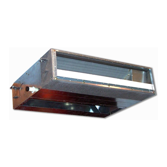
- Page 21 Heronhill - for all your Toshiba requirements Revised 2: Jun., 2008 1-1-6. Slim Duct Type <Single type> Indoor unit RAV-SM 404SDT-E 454SDT-E 564SDT-E Model Outdoor unit RAV-SP 404AT(Z)(ZG)-E 454AT(Z)(ZG)-E 562AT(Z)(ZG)-E Cooling capacity (kW) Heating capacity (kW) Power supply 1 phase 230V (220 – 240V) 50Hz Running current 5.20 –...
- Page 22 Heronhill - for all your Toshiba requirements Revised 2: Jun., 2008 <Single type> Indoor unit RAV-SM 564SDT-E Model Outdoor unit RAV-SM 563AT-E Cooling capacity (kW) Heating capacity (kW) Power supply 1 phase 230V (220 – 240V) 50Hz Running current 7.94 – 7.28...
- Page 23 Heronhill - for all your Toshiba requirements Revised 2: Jun., 2008 <Twin type> Indoor unit 1 RAV-SM 564SDT-E 564SDT-E Model Indoor unit 2 RAV-SM 564SDT-E 564SDT-E Outdoor unit RAV-SP 1104AT(Z)(ZG)-E 1102AT(Z)(ZG)-E Cooling capacity (kW) 10.0 10.0 Heating capacity (kW) 11.2 11.2...
- Page 24 Heronhill - for all your Toshiba requirements <Twin type> Indoor unit 1 RAV-SM 564SDT-E Model Indoor unit 2 RAV-SM 564SDT-E Outdoor unit RAV-SM 1103AT-E Cooling capacity (kW) 10.0 Heating capacity (kW) 11.2 Indoor unit Power supply 1 phase 230V (220 – 240V) 50Hz Running current 16.47 –...
-
Page 25: Outdoor Unit
Heronhill - for all your Toshiba requirements Revised 2: Jun., 2008 1-2. Outdoor Unit <Super Digital Inverter> Model name Outdoor unit RAV-SP 562AT(Z)(ZG)-E 802AT(Z)(ZG)-E 1104AT(Z)(ZG)-E 1404AT(Z)(ZG)-E 1 phase 230V (220 – 240V) 50Hz Power supply (Power exclusive to outdoor is required.) - Page 26 Heronhill - for all your Toshiba requirements Model name Outdoor unit RAV-SP 404AT(Z)(ZG)-E 454AT(Z)(ZG)-E 1 phase 230V (220 – 240V) 50Hz Power supply (Power exclusive to outdoor is required.) Type Hermetic compressor Compressor Motor (kW) Pole Refrigerant charged (kg) Refrigerant control...
-
Page 27: Operation Characteristic Curve
Heronhill - for all your Toshiba requirements 1-3. Operation Characteristic Curve • Operation characteristic curve <Super Digital Inverter> RAV-SP1104AT-E, RAV-SP1104ATZ-E, RAV-SP1104ATZG-E RAV-SP1404AT-E, RAV-SP1404ATZ-E, RAV-SP1404ATZG-E <Cooling> <Heating> SP110 SP110 SP140 SP140 SP140 SP140 SP110 SP110 • Conditions • Conditions Indoor : DB27˚C/WB19˚C Indoor : DB20˚C... - Page 28 Heronhill - for all your Toshiba requirements • Capacity variation ratio according to temperature RAV-SP404AT-E, RAV-SP404ATZ-E, RAV-SP404ATZG-E RAV-SP454AT-E, RAV-SP454ATZ-E, RAV-SP454ATZG-E RAV-SP1104AT-E, RAV-SP1104ATZ-E, RAV-SP1104ATZG-E RAV-SP1404AT-E, RAV-SP1404ATZ-E, RAV-SP1404ATZG-E <Cooling> <Heating> • Conditions • Conditions Indoor : DB27˚C/WB19˚C Indoor : DB20˚C Indoor air flow : High Indoor air flow : High Pipe length : 7.5m...
-
Page 29: Construction Views (External Views)
Heronhill - for all your Toshiba requirements 2. CONSTRUCTION VIEWS (EXTERNAL VIEWS) 2-1. Indoor Unit RAV-SM564UT-E 1000 or more 860 to 910 Ceiling open dimension An obstacle 1000 or more The space that is necessary for equipping and service Take-in port of wiring... - Page 30 Heronhill - for all your Toshiba requirements RAV-SM804UT-E 1000 or more 860 to 910 Ceiling open dimension An obstacle 1000 or more The space that is necessary for equipping and service Take-in port of wiring Bottom face of ceiling Indoor unit...
- Page 31 Heronhill - for all your Toshiba requirements Revised 2: Jun., 2008 RAV-SM1104UT-E, RAV-SM1404UT-E, RAV-SM1604UT-E 1000 or more 860 to 910 Ceiling open dimension An obstacle 1000 or more The space that is necessary for equipping and service Take-in port of wiring...
- Page 32 Heronhill - for all your Toshiba requirements RAV-SM404SDT-E, RAV-SM454SDT-E, RAV-SM564SDT-E 803 (inside) Refrigerant piping Air filter Fresh air inlet Drain-up port (knock-out hole) Hung-up plate – 32 – Tel: 01823 665660 www.heronhill.co.uk Fax: 01823 665807...
-
Page 33: Outdoor Unit
Heronhill - for all your Toshiba requirements Drain hole (Ø25) Air inlet B legs port Name Note Mounting bolt hole (Ø12 × 17 long hole) Air inlet port Refrigerant piping hole —— Indoor/Outdoor unit connecting wire inlet hole Power supply inlet hole Ø38 Kockout hole... - Page 34 Heronhill - for all your Toshiba requirements RAVSP404AT(Z)(ZG)-E, RAV-SP454AT(Z)(ZG)-E Drain hole Drain hole (Ø25) (2-Ø20 × 88 long hole) 2-Ø11-14 U-shape hole A legs (For Ø8-Ø10 anchor bolts) Connecting pipe port (Gas flare side: Ø12.7) Connecting pipe port (Liquid flare side: Ø6.4) 8-Ø6 hole...
- Page 35 Heronhill - for all your Toshiba requirements RAV-TWP30E2, RAV-TWP50E2 (Simultaneous Twin) Inner diameter Ø C Inner Inner diameter Ø D diameter Ø D Model (RBC-) Liquid side Ø9.5 Ø6.4 TWP30E2 Gas side Ø15.9 Ø12.7 Liquid side Ø9.5 Ø9.5 TWP50E2 Gas side Ø15.9 Ø15.9...
-
Page 36: Systematic Refrigerating Cycle Diagram
Heronhill - for all your Toshiba requirements Revised 2: Jun., 2008 3. SYSTEMATIC REFRIGERATING CYCLE DIAGRAM 3-1. Indoor Unit • Single type (Combination of 1 indoor unit and 1 outdoor unit) (Indoor unit) Distributor (Strainer incorporated) TCJ sensor Strainer Air heat... -
Page 37: Outdoor Unit
Heronhill - for all your Toshiba requirements 3-2. Outdoor Unit RAV-SP1104AT-E, SP1104ATZ-E, SP1104ATZG-E, RAV-SP1404AT-E, SP1404ATZ-E, SP1404ATZG-E TO sensor TS sensor TL sensor Strainer TE sensor Check joint Capillary Cooling: High pressure Ø4 ×Ø3 (6 pcs.) Heating: Low pressure Heat exchanger... - Page 38 Heronhill - for all your Toshiba requirements Revised 2: Jun., 2008 RAV-SP404AT-E, RAV-SP404ATZ-E, RAV-SP404ATZG-E RAV-SP454AT-E, RAV-SP454ATZ-E, RAV-SP454ATZG-E Packed valve Packed valve Outer dia. ØA Outer dia. ØB TS sensor (Pulse Motor Valve) (CAM-B30YGTF-2) TO sensor 2-step muffler Ø19.05 × 200L...
-
Page 39: Fan Characteristics
Heronhill - for all your Toshiba requirements 4. FAN CHARACTERISTICS 4-1. Slim Duct (Filter Attached) RAV-SM404SDT-E, RAV-SM454SDT-E Standard air volume : 690m³/h High (50Pa) Upper limit of external static pressure(50Pa) High Lower limit of (35Pa) external static Upper limit of... -
Page 40: Wiring Diagram
Heronhill - for all your Toshiba requirements Revised 2: Jun., 2008 5. WIRING DIAGRAM 5-1. Indoor Unit 5-1-1. 4-Way Air Discharge Cassette Type RAV-SM564UT-E, RAV-SM804UT-E, RAV-SM1104UT-E, RAV-SM1404UT-E, RAV-SM1604UT-E 1 2 3 4 5 1 2 3 4 5 1 2 3 4 5... - Page 41 Heronhill - for all your Toshiba requirements 5-1-2. Slim Duct Type RAV-SM404SDT-E, RAV-SM454SDT-E, RAV-SM564SDT-E CN333 (WHI) 1 2 3 6 7 8 9 10 11 12 13 14 15 16 17 18 19 20 1 2 3 CN510 CN504 CN34...
-
Page 42: Outdoor Unit
Heronhill - for all your Toshiba requirements 5-2. Outdoor Unit RAV-SP1104AT-E, SP1104ATZ-E, 1104ATZG-E RAV-SP1404AT-E, SP1404ATZ-E, 1404ATZG-E Reactor Reactor (RED) (WHI) (BLK) (GRY) (GRY) (WHI) (WHI) P04 P05 P06 P07 CN200 CN201 CN202 CN400 FM01 (WHI) CN300 FM02 (WHI) SW804 SW801 SW800... - Page 43 Heronhill - for all your Toshiba requirements CN500 Compressor CN300 Q200~205 Q300~305 P.C. Board IGBT MOS-FET (MCC-5009) R221 R321 Fan motor R220 R320 CN700 R219 R319 Pulse motor valve CAUTION : HIGH VOLTAGE Fuse Varistor T3.15A The high voltage circuit is AC250V incorporated.
-
Page 44: Specifications Of Electrical Parts
Heronhill - for all your Toshiba requirements Revised 2: Jun., 2008 6. SPECIFICATIONS OF ELECTRICAL PARTS 6-1. Indoor Unit RAV-SM564UT-E, RAV-SM804UT-E Parts name Type Specifications Fan motor (for indoor) SWF-230-60-2R Output (Rated) 60 W Thermo. sensor (TA-sensor) 328 mm 10 kΩ at 25°C Heat exchanger sensor (TCJ-sensor) Ø6 mm, 1000 mm... -
Page 45: Outdoor Unit (Parts Ratings)
Heronhill - for all your Toshiba requirements Revised 2: Jun., 2008 6-2. Outdoor Unit (Parts Ratings) RAV-SP1104AT-E, RAV-SP1104ATZ-E, RAV-SP1104ATZG-E RAV-SP1404AT-E, RAV-SP1404ATZ-E, RAV-SP1404ATZG-E Parts name Type Specifications Compressor DA422A3F-25M — Outdoor fan motor ICF-280-A100-1 Output 100W Reactor CH-62 5.7mH, 18.5A 4-way valve coil... -
Page 46: Refrigerant R410A
Heronhill - for all your Toshiba requirements 7. REFRIGERANT R410A This air conditioner adopts the new refrigerant HFC 6. When an air conditioning system charged with a (R410A) which does not damage the ozone layer. large volume of refrigerant is installed in a small... - Page 47 Heronhill - for all your Toshiba requirements Table 7-2-1 Thicknesses of annealed copper pipes Thickness (mm) Nominal diameter Outer diameter (mm) R410A 0.80 0.80 0.80 0.80 12.7 0.80 0.80 15.9 1.00 1.00 1. Joints For copper pipes, flare joints or socket joints are used. Prior to use, be sure to remove all contaminants.
- Page 48 Heronhill - for all your Toshiba requirements c) Insertion of Flare Nut d) Flare Processing Make certain that a clamp bar and copper pipe have been cleaned. By means of the clamp bar, perform the flare processing correctly. Use either a flare tool for R410A or conventional flare tool.
- Page 49 Heronhill - for all your Toshiba requirements Fig. 7-2-2 Relations between flare nut and flare seal surface 2. Flare Connecting Procedures and Precautions a) Make sure that the flare and union portions do not have any scar or dust, etc.
-
Page 50: Tools
Heronhill - for all your Toshiba requirements 7-3. Tools 7-3-1. Required Tools Refer to the “4. Tools” (Page 8) 7-4. Recharging of Refrigerant When it is necessary to recharge refrigerant, charge the specified amount of new refrigerant according to the following steps. -
Page 51: Brazing Of Pipes
Heronhill - for all your Toshiba requirements 1) Be sure to make setting so that liquid can be charged. 2) When using a cylinder equipped with a siphon, liquid can be charged without turning it upside down. It is necessary for charging refrigerant under condition of liquid because R410A is mixed type of refrigerant. - Page 52 Heronhill - for all your Toshiba requirements 2. Characteristics required for flux 7-5-3. Brazing • Activated temperature of flux coincides with As brazing work requires sophisticated techniques, the brazing temperature. experiences based upon a theoretical knowledge, it must be performed by a person qualified.
-
Page 53: Instructions For Re-Use Piping Of R22 Or R407C
Operation System age of the pipe at the worst. • In the concurrent twin system, when TOSHIBA- ∗ Pipe diameter and thickness (mm) specified branching pipe is used, it can be reused. -
Page 54: Final Installation Checks
Heronhill - for all your Toshiba requirements Revised 2: Jun., 2008 7-6-5. Final Installation Checks Is there no scratch or dent on the existing pipes? Existing pipe: NO * Use a new pipes. Is it possible to operate the existing air conditioner? ∗... - Page 55 Heronhill - for all your Toshiba requirements Revised 2: Jun., 2008 7-6-6. Handling of Existing Pipe RAV-SP1104AT-E, RAV-SP1404AT-E • To use an existing Ø19.1 mm pipe, set bit 3 of When using the existing pipe, carefully check it for SW802 (switch for existing pipe) on the P.C. board the following: of the outdoor unit to ON.
- Page 56 Heronhill - for all your Toshiba requirements Revised 2: Jun., 2008 7-6-7. Recovery Method of Refrigerant RAV-SP1104AT-E, RAV-SP1404AT-E RAV-SM1603AT-E • Use the refrigerant recovery switch SW801 on the • Use the refrigerant recovery switch SW802 on the P .C. board of the outdoor unit to recover refriger- P .C.
- Page 57 Heronhill - for all your Toshiba requirements 7-6-8. Recovery method of refrigerant for RAV-SP404AT-E, RAV-SP404ATZ-E, RAV-SP404ATZG-E RAV-SP454AT-E, RAV-SP454ATZ-E, RAV-SP454ATZG-E • When recovering refrigerant in case of reinstalla- tion of the indoor or outdoor unit, etc., use the refrigerant recovery switch on the terminal block of the outdoor unit.
-
Page 58: Indoor Control Circuit
Heronhill - for all your Toshiba requirements 8. INDOOR CONTROL CIRCUIT 8-1. Indoor Controller Block Diagram 8-1-1. Connection of Main (Sub) Remote Controller Main (sub) master remote controller (Max. 2 units) Weekly timer Display LCD Function setup Display LCD LCD driver... - Page 59 Heronhill - for all your Toshiba requirements 8-1-2. Connection of Wireless Remote Controller Kit Indoor unit #1 (Master) Wireless remote controller kit Receiver P .C. board (MCC-1504) Display LED Receive circuit Function setup SW Grille up/down SW Buzzer DC5V Power...
- Page 60 Heronhill - for all your Toshiba requirements 8-1-3. Connection of Both Main (Sub) Remote Controller and Wireless Remote Controller Kit Indoor unit #1 (Master) Main (sub) master remote controller Wireless remote controller kit (Max. 2 units) Weekly timer Receiver P.C. board...
-
Page 61: Control Specifications
Heronhill - for all your Toshiba requirements 8-2. Control Specifications Item Outline of specifications Remarks When power 1) Distinction of outdoor unit supply is reset When the power supply is reset, the outdoors are distin- guished and the control is selected according to the distinguished result. - Page 62 Heronhill - for all your Toshiba requirements Item Outline of specifications Remarks Room temp. 2) Using the Item code 06, the setup temperature in heating Shift of suction control operation can be corrected. temperature in heating (Continued) operation Setup data Setup temp.
- Page 63 Heronhill - for all your Toshiba requirements Item Outline of specifications Remarks Air speed selection 1) Operation with (HH), (H), (L) or [AUTO] mode is carried HH > H+ > H > L+ > out by the command from the remote controller.
- Page 64 Heronhill - for all your Toshiba requirements Revised 2: Jun., 2008 Item Outline of specifications Remarks Air speed Standard Type 1 Type 3 Type 6 selection Item code Selection of high [5d] (Continued): ceiling type In case of 4-way SW501 (1)/(2)
- Page 65 Heronhill - for all your Toshiba requirements Item Outline of specifications Remarks Air speed Slim Duct Type selection Selection of high static Standard Type 1 Type 3 Type 6 Item code (Continued): pressure type [5d] In case of Item code:...
- Page 66 Heronhill - for all your Toshiba requirements Item Outline of specifications Remarks Cool air discharge 1) In heating operation, the indoor fan is controlled In D and E zones, the preventive control based on the detected temperature of Tc sensor or priority is given to air Tcj sensor.
- Page 67 Heronhill - for all your Toshiba requirements Item Outline of specifications Remarks High-temp. 1) The heating operation is performed as follows based on the release control detected temperature of Tc sensor or Tcj sensor. • When [M] zone is detected, the commanded frequency is However this control is decreased from the real operation frequency.
- Page 68 Heronhill - for all your Toshiba requirements Item Outline of specifications Remarks Louver control: 1) Louver position setup The louver position In case of 4-way at horizontal • When the louver position is changed, the position moves Discharge discharge position...
- Page 69 Heronhill - for all your Toshiba requirements Item Outline of specifications Remarks Louver control <<Selection of Swing mode>> (Continued): • For the Swing mode, the following three types of modes are On the remote control- In case of 4-way SWING/FIX...
- Page 70 Heronhill - for all your Toshiba requirements Revised 2: Jun., 2008 Item Outline of specifications Remarks Louver control • If there is the locked louver in the unit, [ ] goes on the For the setting remote controller screen. operation, refer to...
- Page 71 Heronhill - for all your Toshiba requirements Item Outline of specifications Remarks Central control mode 1) Setting at the centerl controller side enables to select the selection contents which can be operated on the remote controller at indoor unit side.
- Page 72 Heronhill - for all your Toshiba requirements Item Outline of specifications Remarks DC motor 1) When the fan operation has started, positioning of the stator and the rotor are performed. (Moves slightly with tap sound) 2) The motor operates according to the command from the indoor controller.
- Page 73 Heronhill - for all your Toshiba requirements Item Outline of specifications Remarks 8°C heating/ 1) This functional is intended for the cold latitudes and performs Frost protective objective heating operation (8°C heating operation). operation 2) This function is valid only for combination with the outdoor In a group connection, units (Super Digital Inverter (SDI) 4-series outdoor units).
-
Page 74: Optional Connector Specifications Of Indoor P.c. Board
Heronhill - for all your Toshiba requirements Function Connector No. Pin No. Specifications Remarks Humidifier output is ON when heating operation is performed, when thermostat is on, when the fan is on. DC12V ∗ The setting of Humidifier provided + Drain pump ON is performed by short-circuit of CN70 or from the Humidifier output (∗) -
Page 75: Indoor Print Circuit Board
Heronhill - for all your Toshiba requirements Serial send LED Sub bus communication LED Micro computer operation LED D15 (Green) D504 (Green) D501 (Red) Optional power supply Serial receive LED DC fan return HA (T10) High ceiling select switch CN309 (Yellow), AC230V... -
Page 76: Circuit Configuration And Control Specifications
Heronhill - for all your Toshiba requirements 9. CIRCUIT CONFIGURATION AND CONTROL SPECIFICATIONS 9-1. Outdoor Controls 9-1-1. Print Circuit Board <Viewed from parts of P.C board> RAV-SP1104AT-E, RAV-SP1404AT-E RAV-SP1104ATZ-E, RAV-SP1404ATZ-E RAV-SP1104ATZG-E, RAV-SP1404ATZG-E <MCC-1571> Fan motor output Fan motor output Compressor output terminal... - Page 77 Heronhill - for all your Toshiba requirements F01, 02, 25A fuse P.C. board earth lead DB02: (Black) High power factor diode Q404: High power factor circuit IGBT C12, 13, 14 C12, 13, 14 electrolytic capacitor electrolytic capacitor F03: 3.15A fuse F03: 3.15A fuse...
-
Page 78: Outline Of Main Controls
Heronhill - for all your Toshiba requirements 9-2. Outline of Main Controls <In case of RAV-SP110 and SP140 models> 1. PMV (Pulse Motor Valve) control 1) PMV is controlled between 30 and 500 pulsed during operation. 2) In cooling operation, PMV is usually controlled with the temperature difference between TS sensor and TC sensor aiming 1 to 4K as the target value. - Page 79 Heronhill - for all your Toshiba requirements 3. Outdoor fan control Revolution frequency allocation of fan taps [rpm] SP110 SP140 Down — — 3-1) Cooling fan control The outdoor fan is controlled by TL sensor, TO sensor and the operation frequency.
- Page 80 Heronhill - for all your Toshiba requirements 4. Coil heating control 1) This control function heats the compressor by turning on the stopped compressor instead of a case heater. It purposes to prevent stagnation of the refrigerant inside of the compressor.
- Page 81 Heronhill - for all your Toshiba requirements 7. Current release value shift control Current release control value (11) 1) This control purposes to prevent troubles of the electronic parts such as the compressor Temperature range SP110, SP140 driving elements and the compressor during 44°C ≤...
- Page 82 Heronhill - for all your Toshiba requirements 10. Defrost control 1) In heating operation, defrost operation is performed when TE sensor satisfies any condition in A zone to D zone. 2) During defrosting operation, it finishes if TE sensor continued 12°C or higher for 3 seconds or continued 7°C ≤...
- Page 83 Heronhill - for all your Toshiba requirements <In case of RAV-SP40 and SP45 models> 1. Pulse Motor Valve (PMV) control 1) For PMV with 50 to 500 pulses during operation, respectively. 2) In cooling operation, PMV is controlled with the temperature difference between TS sensor and TC sensor.
- Page 84 Heronhill - for all your Toshiba requirements 4. Outdoor fan control Allocations of fan tap revolutions [rpm] SP40, SP45 1) Cooling fan control The outdoor fan is controlled by TE, TD, and TO sensors and also revolution frequency of the operation.
- Page 85 Heronhill - for all your Toshiba requirements 2) Heating fan control The outdoor fan is controlled by TE sensor, TO sensor and the operation frequency. (From Min. W1 to Max. are controlled according to the following table.) ‚ During 3 minutes after start-up, the fan is fixed with the maximum fan tap corresponding to zone in the following table.
- Page 86 Heronhill - for all your Toshiba requirements 6. Defrost control In heating operation, defrost operation is performed when TE sensor temperature satisfies any condition in A zone to C zone. ‚ The defrost operation is immediately finished if TE sensor temperature has become 12°C or more, or it also is finished when condition of 5°C <...
-
Page 87: Troubleshooting
Heronhill - for all your Toshiba requirements 10. TROUBLESHOOTING 10-1. Summary of Troubleshooting <Wired remote controller type> 1. Before troubleshooting 1) Required tools/instruments – • screwdrivers, spanners, radio cutting pliers, nippers, push pins for reset switch • Tester, thermometer, pressure gauge, etc. - Page 88 Heronhill - for all your Toshiba requirements <Wireless remote controller type> 1. Before troubleshooting 1) Required tools/instruments – • screwdrivers, spanners, radio cutting pliers, nippers, etc. • Tester, thermometer, pressure gauge, etc. 2) Confirmation points before check a) The following operations are normal.
-
Page 89: Troubleshooting
Heronhill - for all your Toshiba requirements <In case of SP110, SP140> 10-2. Troubleshooting 10-2-1. Outline of judgment The primary judgment to check whether a trouble occurred in the indoor unit or outdoor unit is carried out with the following method. - Page 90 Heronhill - for all your Toshiba requirements <In case of SP110, SP140> Lamp indication Check code Cause of trouble occurrence Operation Timer Ready Heat exchanger sensor (TCJ) error Heat exchanger sensor (TC) error Indoor unit sensor error ...
- Page 91 Heronhill - for all your Toshiba requirements <In case of SP110, SP140> 10-2-2. Others (Other than Check Code) Lamp indication Check code Cause of trouble occurrence Operation Timer Ready — During test run Simultaneous flash Operation Timer Ready Disagreement of cool/heat —...
- Page 92 Heronhill - for all your Toshiba requirements <In case of SP110, SP140> 10-2-3. Check Code List (Indoor) ¡ ¥ : Go on, : Flash, : Go off ALT (Alternate): Alternate flashing when there are two flashing LED SIM (Simultaneous): Simultaneous flashing when there are two flashing LED...
- Page 93 Heronhill - for all your Toshiba requirements <In case of SP110, SP140> Check Code List (Outdoor) ¡ ¥ : Go on, : Flash, : Go off ALT (Alternate): Alternate flashing when there are two flashing LED SIM (Simultaneous): Simultaneous flashing when there are two flashing LED...
- Page 94 Heronhill - for all your Toshiba requirements <In case of SP110, SP140> ¡ ¥ : Go on, : Flash, : Go off ALT (Alternate): Alternate flashing when there are two flashing LED SIM (Simultaneous): Simultaneous flashing when there are two flashing LED...
- Page 95 Heronhill - for all your Toshiba requirements <In case of SP110, SP140> Error mode detected by indoor unit Operation of diagnostic function Judgment and measures Check Status of Cause of operation Condition code air conditioner 1. Check cables of remote controller and communication adapters.
- Page 96 Heronhill - for all your Toshiba requirements <In case of SP110, SP140> Error mode detected by remote controller or central controller (TCC-LINK) Operation of diagnostic function Judgment and measures Status of Check code Cause of operation Condition air conditioner Power supply error of remote controller, Indoor EEPROM error 1.
- Page 97 Heronhill - for all your Toshiba requirements <In case of SP110, SP140> Error mode detected by outdoor unit The check code has been ramified from 4 series and after. The ramified check code is displayed only when both the indoor unit and the outdoor unit are 4 series and after.
- Page 98 Heronhill - for all your Toshiba requirements <In case of SP110, SP140> Operation of diagnostic function Check code Judgment and measures Indoor unit Status of Cause of operation Condition air conditioner before after 3 series 4 series 1. Check refrigerating cycle (Gas leak) Discharge temp.
- Page 99 Heronhill - for all your Toshiba requirements <In case of SP110, SP140> 10-2-4. Diagnostic Procedure for Each Check Code (Indoor Unit) Check code [E01 error] Correct inter-unit cable Is inter-unit cable of A and B normal? of remote controller Is there no disconnection or Correct connection of connector.
- Page 100 Heronhill - for all your Toshiba requirements <In case of SP110, SP140> [E04 error] Is group address setup of Does outdoor operate? Check Item code [14]. remote controller correct? Are wiring in indoor unit and Correct wiring and 1, 2, 3 inter-unit cables correct? inter-unit cables.
- Page 101 Heronhill - for all your Toshiba requirements <In case of SP110, SP140> Revised 2: Jun., 2008 [E18 error] Is inter-unit cable Correct inter-unit cable of A and B normal? of remote controller. Is there no disconnection or contact error of connector Correct connection of connector.
- Page 102 Heronhill - for all your Toshiba requirements [L20 error] Are wiring connections to communication lines Correct wiring connection. U3 and U4 normal? Is not the multiple same central Correct central control system address. control system addresses connected? Check central controller (including network adapter) and indoor P.C.
- Page 103 Heronhill - for all your Toshiba requirements [P10 error] Is connection of float switch connector Correct connection (Indoor control board CN34) of connector. normal? Does float switch work? Is circuit wiring normal? Check and correct wiring and wire circuit. Does drain pump work?
- Page 104 Heronhill - for all your Toshiba requirements <In case of SP110, SP140> Revised 2: Jun., 2008 [P12 error] Turn off the power. Is there no connection error or disconnection on connectors CN333 Correct connection and CN334 of indoor unit P.C. board of connector.
- Page 105 Heronhill - for all your Toshiba requirements <In case of SP110, SP140> Revised 2: Jun., 2008 [F02 error] Is connection of TC sensor connector Correct connection of connector. (CN101 on Indoor P.C. board) correct? Are characteristics of Replace TC sensor.
- Page 106 Heronhill - for all your Toshiba requirements <In case of SP110, SP140> [C06 error] (TCC-LINK central controller) Are U3 and U4 communication lines normal? Correct communication line. ∗1 Correct connection of connector. Is connection of connector normal? ∗1 TCC-LINK central: CN51 of TCC-LINK adapter P.C.
- Page 107 Heronhill - for all your Toshiba requirements <In case of SP110, SP140> [E03 error] (Master indoor unit) [E03 error] is detected when the indoor unit cannot receive a signal from the remote controller (also central controller). Check A and B remote controllers and communication lines of the central control system U3 and U4.
- Page 108 Heronhill - for all your Toshiba requirements <In case of SP110, SP140> 10-2-5. Diagnostic Procedure for Each Check Code (Outdoor Unit) 1) This section describes the diagnostic method for each check code displayed on the remote controller. 2) In some cases, a check code indicates multiple symptoms.
- Page 109 Heronhill - for all your Toshiba requirements <In case of SP110, SP140> Check Outdoor Check and troubleshooting code LED display (Item without special mention Indicates part of outdoor unit.) [F04] <Display 1> <Display 2> [Discharge temp. sensor (TD) error] ¡...
- Page 110 Heronhill - for all your Toshiba requirements <In case of SP110, SP140> Check Outdoor Check and troubleshooting code LED display (Item without special mention Indicates part of outdoor unit.) [F08] <Display 1> <Display 2> [Outside air temp. sensor (TO) error] ¡...
- Page 111 Heronhill - for all your Toshiba requirements <In case of SP110, SP140> Check Outdoor Check and troubleshooting code LED display (Item without special mention Indicates part of outdoor unit.) [H01] <Display 1> <Display 2> [Compressor break down] ¥ Is power supply voltage normal? ¡...
- Page 112 Heronhill - for all your Toshiba requirements <In case of SP110, SP140> Check Outdoor Check and troubleshooting code LED display (Item without special mention Indicates part of outdoor unit.) [H04] <Display 1> <Display 2> [Case thermostat operation] ¡ Are CN609 connection Correct connector.
- Page 113 Heronhill - for all your Toshiba requirements <In case of SP110, SP140> Check Outdoor Check and troubleshooting code LED display (Item without special mention Indicates part of outdoor unit.) ∗ There is a possibility that it is one of the following errors.
- Page 114 Heronhill - for all your Toshiba requirements <In case of SP110, SP140> Check Outdoor Check and troubleshooting code LED display (Item without special mention Indicates part of outdoor unit.) [P03] <Display 1> <Display 2> [Discharge temp. error] ¥ ¡ ¥...
- Page 115 Heronhill - for all your Toshiba requirements <In case of SP110, SP140> Check Outdoor Check and troubleshooting code LED display (Item without special mention Indicates part of outdoor unit.) [P07] <Display 1> <Display 2> [Heat sink overheat error] ¥ ¡...
- Page 116 Heronhill - for all your Toshiba requirements <In case of SP110, SP140> Check Outdoor Check and troubleshooting code LED display (Item without special mention Indicates part of outdoor unit.) [P19] <Display 1> <Display 2> [4-way valve inverse error] ¥ ¡...
- Page 117 Heronhill - for all your Toshiba requirements <In case of SP110, SP140> Check Outdoor Check and troubleshooting code LED display (Item without special mention Indicates part of outdoor unit.) [P20] <Display 1> <Display 2> [High pressure protective operation] ¡ ¡...
- Page 118 Heronhill - for all your Toshiba requirements <In case of SP110, SP140> Check Outdoor Check and troubleshooting code LED display (Item without special mention Indicates part of outdoor unit.) [P22] <Display 1> <Display 2> [Fan system error] ¡ ¥ ¡...
- Page 119 Heronhill - for all your Toshiba requirements <In case of SP110, SP140> Temperature sensor Temperature – Resistance value characteristic table TA, TC, TCJ, TE, TS, TO sensors TD, TL sensors Representative value Representative value Resistance value (kΩ Ω Ω Ω Ω ) Resistance value (kΩ...
- Page 120 Heronhill - for all your Toshiba requirements <In case of SP110, SP140> 10-2-6. Outline of judgment The primary judgment to check whether a trouble occurred in the indoor unit or outdoor unit is carried out with the following method. Method to judge the erroneous position by flashing indication on the display part of the indoor unit...
- Page 121 Heronhill - for all your Toshiba requirements <In case of SP110, SP140> Lamp indication Check code Cause of trouble occurrence Operation Timer Ready Heat exchanger sensor (TCJ) error Heat exchanger sensor (TC) error Indoor unit sensor error ...
- Page 122 Heronhill - for all your Toshiba requirements <In case of SP40, SP45> 10-2-8. Check Code List (Indoor) ¡ ¥ : Go on, : Flash, : Go off ALT (Alternate): Alternate flashing when there are two flashing LED SIM (Simultaneous): Simultaneous flashing when there are two flashing LED...
- Page 123 Heronhill - for all your Toshiba requirements <In case of SP40, SP45> Check Code List (Outdoor) ¡ ¥ : Go on, : Flash, : Go off ALT (Alternate): Alternate flashing when there are two flashing LED SIM (Simultaneous): Simultaneous flashing when there are two flashing LED...
- Page 124 Heronhill - for all your Toshiba requirements <In case of SP40, SP45> Error mode detected by indoor unit Operation of diagnostic function Judgment and measures Check Status of Cause of operation Condition code air conditioner 1. Check cables of remote controller and communication adapters.
- Page 125 Heronhill - for all your Toshiba requirements <In case of SP40, SP45> Error mode detected by remote controller or central controller (TCC-LINK) Operation of diagnostic function Judgment and measures Status of Check code Cause of operation Condition air conditioner Power supply error of remote controller, Indoor EEPROM error 1.
- Page 126 Heronhill - for all your Toshiba requirements <In case of SP40, SP45> Error mode detected by outdoor unit Operation of diagnostic function Judgment and measures Status of Check code Cause of operation Condition air conditioner 1. Check discharge temp. sensor (TD).
- Page 127 Heronhill - for all your Toshiba requirements <In case of SP40, SP45> 10-2-9. Diagnostic Procedure for Each Check Code (Indoor Unit) Check code [E01 error] Correct inter-unit cable Is inter-unit cable of A and B normal? of remote controller Is there no disconnection or Correct connection of connector.
- Page 128 Heronhill - for all your Toshiba requirements <In case of SP40, SP45> [E04 error] Is group address setup of Does outdoor operate? Check Item code [L07]. remote controller correct? Are wiring in indoor unit and Correct wiring and 1, 2, 3 inter-unit cables correct? inter-unit cables.
- Page 129 Heronhill - for all your Toshiba requirements <In case of SP40, SP45> [E18 error] Is inter-unit cable Correct inter-unit cable of A and B normal? of remote controller. Is there no disconnection or contact error of connector Correct connection of connector.
- Page 130 Heronhill - for all your Toshiba requirements <In case of SP40, SP45> [L20 error] Are wiring connections to communication lines Correct wiring connection. U3 and U4 normal? Is not the multiple same central Correct central control system address. control system addresses connected?
- Page 131 Heronhill - for all your Toshiba requirements <In case of SP40, SP45> Revised 2: Jun., 2008 [P10 error] Is connection of float switch connector Correct connection (Indoor control board CN34) of connector. normal? Does float switch work? Is circuit wiring normal? Check and correct wiring and wire circuit.
- Page 132 Heronhill - for all your Toshiba requirements <In case of SP40, SP45> [P12 error] Turn off the power. Is there no connection error or disconnection on connectors CN333 Correct connection and CN334 of indoor unit P.C. board of connector. (MCC-1570)?
- Page 133 Heronhill - for all your Toshiba requirements <In case of SP40, SP45> Revised 2: Jun., 2008 [F02 error] Is connection of TC sensor connector Correct connection of connector. (CN101 on Indoor P.C. board) correct? Are characteristics of Replace TC sensor.
- Page 134 Heronhill - for all your Toshiba requirements <In case of SP40, SP45> [C06 error] (TCC-LINK central controller) Are U3 and U4 communication lines normal? Correct communication line. ∗1 Correct connection of connector. Is connection of connector normal? ∗1 TCC-LINK central: CN51 of TCC-LINK adapter P.C.
- Page 135 Heronhill - for all your Toshiba requirements <In case of SP40, SP45> [E03 error] (Master indoor unit) [E03 error] is detected when the indoor unit cannot receive a signal from the remote controller (also central controller). Check A and B remote controllers and communication lines of the central control system U3 and U4.
- Page 136 Heronhill - for all your Toshiba requirements <In case of SP40, SP45> 10-2-10. Diagnostic Procedure for Each Check Code (Outdoor Unit) • This section describes the diagnostic method for each check code displayed on the remote controller. In some cases, a check code indicates multiple symptoms.
- Page 137 Heronhill - for all your Toshiba requirements <In case of SP40, SP45> Check and troubleshooting Check code (Item without special mention Indicates part of outdoor unit.) [F12] [Suction temp. sensor (TS) error] Is CN603 connection normal? Correct connector. Sensor error → Replace Is resistance value of TS sensor normal? Check outdoor P.C.
- Page 138 Heronhill - for all your Toshiba requirements <In case of SP40, SP45> Check and troubleshooting Check code (Item without special mention Indicates part of outdoor unit.) [P03] [Discharge temp. error] Is there no gas leak? Repair defective position. Is refrigerant charge amount adequate? Recharge refrigerant.
- Page 139 Heronhill - for all your Toshiba requirements <In case of SP40, SP45> Check and troubleshooting Check code (Item without special mention Indicates part of outdoor unit.) [P22] [Fan system error] Is there no problem on power supply voltage? Check wiring construction.
- Page 140 Heronhill - for all your Toshiba requirements <In case of SP40, SP45> Temperature sensor Temperature – Resistance value characteristic table T A, T C, T CJ, T E, T S, T O sensors T D, T L sensors Representative value Representative value Resistance value (kΩ...
-
Page 141: Replacement Of Service P.c. Board
Heronhill - for all your Toshiba requirements 11. REPLACEMENT OF SERVICE P.C. BOARD 11-1. Indoort Unit <Note: when replacing the P.C. board for indoor unit servicing> The nonvolatile memory (hereafter called EEPROM, IC503) on the indoor unit P .C. board before replacement... - Page 142 Heronhill - for all your Toshiba requirements [1] Setting data read out from EEPROM The setting data modified on the site, other than factory-set value, stored in the EEPROM shall be read out. TEST Step 1 Push button on the remote controller simultaneously for more than 4 seconds.
- Page 143 Heronhill - for all your Toshiba requirements Revised 2: Jun., 2008 Setting 4-way air discharge cassette Indoor Unit model only 1. Using the set temperature buttons, set “ ” to the CODE No. (DN). 2. Using the timer time buttons, set the data. (0001) •...
- Page 144 Heronhill - for all your Toshiba requirements Step 4 Write the on-site setting data to the EEPROM, such as address setting, etc. Perform the steps 1 and 2 above again. Step 5 Change the CODE No. (DN) to “ ” by pushing buttons for the temperature setting.
- Page 145 Heronhill - for all your Toshiba requirements Revised 2: Jun., 2008 Table 1. Setting data (CODE No. table (example)) Item Setting data Factory-set value Filter sign lighting time Depending on Type Filter pollution leve 0000: standard Central control address 0099: Not determined 0002: +2°C...
-
Page 146: Outdoor Unit
Heronhill - for all your Toshiba requirements <In case of SP110, SP140> 11-2. Outdoor Unit 1. Setting the jumper wires and DIP switches Part name Function Setting J800 to J803 Model switching Cut these jumper wires according to the following table. -
Page 147: Setup At Local Site And Others
Heronhill - for all your Toshiba requirements 12. SETUP AT LOCAL SITE AND OTHERS 12-1. Indoor Unit 12-1-1. Test Run Setup on Remote Controller <Wired remote controller> TEST 1. When pushing button on the remote controller for 4 seconds or more, “TEST” is displayed on LC display. - Page 148 Heronhill - for all your Toshiba requirements (Except 4-way Air Discharge Cassette Type and Under Ceiling Type) Remove a screw which fixes the name plate of the receiver part on the wireless remote controller. Remove the nameplate of the reciver section by inserting a minus screwdriver, etc. into the notch at the bottom of the plate, and set the Dip switch to [TEST RUN ON].
- Page 149 Heronhill - for all your Toshiba requirements <In case of wireless remote controller> Procedure Description Turn on power of the air conditioner. The operation is not accepted for 5 minutes when power has been turned on at first time after installation, and 1 minute when power has been turned on at the next time and after.
- Page 150 Heronhill - for all your Toshiba requirements 12-1-2. Forced Defrost Setup of Remote Controller (For wired remote controller only) (Preparation in advance) TEST Push buttons simultaneously for 4 seconds or more on the remote controller. (Push buttons while the air conditioner stops.) The first displayed unit No.
- Page 151 Heronhill - for all your Toshiba requirements 12-1-4. Function Selection Setup <Procedure> Perform setting while the air conditioner stops. TEST Push buttons simultaneously for 4 seconds or more. The first displayed unit No. is the master indoor unit address in the group control.
- Page 152 Heronhill - for all your Toshiba requirements Function selection item No. (DN) list Item Contents At shipment from factory 0000: None 0001: 150H Filter sign lighting time 0002: 2500H 0003: 5000H According to type 0004: 10000H 0005: Clogging sensor used...
- Page 153 Heronhill - for all your Toshiba requirements Item Contents At shipment from factory 0000: None 0000: 0.5 h to 0.012: 0 h Set when compressor-ON time is 10 to 60 minutes. Self-clean operation time 0002: 1 hour When ON-time is 60 minutes or more, the double of this operation time setting is set.
- Page 154 Heronhill - for all your Toshiba requirements 12-1-5. Wiring and Setting of Remote Controller Control 2-remote controller control <Wired remote controller> (Controlled by 2 remote controllers) How to set wired remote controller This control is to operate 1 or multiple indoor units as sub remote controller are operated by 2 remote controllers.
- Page 155 Heronhill - for all your Toshiba requirements 12-1-6. Monitor Function of Remote Controller Switch n Calling of sensor temperature display <Contents> Each data of the remote controller, indoor unit and outdoor unit can be understood by calling the service monitor mode from the remote controller.
-
Page 156: Calling Of Error History
Heronhill - for all your Toshiba requirements n Calling of error history <Contents> The error contents in the past can be called. <Procedure> TEST Push buttons simultaneously for 4 seconds or more to call the service check mode. TEMP. ON / OFF Service Check goes on, the item code 01 is displayed, and then the content of the latest alarm is displayed. - Page 157 Heronhill - for all your Toshiba requirements n Indoor unit power-ON sequence Power ON • The unit without power feed waits entirely → Waiting status is released by system start • Reboot when power is fed on the way <By feed unit>...
-
Page 158: Setup At Local Site / Others
Heronhill - for all your Toshiba requirements 12-2. Setup at Local Site / Others Model name: TCB-PCNT30TLE2 12-2-1. TCC-LINK Adapter (For TCC-LINK Central Control) 1. Function This model is an optional P .C. board to connect the indoor unit to TCC-LINK (Central controller). -
Page 159: Wiring Specifications
Heronhill - for all your Toshiba requirements 4. Wiring specifications • Use 2-core with no polar wire. • Match the length of wire to wire length of the central No. of wires Size control system. Up to 1000m: twisted wire 1.25mm If mixed in the system, the wire length is lengthened Up to 2000m: twisted wire 2.0mm... -
Page 160: How To Set Up Central Control Address Number
Heronhill - for all your Toshiba requirements 6. External view of P.C. board assembly Terminator (SW01) 7. Address setup In addition to set up the central control address, it is necessary to change the indoor unit number. (Line/Indoor/Group address). For details, refer to TCC-LINK Adapter Installation Manual. - Page 161 Heronhill - for all your Toshiba requirements 2. How to confirm the central control address (New function for AMT32 remote controller) <Procedure> It can be confirmed even during operation or stopping. UNIT LOUVER Push button for 4 seconds or more.
-
Page 162: How To Set Up Type Of Swing
Heronhill - for all your Toshiba requirements ∗ Dual swing 3. How to set up type of swing (Recommended for heating operation) <For only 4-way Discharge Cassette type> • The adjoined louvers repeat horizontal SWING/FIX discharge/Downward discharge alternately Push for 4 seconds or more during stop of to clear irregularity of the temperature in the operation. - Page 163 Heronhill - for all your Toshiba requirements 4. How to set louver lock (Louver fix) < For only 4-way Discharge Cassette type> Refrigerant pipe UNIT LOUVER Push (At the right side of the button) for Electric parts box 4 seconds or more during stop of the operation.
- Page 164 Heronhill - for all your Toshiba requirements 7. When installing separately sold filters REQUIREMENT • When you use this air conditioner for the first time, it takes approx. 5 minutes until the remote controller becomes available after power-on. This is normal.
- Page 165 Heronhill - for all your Toshiba requirements Be sure to make ceiling setting when installing When wireless remote controller is used separately sold filters. Change the high-ceiling and filter settings with the ∗ Separately sold filters cannot be installed in an DIP switch on the receiver section P .C.
-
Page 166: Outdoor Unit
Heronhill - for all your Toshiba requirements <In case of SP110, SP140> Revised 2: Mar., 2008 12-4. Outdoor Unit 12-4-1. Refrigerant Recovery Control The “ozone destruction coefficient” of HFC refrigerant is 0 and the W804: All OFF (As initial status) discharge regulation is set as anathermal effect gas. - Page 167 Heronhill - for all your Toshiba requirements <In case of SP110, SP140> 12-4-3. Service Support Function (LED Display, Switch Operation) 1. Outline A various setup and operation check can be performed by DIP switches at 3 positions (SW802, SW803, SW804) and the pushdown button switches (SW800, SW801) at 2 positions.
- Page 168 Heronhill - for all your Toshiba requirements <In case of SP110, SP140> 12-4-4. Others 1. Selection of LED display (SW800, SW803 operation) 1) Display selection list The displayed contents of LED D800 to D804 on the outdoor control P .C. board can be exchanged by operation of SW803.
- Page 169 Heronhill - for all your Toshiba requirements <In case of SP110, SP140> 2) Error display The error which is generating at present and the latest error (Latest error information including present) can be confirmed by lighting LED D800 toD804 on the outdoor control P .C. board.
- Page 170 Heronhill - for all your Toshiba requirements <In case of SP110, SP140> 3) Sensor, current, compressor operation frequency, PMV opening display The values detected by the controller, such as temperature sensor or current value are simply confirmed. (Legend) D800 (Yellow) D803 (Yellow) ¡...
- Page 171 Heronhill - for all your Toshiba requirements <In case of SP110, SP140> 4) Specific operation for maintenance check (SW801, SW804) The following specific operations for the maintenance check are performed by operation of SW801 or SW804. a) Select DIP switch SW804. (See table below) b) Push the pushdown button switch SW801 for approx.
- Page 172 Heronhill - for all your Toshiba requirements <In case of SP110, SP140> SW804 Operation when pushdown button switch SW801 is pushed 4-way valve relay operation (For RY700, CN70 check) Turn on 4-way valve power relay (RY700). SW804 When pushing SW801 again or when 2 minutes elapsed, the operation returns to the normal control.
-
Page 173: Address Setup
Heronhill - for all your Toshiba requirements Revised 2: Jun., 2008 13. ADDRESS SETUP 13-1. Address Setup Procedure When an outdoor unit and an indoor unit are connected, or when an outdoor unit is connected to each indoor unit respectively in the group operation even if multiple refrigerant lines are provided, the automatic address setup completes with power-ON of the outdoor unit. -
Page 174: Address Setup & Group Control
Heronhill - for all your Toshiba requirements Revised 2: Jun., 2008 13-2. Address Setup & Group Control <Terminology> Indoor unit No. : N - n = Outdoor unit line address N (Max. 30) - Indoor unit address n (Max. 64) - Page 175 Heronhill - for all your Toshiba requirements Revised 2: Jun., 2008 13-2-2. Automatic Address Example from Unset Address (No miswiring) 1. Standard (One outdoor unit) 1) Single (Master/Sub) Individual 2) Group operation (Twin, Triple operation) (Multiple outdoor units = Miltiple indoor units only with serial communication)
- Page 176 Heronhill - for all your Toshiba requirements Revised 2: Jun., 2008 13-2-3. Automatic Address Example from Unset Address (No miswiring) 1. Standard (One outdoor unit) 1) Single 2) Twin 3) Triple (1-1) (1-2) (1-1) (1-2) (1-3) Individual Master/Header Sub/Follower Sub/Header...
-
Page 177: Remote Controller Wiring
Heronhill - for all your Toshiba requirements Revised 2: Jun., 2008 13-3. Remote Controller Wiring <Single system> • Strip off approx. 9 mm the wire to be connected. Remote controller • For single system, use non polarity, 2 core wire is Remote controller used for wiring of the remote controller. -
Page 178: Address Setup (Manual Setting From Remote Controller)
Heronhill - for all your Toshiba requirements Revised 2: Jun., 2008 13-4. Address Setup (Manual setting from remote controller) In case that addresses of the indoor units will be (Example of 2-lines cabling) (Real line: Cabling, Broken line: Refrigerant pipe) -
Page 179: Confirmation Of Indoor Unit No. Position
Heronhill - for all your Toshiba requirements Revised 2: Jun., 2008 13-5. Confirmation of Indoor Unit No. Position 1. To know the indoor unit addresses though position of the indoor unit body is recognized • In case of individual operation (Wired remote controller : indoor unit = 1 : 1) (Follow to the procedure during operation) <Procedure>... - Page 180 Heronhill - for all your Toshiba requirements <Maintenance/Check list> Aiming in environmental preservation, it is strictly recommended to clean and maintain the indoor/outdoor units of the operating air conditioning system regularly to secure effective operation of the air conditioner. It is also recommended to maintain the units once a year regularly when operating the air conditioner for a long time.
-
Page 181: Detachments
Heronhill - for all your Toshiba requirements Revised 2: Jun., 2008 14. DETACHMENTS 14-1. Indoor Unit 14-1-1. 4-Way Air Discharge Cassette Type RAV-SM564UT-E, RAV-SM804UT-E, RAV-SM1104UT-E, RAV-SM1404UT-E, RAV-SM1604UT-E Part name Procedure Remarks Suction grille Suction grille Knobs of the XCAUTIONX suction grille hook Be sure to put on the gloves at disassembling work;... - Page 182 Heronhill - for all your Toshiba requirements Part name Procedure Remarks Electric parts cover (Continued) 1. Detachment Adjust corner cap Adjust corner cap 1) Pull knob of the adjust corner cap to the arrow direction, remove strap of the adjust corner cap from pin of the panel and then remove all the 4 corners of the cap.
- Page 183 Heronhill - for all your Toshiba requirements Part name Procedure Remarks 1. Detachment Ceiling panel Clamp 1) Carry out works of item 1 of and item 1 of 3 . Louv Louver motor wir Louver motor wiring er motor wiring...
- Page 184 Heronhill - for all your Toshiba requirements Part name Procedure Remarks 1. Detachment Control Clamp P .C. board 1) Carry out work of item 1 of 2) Remove connectors which are connected from the control P .C. board to the other parts and then remove wiring from the clamp.
- Page 185 Heronhill - for all your Toshiba requirements Part name Procedure Remarks 1. Detachment Drain cap Drain cap (outside) 1) Carry out work of item 1 of 2) Loosen screws (3 positions) fixing the drain cap (outside) and then turn the drain cap to the arrow mark direction to remove it.
- Page 186 Heronhill - for all your Toshiba requirements Part name Procedure Remarks 1. Detachment Fan motor Fixing screw A 1) Carry out work of item 1 of 2) Remove connectors which are connected from the control P .C. board to the other parts and then remove each wiring from the clamp.
- Page 187 Heronhill - for all your Toshiba requirements Part name Procedure Remarks 2. Attachment Fan motor M6 nut (Continued) 2) Fix the fan motor lead, TC sensor and TCJ sensor with the clamp of the bell mouth. 3) Mount the electric parts box with the fixing screws A and B.
- Page 188 Heronhill - for all your Toshiba requirements Part name Procedure Remarks 1. Detachment Drain pump Fixing screw A 1) Carry out works of item 1 of and item 1 of 6 . 2) Remove the drain pump connector Drain por...
- Page 189 Heronhill - for all your Toshiba requirements Part name Procedure Remarks 1. Detachment Float switch assembly 1) Carry out works of item 1 of and works from 1) to 5). Float s Float switch assemb Float switch assembly witch assembly 2) Remove the fixing screw and then remove the float switch assembly.
- Page 190 Heronhill - for all your Toshiba requirements Part name Procedure Remarks 1. Detachment Heat exchanger 1) Recover the refrigerant gas. 2) Carry out work of item 1 of 3) Remove refrigerant pipe at indoor unit side. 4) Remove the fixing screws and then remove the piping cover.
- Page 191 Heronhill - for all your Toshiba requirements 14-1-2. Slim Duct Type RAV-SM404SDT-E, RAV-SM454SDT-E, RAV-SM564SDT-E Part name Procedure Remarks XREQUIREMENTX Be sure to put on gloves at working; other- wise an injury may be caused by parts, etc. • Before replacement of the parts, be sure to stop operation of the air conditioner and turn off switch of the breaker.
- Page 192 Heronhill - for all your Toshiba requirements Part name Procedure Remarks 1. Detachment E-cover 1) Perform work 1. of 2) Take off screws fixing E-cover, and then remove hooks of the hooking part by lifting up. (Ø4 × 10, 2 pcs) 2.
- Page 193 Heronhill - for all your Toshiba requirements Part name Procedure Remarks 1. Detachment P .C. board assembly P.C. board assembly 1) Perform works 1. of 2 , 1. of 3 , and 1. of 4 . 2) Disconnect connectors which are connected from P .C.
- Page 194 Heronhill - for all your Toshiba requirements Part name Procedure Remarks 1. Detachment Fan motor 1) Perform works 1. of 2 , 1. of 3 , and 1. of 6 . 2) Remove lead wires which are connected to the following connectors of P .C.
- Page 195 Heronhill - for all your Toshiba requirements Part name Procedure Remarks 1. Detachment Drain pump, Float switch, 1) Perform works in procedures 1. of , 1. of Drain hose Drain hose , 1. of 8 . Hose band Drain pump 2) Disconnect lead wires which are connected to the following connectors of P .C.
-
Page 196: Outdoor Unit
Heronhill - for all your Toshiba requirements 14-2. Outdoor Unit RAV-SP1104AT-E, RAV-SP1104ATZ-E, RAV-SP1104ATZG-E RAV-SP1404AT-E, RAV-SP1404ATZ-E, RAV-SP1404ATZG-E Part name Procedure Remarks Common Front panel procedure XCAUTIONX Never forget to put on the gloves at working time; otherwise an injury will be caused by the parts, etc. - Page 197 Heronhill - for all your Toshiba requirements Part name Procedure Remarks 1. Detachment Discharge Motor base Discharge port cabinet port cabinet 1) Carry out work of 1 of Heat exchanger Partition board 2) Remove screws for the discharge port cabinet and the partition board.
- Page 198 Heronhill - for all your Toshiba requirements Part name Procedure Remarks 1. Control P.C. board Replacement of Control P.C. board Upper fan motor electric parts 1) Carry out work of 1 of Compressor Reactor lead case thermo. WARNINGX Never disassemble the inverter for...
- Page 199 Heronhill - for all your Toshiba requirements Part name Procedure Remarks 2. Reactor Replacement of Bundling band electric parts 1) Carry out work of 1 of (Compressor lead, Reactor lead) (Continued) 2) Remove the reactor lead connected to Control P.C. board Reactor lead the control P .C.
- Page 200 Heronhill - for all your Toshiba requirements Part name Procedure Remarks Fan motor 1) Carry out works of item 1 of 1 and work of 2 . 2) Remove the flange nut fixing the fan motor Propeller fan Propeller fan...
- Page 201 Heronhill - for all your Toshiba requirements Part name Procedure Remarks 1. Removal of defective compressor Compressor Piping panel (Front) Piping panel (Front) Compressor 1) Recover the refrigerant gas. lead 2) Carry out work of item 1 of and work of 3) Remove the piping panel (Front).
- Page 202 Heronhill - for all your Toshiba requirements Part name Procedure Remarks 2. Mounting of compressor Compressor Wrap the ferrite core with the compressor lead wire Compressor 1) Mount the compressor in the reverse for 4 times. lead procedure for removal.
- Page 203 Heronhill - for all your Toshiba requirements Part name Procedure Remarks 1. Detachment PMV coil Concave part PMV main unit 1) Carry out work of item 1 of 2) Turn the coil while pulling upward and then remove the coil from the PMV main unit.
- Page 204 Heronhill - for all your Toshiba requirements RAV-SP404AT-E, RAV-SP404ATZ-E, RAV-SP404ATZG-E RAV-SP454AT-E, RAV-SP454ATZ-E, RAV-SP454ATZG-E Part name Procedure Remarks Common procedure XCAUTIONX Valve cover Never forget to put on the gloves at working time, otherwise an injury will be caused by the parts, etc.
- Page 205 Heronhill - for all your Toshiba requirements Part name Procedure Remarks 1. Detachment Front cabinet Motor support 1) Perform work of item 1 of 2) Remove screws (ST1T Ø4 × 10L, 2 pcs.) of the front cabinet and the inverter cover.
- Page 206 Heronhill - for all your Toshiba requirements Part name Procedure Remarks 1. Detachment Inverter Screws assembly 1) Perform work of item 1 of 2) Take off screws of the upper part of the front cabinet. • If removing the inverter cover under this Front cabinet condition, P .C.
- Page 207 Heronhill - for all your Toshiba requirements Part name Procedure Remarks Control P .C. 1) Disconnect lead wires and connectors board assembly connected from the control P .C. board assembly to other parts. 1. Lead wires Take off • Connection with the power terminal earth screws.
- Page 208 Heronhill - for all your Toshiba requirements Part name Procedure Remarks Rear cabinet 1) Perform works of items 1 of 1 and 2 , 3 . 2) Take off fixed screws for the bottom plate. (ST1T Ø4 × 10L, 3 pcs.) 3) Take off fixed screws for the heat exchanger.
- Page 209 Heronhill - for all your Toshiba requirements Part name Procedure Remarks Compressor 1) Perform works of items 1 of 1 and 2 , Partition plate 2) Discharge refrigerant gas. 3) Remove the partition plate. (ST1T Ø4 × 10L, 2 pcs.) 4) Remove the noise-insulator.
- Page 210 Heronhill - for all your Toshiba requirements Part name Procedure Remarks 1. Detachment Pulse Motor Valve (PMV) coil Positioning extrusion 1) Perform works of items PMV body 2) Release the coil from the concavity by turning it, and remove coil from the PMV.
-
Page 211: Exploded Views And Parts List
Heronhill - for all your Toshiba requirements Revised 2: Jun., 2008 15. EXPLODED VIEWS AND PARTS LIST 15-1. Indoor Unit 15-1-1. 4-Way Air Discharge Cassette Type RAV-SM564UT-E, RAV-SM804UT-E, RAV-SM1104UT-E, RAV-SM1404UT-E, RAV-SM1604UT-E 223, 238 204, 205 214, 235 219, 220, 221,... - Page 212 Heronhill - for all your Toshiba requirements Revised 2: Jun., 2008 Model Name RAV-SM Location Part No. Description 564UT-E 804UT-E 1104UT-E 1404UT-E 1604UT-E 43120248 Fan Ass’y, Turbo, ABS 43120247 Fan Ass’y, Turbo, ABS 43166011 Remote Controller, SX-A4EE 4314J399 Refrigeration Cycle Ass’y 4314J400 Refrigeration Cycle Ass’y...
- Page 213 Heronhill - for all your Toshiba requirements Revised 2: Jun., 2008 RAV-SM564UT-E, RAV-SM804UT-E, RAV-SM1104UT-E, RAV-SM1404UT-E, RAV-SM1604UT-E Model Name RAV-SM Location Part No. Description 564UT-E / 804UT-E / 1104UT-E / 1404UT-E / 1604UT-E 43050425 Sensor Ass’y, TC (F6), Service 43050426 Sensor, TA, Service...
- Page 214 Heronhill - for all your Toshiba requirements Revised 2: Jun., 2008 RBC-U31PG (W, WS)-E, RBC-U31PGS (W, WS)-E 308, 309 306, 307, 323, 324 310, 311 Model Name RBC- Location Part No. Description U31PG (W)-E U31PG (WS)-E U31PGS (W)-E U31PGS (WS)-E...
- Page 215 Heronhill - for all your Toshiba requirements RBC-AX31U (W)-E, RBC-AX31U (WS)-E 356, 357 Model Name RBC- Location Part No. Description AX31U (W)-E AX31U (WS)-E 43459011 P.C. Board Ass’y, Remote Receiver 43462010 Cover, WRS, ABS 43461006 Sheet, PC 43108018 Cover, Panel, WRS...
- Page 216 Heronhill - for all your Toshiba requirements Revised 2: Jun., 2008 RAV-SM404SDT-E, RAV-SM454SDT-E, RAV-SM564SDT-EE 206, 209 213, 218, 224 225, 226, 231 TEST SETTING – 216 – Tel: 01823 665660 www.heronhill.co.uk Fax: 01823 665807...
- Page 217 Heronhill - for all your Toshiba requirements Revised 2: Jun., 2008 Model Name RAV-SM Location Part No. Description 404SDT-E 454SDT-E 564SDT-E 4312C040 Motor, Fan 43120227 Fan, Multi blade 43170244 Hose, Drain 4314J402 Refrigeration Cycle Ass’y 43122084 Case, Fan, Lower 43122085...
- Page 218 Heronhill - for all your Toshiba requirements Model Name RAV-SM Location Part No. Description 404SDT-E 454SDT-E 564SDT-E 43050425 Sensor Ass’y, Service TC (F6) 43050426 Sensor, Service 43160565 Terminal, Block, 3P , AC250V, 20A 43160568 Terminal, 2P , AC30V/DC42V, 1A P.C. Board Ass’y, 220–240V,...
-
Page 219: Outdoor Unit
Heronhill - for all your Toshiba requirements 15-2. Outdoor Unit RAV-SP1104AT-E, RAV-SP1104ATZ-E, RAV-SP1104ATZG-E RAV-SP1404AT-E, RAV-SP1404ATZ-E, RAV-SP1404ATZG-E 26, 32 31, 33 27, 37 4, 25 6, 9 7, 8, 36 – 219 – Tel: 01823 665660 www.heronhill.co.uk Fax: 01823 665807... - Page 220 Heronhill - for all your Toshiba requirements Model Name RAV-SP Location Part No. Description 1104AT-E 1404AT-E 1104ATZ-E 1404ATZ-E 1104ATZG-E 1404ATZG-E 43019904 Holder, Sensor, SUS 43032441 Nipple, Drain 43041794 Compressor, DA422A3F-25M 43047246 Bonnet, 3/8 IN 43047669 Nut, Flange 43197164 Nut, Flange, SUS304-WSB...
- Page 221 Heronhill - for all your Toshiba requirements RAV-SP1104AT-E, RAV-SP1104ATZ-E, RAV-SP1104ATZG-E RAV-SP1404AT-E, RAV-SP1404ATZ-E, RAV-SP1404ATZG-E 709, 710 Model Name RAV-SP Location Part No. Description 1104AT-E 1404AT-E 1104ATZ-E 1404ATZ-E 1104ATZG-E 1404ATZG-E 43050425 Sensor Ass’y, TC (F6), Service 43063325 Holder, Sensor, 6 - 6.35, 8 43150319 Sensor Ass’y, TD (F4), Service...
- Page 222 Heronhill - for all your Toshiba requirements RAV-SP454AT-E, RAV-SP454ATZ-E, RAV-SP454ATZG-E 16, 17 18, 19 12, 14 10, 26, 32 13, 15 – 222 – Tel: 01823 665660 www.heronhill.co.uk Fax: 01823 665807...
- Page 223 Heronhill - for all your Toshiba requirements Model Name RAV-SP Location Part No. Description 404AT-E 404ATZ-E 404ATZG-E 454AT-E 454ATZ-E 454ATZG-E 43105042 Cabinet, Front, RoHs 43105041 Cabinet, Upper 43005698 Cabinet, Side, Right, RoHs 43005672 Cabinet, Side, Left 4301V035 Guard, Fan 4301V053 Guard, Fin 43100346 Base Ass’y, RoHs...
- Page 224 Heronhill - for all your Toshiba requirements Model Name RAV-SP Location Part No. Description 404AT-E 404ARZ-E 404ATZG-E 454AT-E 454ATZ-E 454ATZG-E 43050422 Sensor, TE 43050423 Sensor, TS 43050427 Sensor, TO 43050430 Sensor, TD 43062228 Base, P .C.board 43160566 Terminal, Block 6P , 20A 4316V293 P .C.
- Page 225 Heronhill - for all your Toshiba requirements WARNINGS ON REFRIGERANT LEAKAGE Important Check of Concentration Limit The room in which the air conditioner is to be installed requires a design that in the event of NOTE 2 : refrigerant gas leaking out, its concentration will The standards for minimum room volume are as follows.
- Page 226 Heronhill - for all your Toshiba requirements TOSHIBA CARRIER CORPORATION 23-17, TAKANAWA 3 CHOME, MINATOKU, TOKYO, 108-8580, JAPAN Copyright © 1999 to 2007 TOSHIBA CARRIER CORPORATION, ALL Rights Reserved. Tel: 01823 665660 www.heronhill.co.uk Fax: 01823 665807...
Need help?
Do you have a question about the RAV-SM564UT-E and is the answer not in the manual?
Questions and answers