SEA GATE 1 DG R2BF Manual
Control unit for sliding gates, swing gates, barriers and garage doors
Hide thumbs
Also See for GATE 1 DG R2BF:
- Manual (44 pages) ,
- Owner's manual (24 pages) ,
- Quick start manual (20 pages)
Table of Contents
Advertisement
Quick Links
GATE 1 DG R2BF
CONTROL UNIT FOR SLIDING GATES, SWING GATES, BARRIERS AND GARAGE DOORS
SEA USA Inc.
10850 N.W. - 21st - unit 160 - Doral - MIAMI
Florida (FL) - 33172 - USA
Telephone
: ++1-305.594.1151
-
++1-305.594.7325
Toll free:
800.689.4716
www.sea-usa.com
sales@sea-usa.com
67410179
REV. 14 - 04/2021
Advertisement
Table of Contents

Related Manuals for SEA GATE 1 DG R2BF


Summary of Contents for SEA GATE 1 DG R2BF
- Page 1 GATE 1 DG R2BF CONTROL UNIT FOR SLIDING GATES, SWING GATES, BARRIERS AND GARAGE DOORS SEA USA Inc. 10850 N.W. - 21st - unit 160 - Doral - MIAMI Florida (FL) - 33172 - USA Telephone : ++1-305.594.1151 ++1-305.594.7325 Toll free: 800.689.4716...
- Page 2 IMPORTANT SAFETY INFORMATION GENERAL SAFETY PRECAUTIONS The following precautions are an integral and essential part of the product and must be supplied to the user; Read them carefully as they contain important indications for the safe installation, use and maintenance. 1.
-
Page 3: General Safety Information
GENERAL SAFETY INFORMATION An appliance shall be provided with an instruction manual. The instruction manual shall give instructions for the installation, operation, and user maintenance of the appliance. The installation instructions shall specify the need for a grounding-type receptacle for connection to the supply and shall stress the importance of proper grounding. - Page 4 The installer shall follow the provided instructions thoroughly. SEA products must only be used to automate doors, gates and wings. Any initiative taken without SEA USA Inc. explicit authorization will preserve the manufacturer from whatsoever responsibility.
- Page 5 NOTES: 1. The same type of device shall not be used for both entrapment protection means. Use of a single device to cover both the opening and closing directions is in accordance with the requirement; however, a single device is not required to cover both directions.
- Page 6 INDEX CHAPTER PAGE CHAPTER PAGE Connections Connections on CN6/CN7 Jumpers Pre-wired limit switch Connections on CN1 Non pre-wired limit switch Start Connections on CMS Partial opening Start Master / Slave Stop RECEIVERS on CNA/CNS Photocells 1 and 2 Connections on EXP 24V AUX 11.1 SEM 2 management unit...
-
Page 7: Technical Data
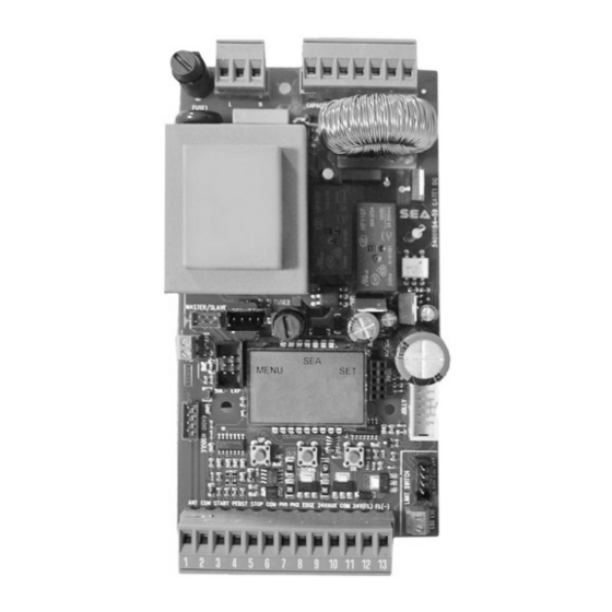
COMPONENTS INPUT OUTPUT 14 15 16 17 18 19 20 MOTOR CAPACITOR COUTESY LIGHT POWER SUPPLY 24V~ ENCODER PRE-WIRED LIMIT-SWITCH NOT PRE-WIRED LIMIT-SWITCH RX RECEIVER RF FIX RECEIVER PROGRAMMING EXTERNAL MODULE DISPLAY -------- -------- MASTER / SLAVE -------- -------- JOLLY 3 JOLLY SEACLOUD MOTOR CONTROL... - Page 8 ENGLISH Italiano International registered trademark n. 804888 1 - CONNECTIONS WARNING: CONNECT ALL DEVICES WITH SWITCHED-OFF CONTROL UNIT 14 15 16 17 18 19 20 LIGHT LIGHTN MCL MN MOP CAPACITOR ANT COM START PEDST STOP COM PH1 PH2 EDGE 24VAUX COM 24V(FL) (FL)- + - + - ENCODER 24Vac *...
- Page 9 ENGLISH Italiano International registered trademark n. 804888 3 - CONNECTIONS ON CN1 3.1 - START (N.O.) On clamps 2 and 3 The automation can be opened or closed through an impulse transmitted to this input (via key button, keyboard, etc.). To connect other Start devices (for ex.
-
Page 10: Safety Edge
ENGLISH Italiano International registered trademark n. 804888 EXAMPLE OF 3.7 - 24V FLASHING LIGHT - MAX 3W LAMP AND On clamps 12 and 13 SAFETY EDGE It warns of the gate movement by performing 1 blink per CONNECTION second on opening, 2 blinks per second on closing and remaining on steady during pause. -
Page 11: Safety Loop
ENGLISH Italiano International registered trademark n. 804888 3.11 - SAFETY LOOP EXAMPLE OF SAFETY LOOP CONNECTION Safety Exit Loop (Loop 1) Connection scheme of the C C2 C2 1 reader loop detector 7 = Photocell 1 contact (N.C.) Loop 1 6 = Common Safety Exit Shadow Loop (Loop 2) -
Page 12: External Receiver
ENGLISH Italiano International registered trademark n. 804888 3.13 - EXTERNAL RECEIVER EXAMPLE OF EXTERNAL RECEIVER An external receiver can be connected to CONNECTION the control unit according to the connection diagram. For more details on connections and functionalities of the external receiver, refer to the relative instruction manual 3.14 - LATCH OPENING OR LATCH CLOSING BUTTON... - Page 13 ENGLISH Italiano International registered trademark n. 804888 4.2 - THREE-PHASE MODULE CONNECTION On the 3-MOTOR menu, set «3 THREE-PHASE-BOLLARD» THREE-PHASE MODULE CONNECTORS 14 15 16 17 18 19 20 CN1 = On board power connector (220V) MCL MN MOP BIG 4000 CN2 = Motor connector (380V) THREE-PHASE SFT1 = Ground connection Faston...
- Page 14 ENGLISH Italiano International registered trademark n. 804888 CONNECTIONS ON 7.1 - ENCODER CONNECTION The ENCODER on board can be connected on CN5. In case of non pre-wired Encoder use an appropriate adapter green or black respecting the cable colors white or blue OLD TYPE ENCODER BROWN - WHITE - GREEN brown or red...
- Page 15 BARRIERS or BOLLARDS moved by two operators EACH MANAGED BY A CONTROL BOARD To work in Master/Slave it is necessary to use the (code SEA 23001220) consisting of MASTER/SLAVE KIT two circuits to be connected to the control units through the CMS connector; Then set a control unit as...
- Page 16 ENGLISH Italiano International registered trademark n. 804888 10 - RECEIVERS CONNECTIONS ON CNA AND CNS RF UNI RF FIX RF UNI PG RESPECT INSERTION SIDE 11 - CONNECTIONS ON EXP 11.1 - «SEM 2» MANAGEMENT UNIT CONNECTIONS SEM 2 The «SEM 2» management unit can be 14 15 16 17 18 19 20 connected through the EXP connector MANAGEMENT UNIT...
- Page 17 ENGLISH Italiano International registered trademark n. 804888 11.3 - «POSITION GATE» CONNECTION THROUGH «LSE» or «LE» UNITS Example: «LSE» Through the LSE management unit (or LE 14 15 16 17 18 19 20 MANAGEMENT UNIT management unit) it is possible to connect the «POSITION GATE», a potentiometer able to manage the correct position of the gate and the reversing on obstacle...
-
Page 18: Additional Functions
ENGLISH Italiano International registered trademark n. 804888 11.6 - ACCESS TO THE HIDDEN «DEBUG» MENU FOR POTENTIOMETER To view the instantaneous speed AT THE SAME TIME SEE CHAP. 13 values «VP1» (referred to the motor 1) VP 1 03.03 ACCESS THE HIDDEN «DEBUG» UP OK M E N U a s s h o w o n t h e s i d e The view of these values allows to... -
Page 19: Switching On The Control Unit
ENGLISH Italiano International registered trademark n. 804888 13 - DISPLAY AND PROGRAMMING WARNING! MAKE ALL DEVICES CONNECTIONS ON SWITCHED-OFF CONTROL UNIT BEFORE THE PARAMETERS CONFIGURATION THROUGH DISPLAY Starting from the software revision 03.02, the NEW BINGO DISPLAY OLD DISPLAY FROM SOFTWARE REV 03.02 PREVIOUS MANUALS electronic control unit is equipped with the new BINGO display with different DIAGNOSTIC... -
Page 20: Basic Menu Functions
ENGLISH Italiano International registered trademark n. 804888 14 - BASIC MENU FUNCTIONS PRESS TO CONFIRM MOVE THROUGH ENGLISH AND RETURN TO THE LANGUAGE MAIN MENU DOWN Skip this step if no need Tx programming TO CONFIRM AND EXIT Press the TX PRESS START MEMORIZED... - Page 21 ENGLISH Italiano International registered trademark n. 804888 15 - INPUT STATUS CHECK AND MANAGEMENT The input status check menu is displayed at the start of the control unit (for more details see chapter 13). Each input corresponds to a fixed position on the display, according to the diagram below and can be NORMALLY OPEN (N.O.) or NORMALLY CLOSED (N.C.) NORMALLY OPEN (N.O.)
- Page 22 ENGLISH Italiano International registered trademark n. 804888 15.2 - GATE 1 DG R2BF INPUT MANAGEMENT MENU Through this menu it is possible to activate or deactivate the inputs without repeating the self-learning LANGUAGE BACK TO THE START ENABLED STARTING MENU...
- Page 23 ENGLISH Italiano International registered trademark n. 804888 16 - WORKING TIMES SELF-LEARNING WARNING ! POTENTIALLY DANGEROUS PROCEDURE. TO BE PERFORMED EXCLUSIVELY BY SPECIALIZED INSTALLERS AND IN SAFETY CONDITIONS NOTE PRELIMINARY: It is not necessary to jumper Limit switches, Photocells, Stop or Safety Edges inputs if not used - Check the correct operation of all accessories (Photocells, Push buttons etc.) 16.1 - QUICK START The electronic unit on board the SLIDING...
- Page 24 ENGLISH Italiano International registered trademark n. 804888 16.4 - SELF-LEARNING WITH ENCODER OR POTENTIOMETER Working times self-learning through detection of the pulses by Encoder or Potentiometer PRELIMINARY NOTES: Check the activation and the correct reading of the Encoder (menu 32 and sub-menus 47 and 48 - see chapter 7) and of the Potentiometer (menu 32 and sub-menus 51 52 and 53 - see paragraph 11.4) WORKING TIMES SELF-LEARNING: AFTER THE ABOVE-MENTIONED CHECKS, FOLLOW THE PROCEDURE ILLUSTRATED IN THE PREVIOUS PARAGRAPH (16.2)
-
Page 25: Operating Logics
PRELIMINARY NOTES: 1) Once the password is enabled, the menu cannot be adjusted; 2) If You forgot the password, contact the SEA technical assistance; SEA will evaluate whether or not to provide the procedure for the control unit unlocking 3) Password CAN NOT be set through the JOLLY 3 programmer... - Page 26 Italiano International registered trademark n. 804888 19 - RECEIVERS AND REMOTE CONTROLS MAX NUMBER OF USERS SEA PLUG-IN RECEIVERS (see chapter 10) 16 USERS Without additional memory RF UNI 800 USERS With MEMO RF additional memory 100 USERS Fix Code...
- Page 27 ENGLISH Italiano International registered trademark n. 804888 19.2 - REMOTE CONTROLS PROGRAMMING TABLE PROGRAMMING PRESS THE BUTTON MENU TO BE STORED «START» COMMAND PRESS START STORED MUST ALWAYS BE LANGUAGE TRANSMITTERS BUTTON STORED ON THE TX PRESS THE BUTTON TO BE STORED PROGRAMMING OF PARTIAL PRESS...
- Page 28 GATE 1 DG R2BF MENU FUNCTIONS TABLE MENU DESCRIPTION DEFAULT NOTES Italiano Italian English English 1 LANGUAGE Français French English Español Spanish Dutch Dutch Start Start Partial opening Partial opening External module External module Stop Stop Pressed once, it stops the gate.
- Page 29 MENU DESCRIPTION DEFAULT NOTES To reverse the opening with the closing and vice-versa (both motors and limit-switches are reversed) 5 REVERSE MOTOR Automatic Automatic Open-stop-close-stop-open Step by step type 1 Open-stop-close-open Step by step type 2 Auto- 6 LOGIC matic 2 button Two buttons Safety...
-
Page 30: Special Menu
SPECIAL MENU PRESS AT THE SAME TIME FOR 5 SECONDS TO ENTER OR TO EXIT THE SPECIAL MENU SPECIAL MENU DESCRIPTION DEFAULT NOTES Motor 1 opening torque: by increasing the torque, more strength will be required depends 28 OPENING TORQ 1 to execute the inversion in case of obstacle. - Page 31 SPECIAL MENU DESCRIPTION DEFAULT NOTES adjust threshold potentiometer POTENTIOMETER intervention. This parameter self-determines during the THRESHOLD working times learning but can also be adjusted later, on OPENING 1 the condition that the set value is higher than the value depends 1000 shown in VP1 or VP2 (instantaneous speed values which POTENTIOMETER...
- Page 32 SPECIAL MENU DESCRIPTION DEFAULT NOTES Only opening If the gate is forced manually, the control unit starts the Only closing 79 ANTI INTRUSION motor and restores the state of the gate before forcing Opening and closing (function only available if limit switches are installed) Opening and closing The gate leaf makes an extra movement at the maximum 80 PUSHOVER...
- Page 33 SPECIAL MENU DESCRIPTION DEFAULT NOTES Disabled On Photo2 The function can be enabled on the Photocell 2 input FIRE SWITCH The function can be enabled on the partial opening Start On partial input input Always AUX output always powered In cycle AUX output powered only during cycle Opening AUX output powered only during opening...
- Page 34 SPECIAL MENU DESCRIPTION DEFAULT NOTES If the photocell is occupied during closing, the gate Closing reverses the movement; If the photocell is occupied during the pause, it prevents the gate reclosing If the photocell is occupied during opening or closing, it Opening and closing stops the gate movement;...
- Page 35 SPECIAL MENU DESCRIPTION DEFAULT NOTES If the photocell is occupied during closing, the gate Closing reverses the movement; If the photocell is occupied during the pause, it prevents the gate reclosing If the photocell is occupied during opening or closing, it Opening and closing stops the gate movement;...
- Page 36 SPECIAL MENU DESCRIPTION DEFAULT NOTES Opening and closing Safety edge enabled in opening and closing Opening SAFETY EDGE 1 Only opening Safety edge enabled only in opening DIRECTION Closing Only closing Safety edge enabled only in closing Opening and closing Safety edge enabled in opening and closing Opening SAFETY EDGE 2...
- Page 37 SPECIAL MENU DESCRIPTION DEFAULT NOTES Disabled The gate opens and stay open till a new Start input. Opening The latch function uses the "Partial Opening" N.O. input 118 LATCH (the "Partial Opening" function is so disabled) The gate closes and stay closed till a new Start input. Closing The latch function uses the "Partial Opening"...
- Page 38 ENGLISH Italiano International registered trademark n. 804888 ALARMS The control unit advises about faults by a message on the display. The table below shows which faults are advised and what to do in the event of a malfunction. However, it is possible to read the last 10 fault warnings by accessing the 106-DIAGNOSTIC menu Note 1: To exit the alarms display press OK If the warning signal does not disappear, carry out all the checks required for that error or disconnect the...
-
Page 39: Troubleshooting
ENGLISH Italiano International registered trademark n. 804888 TROUBLESHOOTING Advices Make sure all Safeties are turned ON Problem Found Possible Cause Solutions a) Check the connections or the jumpers on the connections of Operator doesn’t respond to a) Check the connected N.C. contacts the safety edge or of the stop and of the photocell if connected any START impulse b) Burnt fuse... - Page 40 ENGLISH Italiano International registered trademark n. 804888 Advices Make sure all Safeties are turned ON Problem Found Possible Cause Solutions a) Check menu for encoder parameters "Encoder Par" shall be from a low value +/- 10 (gate completely closed) to "Encoder a) ENCODER is not working properly if It's tot"...
- Page 41 PRICES: Prices are based on the Price List in force. Discounts and quotation from Sales Dep. and other selling branches must be approved by SEA. Prices are F.O.B SEA Warehouse in Miami and do not include shipments costs. SEA reserves the right to modify the price list at any time and provide notice to its sales network.
- Page 42 NOTES...
- Page 44 SEA USA Inc. 10850 N.W. 21st - unit 160 - DORAL - MIAMI Florida (FL) 33172 Phone: ++1-305.594.1151 Toll Free: 800.689.4716 www.sea-usa.com sales@sea-usa.com...
Need help?
Do you have a question about the GATE 1 DG R2BF and is the answer not in the manual?
Questions and answers