SEA GATE 1 DG R2BF Manual
Control unit for sliding gates, swing gates barriers and garage doors
Hide thumbs
Also See for GATE 1 DG R2BF:
- Manual (44 pages) ,
- Owner's manual (24 pages) ,
- Quick start manual (20 pages)
Table of Contents
Advertisement
Quick Links
Advertisement
Table of Contents

Related Manuals for SEA GATE 1 DG R2BF


Summary of Contents for SEA GATE 1 DG R2BF
- Page 1 CONTROL UNIT FOR SLIDING GATES SWING GATES ARRIERS AND GARAGE DOORS SEA USA Inc. 10850 N.W. - 21st - unit 160 - Doral - MIAMI Florida (FL) - 33172 - USA Telephone ++1-305.594.1151 ++1-305.594.7325 Toll free: 800.689.4716 www.sea-usa.com sales@sea-usa.com 67410179...
-
Page 2: General Safety Precautions
GENERAL SAFETY PRECAUTIONS The following precautions are an integral and essential part of the product and must e supplied to the user ead them carefully as they contain important indications for the safe installation use and maintenance. 1. These instruction must e kept and forwarded to all possi le future users of the system. 2. -
Page 3: General Safety Information
GENERAL SAFETY INFORMATION An appliance shall e provided with an instruction manual. The instruction manual shall give instructions for the installation operation and user maintenance of the appliance. The installation instructions shall specify the need for a grounding-type receptacle for connection to the supply and shall stress the importance of proper grounding. - Page 4 The installer shall provide warning notices on not assessa le further risks. SEA USA nc. in its relentless aim to improve the products is allowed to make whatsoever ad ustment without giving notice. This doesn t o lige SEA to up-grade the past production. SEA USA nc.
- Page 5 5. The End of T pe E. Type E audi le alarm devices can no longer e used for entrapment protection. This change was made ecause the Type E device is really a warning device not an entrapment-protection device. Also all gate operator classes are now re uired to have an audio alarm that sounds when two successive o structions are encountered via a contact-type system.
- Page 6 INDEX CHAPTER PAGE CHAPTER PAGE Components Dry contact Connections 24V contact umpers Connections on CN6 Connections on CN1 Motor connection Start Connections on CN7 Partial opening Start Battery connection Stop Connections on CN8 Photocells 1 and 2 10.1 Control unit power supply 24V AUX Connections on E P Timer...
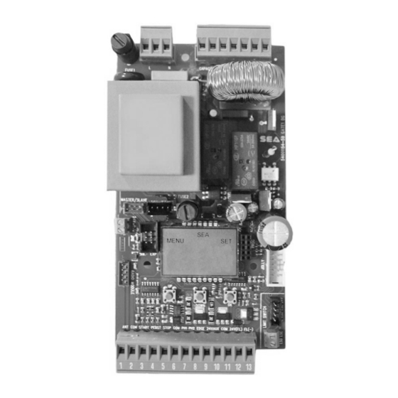
- Page 7 INPUT OUTPUT 14 15 16 17 18 19 20 MOTOR CAPACITOR COUTESY LIG T POWER SUPPLY ENCODER PRE-WIRED LIMIT-SWITC NOT PRE-WIRED LIMIT-SWITC R RECEIVER RF FI RECEIVER PROGRAMMING E TERNAL MODULE DISPLAY -------- -------- MASTER SLAVE -------- -------- OLLY 3 OLLY SEACLOUD MOTOR CONTROL...
- Page 8 WARNING: CONNECT ALL DEVICES WITH SWITCHED-OFF CONTROL UNIT 14 15 16 17 18 19 20 LIGHT LIGHTN MCL MN MOP CAPACITOR ANT COM START PEDST STOP COM PH1 PH2 EDGE 24VAUX COM 24V(FL) (FL)- + - + - ENCODER 24Vac Ma .
- Page 9 3.1 - START (N.O.) On clamps 2 and 3 The automation can e opened or closed through an impulse transmitted to this input via key utton key oard etc. . To connect other Start devices for ex. the magnetic loop refer to the respective instructions Note 1: For details on the logics that can e associated to the utton see chapter...
-
Page 10: Safety Edge
EXAMPLE OF 3.7 - 24V FLAS ING LIG T - MA 3W LAMP AND On clamps 12 and 13 SAFETY EDGE t warns of the gate movement y performing 1 link per CONNECTION second on opening 2 links per second on closing and remaining on steady during pause. -
Page 11: Safety Loop
3.11 - SAFETY LOOP EXAMPLE OF SAFETY LOOP CONNECTION Safet E it Loop (Loop 1) Connection scheme of the C C2 C2 1 reader loop detector Photocell 1 contact (N.C.) Loop 1 Common Safety Exit Shadow Loop (Loop 2) Loop1 Connection scheme of the Loop 2 2 readers loop detector... - Page 12 3.13 - E TERNAL RECEIVER EXAMPLE OF EXTERNAL RECEIVER An external receiver can e connected to CONNECTION the control unit according to the connection diagram. For more details on connections and functionalities of the external receiver refer to the relative instruction manual 3.14 - LATC OPENING OR LATC CLOSING UTTON On clamps 4 and 6...
-
Page 13: Control Unit Connection
4.2 - T REE-P ASE MODULE CONNECTION On the 3-MOTOR menu, set «3 THREE-PHASE-BOLLARD» T REE-P ASE MODULE CONNECTORS 14 15 16 17 18 19 20 n oard power connector 220V MCL MN MOP IG 4000 Motor connector 380V T REE-P ASE SFT1 round connection Faston 230V... -
Page 14: Encoder Connection
7.1 - ENCODER CONNECTION The ENCODER on oard can e connected on CN5. n case of non pre-wired Encoder use an appropriate adapter green or black respecting the ca le colors white or blue OLD TYPE ENCODER BROWN - WHITE - GREEN brown or red NEW TYPE ENCODER RED - BLUE - BLACK... -
Page 15: Important Notes
4) For a correct operation of the limit switches there must e a correspondence etween the direction of movement of the motors and the respective limit switches involved. 5) For SEA magnetic limit switches set the menu 104-SELECT LIMIT SWITC on «N.O.»... - Page 16 E EI E RF FI RF UNI RF UNI PG RESPECT INSERTION SIDE N EX 11.1 - SEM 2 MANAGEMENT UNIT CONNECTIONS SEM 2 SEM 2 management unit can 14 15 16 17 18 19 20 connected through the E P connector MANAGEMENT UNIT The SEM 2 unit manages 24V~ / (ac/dc)
- Page 17 11.3 - POSITION GATE CONNECTION T ROUG LSE or LE UNITS Example: «LSE» Through the LSE management unit or LE 14 15 16 17 18 19 20 MANAGEMENT UNIT management unit it is possi le to connect POSITION GATE a potentiometer a le to manage the correct position of the gate and the reversing on o stacle POSITION GATE can be enabled on menu...
- Page 18 11.6 - ACCESS TO T E IDDEN DE UG MENU FOR POTENTIOMETER AT THE SAME TIME To view the set values maximum SEE CHAP. 13 speed threshold and maximum VP 1 03.02 deceleration threshold ACCESS UP OK DDEN «DEBUG» MENU: DDI I N 12.1 - AMPEROMETRIC MANAGEMENT The control unit is e uipped with an o stacle detection system (working ONLY on ELECTRO-...
- Page 19 WARNING MA E ALL DEVICES CONNECTIONS ON SWITC ED-OFF CONTROL UNIT EFORE T E PARAMETERS CONFIGURATION T ROUG DISPLAY Starting from the software revision 03.02 the NEW INGO DISPLAY OLD DISPLAY FROM SOFTWARE REV 03.02 PREVIOUS MANUAL electronic control unit is e uipped with the new BINGO display with different DIAGNOSTIC MENU 01000100...
- Page 20 PRESS TO CONFIRM MOVE T ROUG ENGLIS AND RETURN TO T E LANGUAGE MAIN MENU DOWN Skip this step if no need Tx programming TO CONFIRM AND EXIT Press the TX PRESS START MEMORI ED button TRANSMITTERS UTTON Press next Tx button to be stored to be stored if this...
- Page 21 E EN The input status check menu is displayed at the start of the control unit for more details see chapter 13 . Each input corresponds to a fixed position on the display according to the diagram elow and can e NORMALLY OPEN (N.O.) or NORMALLY CLOSED (N.C.) NORMALLY OPEN N.O.
- Page 22 15.2 - GATE 1 DG R2 F INPUT MANAGEMENT MENU Through this menu it is possible to activate or deactivate the inputs without repeating the self-learning LANGUAGE BACK TO THE START ENABLED STARTING MENU START BACK TO THE START DISABLED STARTING MENU DOWN BACK TO THE...
- Page 23 WARNING POTENTIALLY DANGEROUS PROCEDURE. TO E PERFORMED E CLUSIVELY Y SPECIALI ED INSTALLERS AND IN SAFETY CONDITIONS NOTE PRELIMINARI: t is not necessary to umper Limit switches Photocells Stop or Safety Edges inputs if not used - Check the correct operation of all accessories Photocells Push uttons etc. 16.1 - QUIC START The electronic unit on oard the SLIDING...
- Page 24 16.4 - SELF-LEARNING WIT ENCODER OR POTENTIOMETER orking times self-learning through detection of the pulses y Encoder or Potentiometer PRELIMINARY NOTES: Check the activation and the correct reading of the Encoder menu 32 and su -menus 47 and 48 - see chapter 7 and of the Potentiometer menu 32 and su -menus 51 52 and 53 - see paragraph 11.4 WOR ING TIMES SELF-LEARNING: AFTER T E A OVE-MENTIONED C EC S FOLLOW T E PROCEDURE ILLUSTRATED IN T E PREVIOUS PARAGRAP (16.2)
- Page 25 PRELIMINARY NOTES: 1) nce the password is ena led the menu cannot be ad usted 2) f ou forgot the password contact the SEA technical assistance SEA will evaluate whether or not to provide the procedure for the control unit unlocking...
- Page 26 E EI E ND E MA NUM ER OF USERS SEA PLUG-IN RECEIVERS (see chapter 10) 16 USERS ithout additional memory RF UNI 800 USERS ith MEM F additional memory 100 USERS Fix Code RF UNI PG (Old Model - non-extractable memory)
- Page 27 19.2 - REMOTE CONTROLS PROGRAMMING TA LE PROGRAMMING PRESS THE BUTTON MENU TO BE STORED «START» COMMAND PRESS START STORED MUST ALWAYS BE LANGUAGE TRANSMITTERS BUTTON STORED ON THE TX PRESS THE BUTTON TO BE STORED PROGRAMMING OF PARTIAL PRESS THE PARTIAL OPENING STORED OPENING...
- Page 28 GATE 1 DG R2BF MENU FUNCTIONS TABLE MENU DESCRIPTION DEFAULT NOTES Italiano Italian English English 1 LANGUAGE Français French English Español Spanish Dutch Dutch Start Start Partial opening Partial opening External module External module Stop Stop Pressed once, it stops the gate. Pressed twice, it...
- Page 29 MENU DESCRIPTION DEFAULT NOTES In On reverses the opening with the closing and/or vice-versa (Note: both motors and limit-swiches are 5 REVERSE MOTOR reversed) Automatic Automatic Step by step type 1 Open-stop-close-stop-open Open-stop-close-open Step by step type 2 Auto- 6 LOGIC matic 2 button Two buttons...
-
Page 30: Special Menu
SPECIAL MENU U P DOWN PRESS AT THE SAME TIME FOR 5 SECONDS TO ENTER OR TO EXIT THE SPECIAL MENU SPECIAL MENU FUNCTIONS TABLE GATE 1 DG R2BF SP MENU DESCRIPTION DEFAULT NOTES Opening torque Motor 1: by increasing the... - Page 31 SP MENU DESCRIPTION DEFAULT NOTES Adjusts the threshold of the potentiometer POTENTIOMETER intervention. This parameter self-determines THRESHOLD during learning but can also be adjusted later. OPENING 1 The lower the value, the slower will be the depends 1000 response of the potentiometer. The parameter POTENTIOMETER model can be set as maximum threshold (VP1 value).
- Page 32 SP MENU DESCRIPTION DEFAULT NOTES Only opening If the gate is forced manually, the control unit Only closing 79 ANTI INTRUSION starts the motor to restore the state of the gate Opening and closing before forcing (only with limit switch) Opening and closing Allows the leaf to make an extra move at 80 PUSHOVER...
- Page 33 SP MENU DESCRIPTION DEFAULT NOTES Turn the selected input into an input to which 92 TIMER On photo2 connecting an external clock On partial entry Disabled FIRE SWITCH On Photo2 Function active on Photocell 2 On Partial entry Function active on Partial entry input Always AUX output always powered In cycle...
- Page 34 SP MENU DESCRIPTION DEFAULT NOTES If the photocell is occupied during closing, it reverses the movement; If the photocell is Closing occupied during the pause, it prevents the reclosing If occupied, the photocell blocks the movement Opening as long as it is busy; when released, the opening movement continues If the photocell is occupied before the Start input, the Start will be ignored.
- Page 35 SP MENU DESCRIPTION DEFAULT NOTES If the photocell is occupied during closing, it Closing reverses the movement; If it is occupied during the pause, it prevents the reclosing If occupied, the photocell blocks the movement Opening as long as it is busy; when released, the opening movement continues If the photocell is occupied before the Start input, the Start will be ignored.
- Page 36 SP MENU DESCRIPTION DEFAULT NOTES Opening and closing Active in opening and closing Opening SAFETY EDGE 1 Only opening Active only in opening DIRECTION Closing Only closing Active only in closing Opening and closing Active in opening and closing Opening SAFETY EDGE 2 Only opening Active only in opening...
- Page 37 SP MENU DESCRIPTION DEFAULT NOTES In the event of a power failure, if the door has been manually opened, it closes only after the 117 ALWAYS CLOSE 240 seconds set time has elapsed (from 0 to 240 s) , as soon as the power is restored Disabled Uses the "Edge 1"...
- Page 38 The control unit advises a out faults y a message on the display. The ta le elow shows which faults are advised and what to do in the event of a malfunction. owever it is possi le to read the last 10 fault warnings y accessing the 106-DIAGNOSTIC menu Note 1: To exit the alarms display press OK If the warning signal does not disappear, carry out all the checks required for that error or disconnect the...
- Page 39 Ad ices Make sure all Safeties are turned ON Problem Found Possible Cause Solutions a) Check the connections or the jumpers on the connections of Operator doesn’t respond to a) Check the connected N.C. contacts the safety edge or of the stop and of the photocell if connected any START impulse b) Burnt fuse b) Replace the burnt fuse on the control unit...
- Page 40 Ad ices Make sure all Safeties are turned ON Problem Found Possible Cause Solutions a) Check menu for encoder parameters "Encoder Par" shall be from a low value +/- 10 (gate completely closed) to "Encoder a) ENCODER is not working properly if It's tot"...
- Page 41 GENERAL WARNING: nstallation must e realized using parts and accessories approved y SEA. SEA is not responsi le for incorrect installations and/or non-compliance with safety standards according to the law in-force. SEA is in no way lia le for any damages and/or malfunctioning due to using parts and accessories non-compliant with the UL325 safety standards.
- Page 42 NOTES...
- Page 44 SEA USA Inc. 10850 N.W. 21st - unit 160 - DORAL - MIAMI Florida (FL) 33172 Phone: ++1-305.594.1151 Toll Free: 800.689.4716 www.sea-usa.com sales@sea-usa.com...
Need help?
Do you have a question about the GATE 1 DG R2BF and is the answer not in the manual?
Questions and answers