SEA GATE 1 DG R2BF Manual
Control unit for sliding gates, swing gates, barriers and garage doors
Hide thumbs
Also See for GATE 1 DG R2BF:
- Manual (44 pages) ,
- Owner's manual (24 pages) ,
- Quick start manual (20 pages)
Table of Contents
Advertisement
Quick Links
®
English
Sistemi Elettronici
di Apertura Porte e Cancelli
International registered trademark n. 804888
GATE 1 DG R2BF
CONTROL UNIT FOR SLIDING GATES, SWING GATES, BARRIERS AND GARAGE DOORS
(Cod. 23001158)
SEA S.p.A.
Zona industriale 64020 S.ATTO Teramo - (ITALY)
Tel. +39 0861 588341 r.a. Fax +39 0861 588344
www.seateam.com
seacom@seateam.com
Rev.10 - 01/2018
67410182
Advertisement
Table of Contents

Related Manuals for SEA GATE 1 DG R2BF


Summary of Contents for SEA GATE 1 DG R2BF
- Page 1 ® English Sistemi Elettronici di Apertura Porte e Cancelli International registered trademark n. 804888 GATE 1 DG R2BF CONTROL UNIT FOR SLIDING GATES, SWING GATES, BARRIERS AND GARAGE DOORS (Cod. 23001158) SEA S.p.A. Zona industriale 64020 S.ATTO Teramo - (ITALY) Tel.
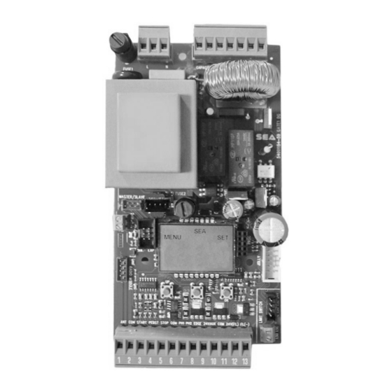
- Page 2 ® English English GATE 1 DG R2BF Sistemi Elettronici di Apertura Porte e Cancelli COMPONENTS TECHNICAL SPECIFICATIONS Control unit power supply: 230 Vac 50/60 Hz - 115Vac 50/60 Hz Absorption in stand by: 30 mA Environment temperature : -20°C +50°C...
- Page 3 English CONNECTIONS RADIO MODULE RF FIX (CNS) 24V (Red) Limit switch Closing 1 (Yellow) RF FIX 14 15 16 17 18 19 20 Receiver Limit switch Opening 1 (Green) 24Vac LIGHT LIGHTN MCL MN MOP CAPACITOR connector Max 150 mA Common (White) (Available from hardware...
- Page 4 English PROGRAMMING FAST SELF-LEARNING “Input check menu" - - - - - - DOWN DOWN Start quick programming Fast self-learning START command by radio control You can start the quick programming by holding UP for 5 s in the “Input check You can store the START button of the remote control while pressing DOWN for 5 s menu", until the motor starts.
-
Page 5: Programming Quick Start
English PROGRAMMING PROGRAMMING BUTTONS QUICK START DOWN MENU MENU LANGUAGE ITALIANO Skip this step if you do not want to program a transmitter OK to exit Press the Menu or press MENU MENU MENU button of the MENU PRESS the button of TRANSMITTERS STORED START... - Page 6 GATE 1 DG R2BF MENU FUNCTIONS TABLE MENU DESCRIPTION DEFAULT VALUE Italiano Italian English English 1 LANGUAGE Français French English Español Spanish Dutch Dutch Start Start Partial opening Partial opening External module External module Stop Stop Start Storing of a command for unlocking...
-
Page 7: Pause Time
PRESS AT THE SAME TIME FOR 5 SECONDS TO ENTER OR TO EXIT THE SPECIAL MENU DO W N SPECIAL MENU FUNCTIONS TABLE GATE 1 DG R2BF For entering into the special menu move on one of the menu and press the UP and DOWN buttons at the same time for 5 s. - Page 8 MENU SP DESCRIPTION DEFAULT VALUE Enables reading 32 ENCODER Potentiometer potentiometer with LE card Reports the current position of the potentiometer on the leaf of motor . This parameter is useful for seeing I.PAR.M1 - - - - - - - - if the potentiometer is read correctly Reports the impulses stored by the control unit when I.AP.M1...
- Page 9 MENU SP DESCRIPTION DEFAULT VALUE In case of obstacle or edge it totally reverses the movement during the Total closing. If active, the automatic reclosing will be attempted 5 times 46 CLOSING INVERSION Partial It partially reverses the direction (of Partial about 30 cm) in case of obstacle or edge or potentiometer...
- Page 10 MENU SP DESCRIPTION DEFAULT VALUE Allows repetition pushover function at a distance of 81 PERIODICAL PUSHOVER time adjustable from 0 to 8 hours at hourly intervals Opening 1 Off - 3 s Closing 1 Off - 3 s If different from Off, the motor (hydraulic) 82 MOTOR RELEASE slightly reverse its direction at the...
- Page 11 MENU SP DESCRIPTION DEFAULT VALUE Always AUX output always Power supplied In cycle AUX output active only during cycle AUX output power supplied only Opening during opening AUX output power supplied only Closing during closing AUX out put power supplied only In pause during pause Autotest...
- Page 12 MENU SP DESCRIPTION DEFAULT VALUE Photo 1 Self-test active only on photo 1 Photo 2 Self-test active only on photo 2 Photo 1 and 2 Self-test active on photo 1 and 2 Disabled Edge Self-test active only on security edge 95 FOTOTEST Self-test active on photocell 1 and Photo 1 and Edge...
- Page 13 MENU SP DESCRIPTION DEFAULT VALUE If the photocell is occupied, it reverses the movement in closing; Closing during the pause, it prevents the reclosing If active the photocell blocks the movement as long as it is busy; Opening and closing when released, opening...
-
Page 14: Maintenance Cycles
MENU SP DESCRIPTION DEFAULT VALUE Normal Normal N.C. contact Edge is active and protected by a 8K2 resistor Allows connect 8K2 Double 100 EDGE 1 protected edges Normal Edge works as a photocell protected Photo 1 10K by a 10K resistor It is possible to connect two pho- Photo 1 10K Double tocells protected by a 10K resistor... - Page 15 English WORKING TIMES SELF LEARNING The control unit is pre-set with the default settings, to start the control unit with the DEFAULT settings just keep pressed the UP and DOWN buttons at the same time power supplying the control unit the display shows the message “Init”. The DEFAULT settings are shown in the Menues table. LEARNING WITH LIMIT SWITCH (WITH OR WITHOUT ENCODER) When limit switches are mounted, the gate executes automatically the following cycle: CLOSING - OPENING - CLOSING.
-
Page 16: Function Logic
If the password has been forgotten, the only way to unlock the control unit is to contact the SEA technical assistance, which will assess whether to provide the procedure to unlock the control unit or not. - Page 17 Photocell 1 Edge DOWN Photocell 2 MENU FUNCTION TABLE CHECK GATE 1 DG R2BF INPUTS To access the Menu for input check keep pressed OK for about 5 seconds. Description MENU Description The contact must be a N.O. Contact . When activating the related...
- Page 18 English RADIO TRANSMITTER SELF LEARNING WITH RECEIVER ON BOARD OF CONTROL UNIT WARNING: Make the radio transmitters programming before you connect the antenna and insert the receiver into the special CMR connector (if available) with turned off control unit. With RF UNI and RF UNI PG module it will be possible to use both Coccinella Roll Plus transmitters and radio transmitters with fixed code.
- Page 19 English RADIO TRANSMITTER SELF LEARNING WITH RF FIX RECEIVER ON BOARD OF CONTROL UNIT WARNING: Make the radio transmitters programming before you connect the antenna and insert the receiver into the special CNS connector (if available) with turned off control unit. With the RF FIX module it will be possible to use only radio controls with fixed code.
- Page 20 English START - STOP - PEDESTRIAN START - ANTENNA - PHOTOCELL Photocell 1 and Photocell 2 Connections + = 24V Accessories COM = 0V PH1 = Photocell contact 1 PH2 = Photocell contact 2 Note 1: If the photocells are not connected, it is not necessary put a jumper between 1 2 3 4 5 6 7 8 the clamps (6 and 7 and/ou 6 and 8 of the CN1 terminal) Note 2: For self-test connect the TX to the 24VAux clamp and activate the Self-test function...
- Page 21 English ENCODER OR AMPEROMETRIC MANAGEMENT AMPEROMETRIC DEVICE FOR ELECTROMECHANICAL OPERATORS This control unit comes with an obstacle detection system working only on electromechanical operators allowing to have the reversing on obstacles and the automatic detection of the stops. Sensitivity adjustable from OFF to 99% inside the special menu.
- Page 22 English WARNING LAMP - SAFETY EDGE - 10K PHOTOCELL - BUZZER Example of flashing lamp and edge FLASHING LAMP 3W MAX 12 and 13 connections Flashing Lamp 24V (Accessories) 3W max. (Control lamp) The Flashing Lamp can be connected between the 24V clamps (Accessories) and FL (-) of CN 1.
-
Page 23: Power Supply Input
THREE-PHASE MODULE CONNECTION Power supply connector for control Motor wiring connector for control unit (230V) unit (230V) 23001158 23001158 (GATE 1 DG R2BF) 14 15 16 17 18 19 20 (GATE 1 DG R2BF) Three-phase Motor (380V~) U V W N N F COM. -
Page 24: Master-Slave Function
2) Once sure of the correct functioning connect the control unit MASTER to the control unit SLAVE through the special clamp (Code SEA 23001220). 3) Now set the control unit, which has to manage the commands and motor 1 (photocell, keyswitch, STOP, safety edge etc.) as MASTER and the other one which will move motor 2 as SLAVE. - Page 25 English SAFETY LOOP CONNECTIONS DRAWING SHOWS HOW TO EVENTUALLY CONNECT T H E M A G N E T I C L O O P 1 2 3 4 5 6 7 8 9 10 11 12 13 C1 = CONTACT OPEN C2 = CONTACT CLOSED C2 C2 12 = 24 V...
-
Page 26: Alarm Description
English ALARM DESCRIPTION Kind of alarm Solutions Signals Make sure there are no short circuits on the motor or on the Motor current failure FAILURE MOTOR control unit AUX output Make sure there are no short circuits on the wiring or on the FAILURE24 voltage failure control unit and no overloads... -
Page 27: Troubleshooting
English TROUBLE SHOOTING Advices Make sure all Safeties are turned ON Problem Found Possible Cause Solutions a) Check the connections or the jumpers on the connections of Operator doesn’t respond to a) Check the connected N.C. contacts the safety edge or of the stop and of the photocell if connected any START impulse b) Burnt fuse b) Replace the burnt fuse on the control unit... - Page 28 English Advices Make sure all Safeties are turned ON Problem Found Possible Cause Solutions a) Check menu for encoder parameters "Encoder Par" shall be from a low value +/- 10 (gate completely closed) to "Encoder a) ENCODER is not working properly if It's tot"...
-
Page 29: Maintenance
Materials handling must be made with appropriate vehicles.. WARRANTY LIMITS For the guarantee see the sales conditions on the official SEA price list. SEA reserves the right to make any required modification or change to the products and/or to this manual without any advanced notice obligation. - Page 30 5. Do not install the equipment in an explosive atmosphere. 6. SEA S.p.A. is not responsible for failure to observe Good Techniques in the construction of the locking elements to motorize, or for any deformation that may occur during use.
- Page 31 The recognized defects, whatever their nature, shall not produce any responsibility and/or damage claim on the part of the Buyer against SEA. The guarantee is in no case recognized if changes are made to the goods, or in the case of improper use, or in the case of tampering or improper assembly, or if the label affixed by the manufacturer has been removed including the SEA registered trademark No.
- Page 32 International registered trademark n. 804888 Dichiarazione di conformità Declaration of Conformity La SEA S.p.A. dichiara che, con l’installazione degli adeguati dispositivi di sicurezza e di filtraggio disturbi, il prodotto: SEA S.p.A. declares that by installing the appropriate safety equipment and noise filtering the product:...
- Page 33 Cet article a été produit suivant des procédures d'usinage strictes et il a singulièrement été testé afin de garantir les plus hauts niveaux de qualité pour votre satisfaction. Nous vous remercions d'avoir choisi SEA. Este articulo ha sido producido siguiendo rigidos procedimientos de elaboracion y ha sido probando singolarmente a fin de garantizar los mas altos inveles de calidad y vuestra satisfaccion.
- Page 34 ® Sistemi Elettronici di Apertura Porte e Cancelli International registered trademark n. 804888 Note - Notes - Note - Notas - Anmerkung...
- Page 36 ® Sistemi Elettronici di Apertura Porte e Cancelli International registered trademark n. 804888 SEA S.p.A. Zona industriale 64020 S.ATTO Teramo - (ITALY) Tel. +39 0861 588341 r.a. Fax +39 0861 588344 www.seateam.com seacom@seateam.com...
Need help?
Do you have a question about the GATE 1 DG R2BF and is the answer not in the manual?
Questions and answers