Advertisement
Fits:
2009-Current
2010-Current
REMOVE CONTENTS FROM BOX. VERIFY ALL PARTS ARE PRESENT.
READ INSTRUCTIONS CAREFULLY BEFORE STARTING INSTALLATION.
DO NOT OVER TORQUE. STANDARD OPERATING LOAD FOR TIGHTEN
BODY MOUNT NUTS & BOLTS VARIES FROM 45 TO 65 FOOT POUND.
Qty
1
1
3
Driver/left Mounting Brackets
3
Passenger/passenger Mounting Brackets
3
Driver/left Support Brackets
3
Passenger/right Support Brackets
6
6
18
(3) Passenger/Right
Mounting Brackets
Passenger/Right Support Brackets
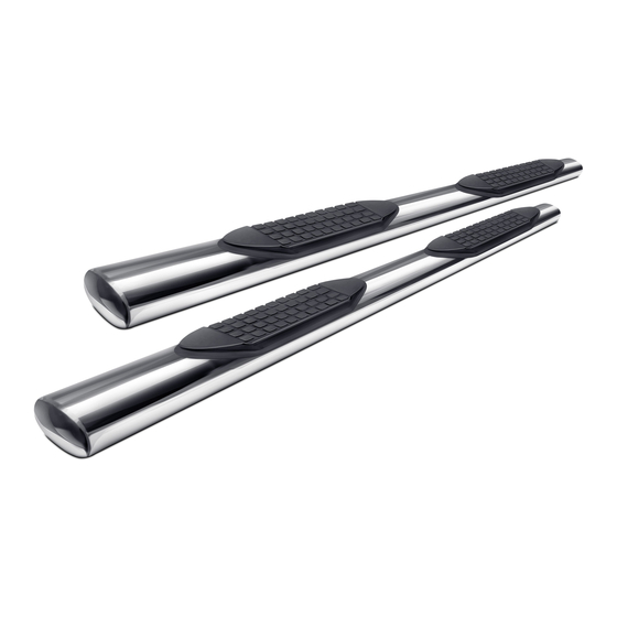
Driver/left Side Step
illustrated. Note front step
pad is slightly closer to
front end of tube
Page 1 of 7
4" Oval Nerf Bar
Part No. A1537S/B
Dodge Ram 1500 Crew Cab
Dodge Ram 2500/3500/4500/5500 Crew Cab
Part Description
Driver/Left Sidebar
Passenger/Right Sidebar
8mm Nut/Bolt Plates
8mm Plastic Retainers
8mm-1.25 x 30 Hex Bolts
Arrows show approximate location
of inserts in bottom of Sidebars
Front
PARTS LIST:
Qty
12
8mm-1.25 x 25mm Combination Hex Bolts
24
12
6
6
12
24
12
(6) 8mm Bolt x 8mm Nut
Plates
(6) Plastic Retainers
(3) Driver/Left
Mounting Bracket
www.TrailFX.com
Cutting Not
60-180 min
Required
support@trailfx.com
1 866 638 4870
POLISHED STAINLESS STEEL – LIMITED LIFETIME
POWDER COATED BLACK – 3 YEARS
Part Description
8mm x 24mm x 2mm Flat Washers
8mm Lock Washers
8mm Hex Nuts
8mm Nylon Lock Nuts
6mm x 25mm Hex Bolts
6mm x 22mm x 2mm Flat Washers
6mm Nylon Lock Nuts
(3) Driver/Left Support
Brackets
Drilling is
Required
Rev 031318
Advertisement
Table of Contents

Subscribe to Our Youtube Channel
Related Manuals for TrailFX A1537S


Summary of Contents for TrailFX A1537S
- Page 1 4" Oval Nerf Bar Part No. A1537S/B Fits: 2009-Current Dodge Ram 1500 Crew Cab 2010-Current Dodge Ram 2500/3500/4500/5500 Crew Cab Cutting Not Drilling is 60-180 min Required Required REMOVE CONTENTS FROM BOX. VERIFY ALL PARTS ARE PRESENT. support@trailfx.com READ INSTRUCTIONS CAREFULLY BEFORE STARTING INSTALLATION.
- Page 2 INSTALLATION PROCEDURE Starting at the driver side-front of the vehicle, remove the sealing tape covering the factory holes in the side of the inner panel, (Figure 1). Front (Fig 1) 2009-mid 2015 Driver/Left front mounting location (No factory holes...
- Page 3 Thread (1) 8mm Plastic Retainer onto the threaded end and down tight against the body panel, (Figure 5). NOTE: The Plastic Retainer is designed to keep the Bolt/Nut Plate from falling into the body panel and to aid in Bracket installation.
- Page 4 Models with factory threaded inserts: Attach the driver side Front Bracket directly to the threaded inserts with (2) 8mm x 30mm Hex Bolts, (2) 8mm Lock Washers and (2) 8mm Flat Washer, (Figures 9 & 10). Leave hardware loose.
- Page 5 Move to the rear location, (Figure 15). Repeat Steps 2—4 to install the rear Brackets, (Figure 16). NOTE: The cradles on the front, center and rear Brackets must all face forward. Rear Rear (Fig 16) Driver/Left rear Brackets installed...
- Page 6 Properly level and adjust the Sidebar and fully tighten all hardware. 2009-10 models requiring drilling for driver side Support Brackets: Make sure the Sidebar is level to the vehicle. Adjust and tighten all mounting hardware. Line up the slots on the Support Brackets with the back of the pinch weld. Mark the location of the slots onto the pinch weld.
- Page 7 6. Product not installing properly. Ensure make model year, cab length and bed size of your vehicle is listed in the application. All installation steps are followed correctly. Check out these other TrailFX Products!! www.TrailFX.com Keystone Automotive Operations Inc. (KAO) warrants this product to be free of defects in material and workmanship at the time of purchase by the original retail consumer.
Need help?
Do you have a question about the A1537S and is the answer not in the manual?
Questions and answers