
Subscribe to Our Youtube Channel
Related Manuals for baltur BT 350 DSG


Summary of Contents for baltur BT 350 DSG
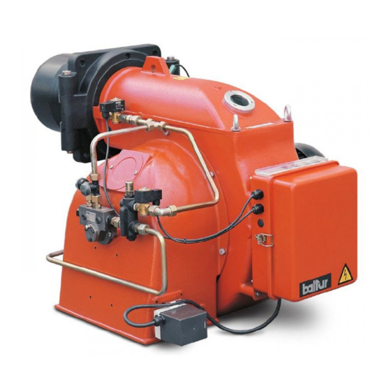
- Page 1 Manual user instructions. BT 350 DSG TWO-STAGE DIESEL BURNER ISTRUZIONI ORIGINALI (IT) 98318_201204...
-
Page 3: Table Of Contents
(International Tel. ++39.051.684.37.11 - Fax ++39.051.683.06.86) The system power supply must be disconnected before starting working. If the works are not carried out correctly it is possible to http://www.baltur.it - http://www.baltur.com - E-MAIL info@baltur.it cause dangerous accidents. Declaration of Conformity We declare that our products BPM...;... - Page 4 In such case get in touch with only qualifi ed technicians. Any c) Carry out a check on combustion to ensure the production of no- product repairs must only be carried out by BALTUR authorised assi- xious or polluting unburnt gases does not exceed limits permitted stance centres using only original spare parts.
- Page 5 WARNING NOTES FOR THE USER HOW TO USE THE BURNER SAFELY Special warning notes when using gas ELECTRICAL SUPPLY • Have qualifi ed technicians check the following: • The equipment is electrically safe only when it is correctly connected to an effi cient ground connection carried out in accordance with current safety a) that the feed line and the train comply with current law and regulations.
-
Page 6: Technical Specifications
TECHNICAL SPECIFICATIONS BT 350 DSG MIN Kg/h FLOW RATE MAX Kg/h HEATING CAPACITY 1364 MIN kW 4151 MAX kW FUEL VISCOSITY DIESEL 1.5°E - 20°C FUEL FAN MOTOR 9.2 kW - 2910 r.p.m. 50Hz IGNITION TRANSFORMER 14 kV - 30mA - 230V - 50Hz... - Page 7 OVERALL DIMENSIONS MOD. E Ø FØ BT 350 DSG 1050 1960 350 ÷ 560 400÷540 M 20 OPERATING RANGE 5 / 22 98318_201204...
-
Page 8: Preliminary Remarks For A Proper Installation
FIXING THE BURNER TO THE BOILER PRELIMINARY REMARKS FOR A PROPER INSTALLATION Before proceeding with the installation make sure that: 1) The chimney (cross section and height) complies with the boiler manufacturer’s instructions and legal provisions. 2) Where a refractory lining needs to be made for the combustion chamber (if the type of boiler requires it) then, it is necessary to make it according to the specific instructions of the boiler manufacturer. -
Page 9: Electrical Connections
ELECTRICAL CONNECTIONS The auxiliary pump should be installed as near as possible to the fuel to be sucked. The electrical connections to the burner are minimal. It is advisable The head should meet the requirements of the system used. to make all electrical connections with flexible electrical wire. Electric lines should be at an adequate distance from hot parts. - Page 10 PIPELINE TABLE FOR BURNERS MODEL BT 350 DSG GRAVITY FEED SYSTEM 1 Tank 6 Suction pipe 2 Feeding pipe 7 Burner return pipe 3 Wire-net filter 8 Automatic fuel interception device at burner shut off 4 Pump 9 One-way valve...
-
Page 11: Operation Description
FEED SYSTEM HYDRAULIC DIAGRAM FOR SEVERAL DIESEL FUEL OR HEAVY OIL BURNERS WITH MAXIMUM NOMINAL VISCOSITY (5 °E at 50 °C) 1 - Main tank The oil recovery tanks (diameter ~ 150 - height ~ 400) should be installed as near as possible to the burner and should be about 2 - Filter 0,5 m higher with respect to the burner’s pump. - Page 12 If, during operation the flame is lacking for any reason, the photocell pressure of 16 bar using diesel fuel. Bear also in mind that as the activates immediately (one second) and stops the relay supply and burner is working with only the first flame activated, the first nozzle fuel supply corresponds to the values indicated on the turns it off.
-
Page 13: Ignition And Adjustment
FIRST FILLING UP OF PIPELINES d) The exhaust of combustion products takes place freely (boiler and chimney gate valves open). After making sure that the protective plastic caps inside the pump e) Make sure that the burner head penetrates into the combustion fittings have been removed, proceed as follows: chamber according to the instructions of the boiler manufacturer. -
Page 14: Adjusting The Distance Between Disk And Nozzle - Adjusting The Air On The Combustion Head
min. 10% to max. 13% with a smoke number not exceeding possible needed for safe ignition, even in the most difficult 2 (Bacharach scale). We remind you that for the first flame circumstances. is preferable to limit the quantity of air to the lowest amount possible needed for safe ignition, even in the most difficult CHECKS circumstances. -
Page 15: Maintenance
Assistance Service to repair the fault. low capacity is used for a gentle ignition, which is essential for boilers with a pressurised combustion chamber and also very MAINTENANCE useful for normal boilers with depression combustion chamber. The ignition start/stop command is subject to the usual operating The burners do not require particular servicing. -
Page 16: Troubleshooting
TROUBLESHOOTING TYPE OF PROBLEM POSSIBLE CAUSE SOLUTION The burner goes into lock-out with the flame 1) Photocell severed or fouled with smoke 1) Clean or replace it on (Red lamp on). The fault is in the flame 2) Insufficient draft 2) Check all the smoke ducts in the boiler and in control device. - Page 17 TYPE OF PROBLEM POSSIBLE CAUSE SOLUTION Defective flame with presence of 1) Atomising pressure too low 1) Restore it at the required rating sparks 2) Too much combustion air 2) Reduce combustion air flow 3) Inefficient nozzle, either fouled or worn 3) Clean or replace 4) Water in the fuel 4) Drain it from the tank using a suitable pump.
- Page 18 LAYOUT DIAGRAM FOR DISK-NOZZLE-ELECTRODES THREE NOZZLE ATOMISER UNIT MOD. BT 350 DSG 3÷4 DIAGRAM ILLUSTRATING PRINCIPLE OF AIR CONTROL WRONG ADJUSTMENT Combustion head Air passageway wide open Air combustion inlet Knobs for controlling and fastening gate valve mostly closed the combustion head...
-
Page 19: Baltur Pump Model Bt
BALTUR PUMP MODEL BT..1/4" vacuum gauge connection Suction Return Pump plate Delivery (nozzle) Pump pressure pre-setting (20 ÷ 22 bar) 1/4" Pressure gauge connection Heating element seat Suction 1/4" vacuum gauge connection Return Delivery (nozzle) Pump pressure pre-setting (20 ÷ 22 bar) 1/4"... -
Page 20: Nozzle Flow-Rate Table For Diesel Fuel
NOZZLE FLOW-RATE TABLE FOR DIESEL FUEL Pump pressure Nozzle Nozzle Nozzle output flow-rate G.P.H. G.P.H. 0.40 1.27 1.36 1.44 1.52 1.59 1.67 1.73 1.80 1.86 1.92 1.98 2.04 2.10 2.15 2.20 0.40 0.50 1.59 1.70 1.80 1.90 1.99 2.08 2.17 2.25 2.33 2.40... - Page 21 MOTOR “CONECTRON LKS 160” SETTING FOR AIR SHUTTER COMMAND IN FIRST FLAME POSITION ADJUSTABLE CAMS REFERENCE INDEX FLAME AIR ADJUSTING CAM (60°) III UNUSED CAM ( . . . °) FLAME AIR ADJUSTING CAM (20°) IV 2 FLAME VALVE ACTUATING CAM (40°) SETTING OF MOTOR “CONECTRON LKS 160”...
-
Page 22: Wiring Diagram
WIRING DIAGRAM 20 / 22 98318_201204... - Page 23 21 / 22 98318_201204...
- Page 24 Baltur S.p.A. Via Ferrarese, 10 44042 Cento (Fe) - Italy Tel. +39 051-6843711 Fax: +39 051-6857527/28 www.baltur.it info@baltur.it - The information contained in this catalogue is not binding. The manufacturer reserves the right to change the technical data and any other data it contains.
Need help?
Do you have a question about the BT 350 DSG and is the answer not in the manual?
Questions and answers