Table of Contents
Advertisement
Available languages
Available languages
Quick Links
ITALIANO
Manuale istruzioni per l'installazione, l'uso e
la manutenzione
Installation, use and maintenance instruction
ISTRUZIONI ORIGINALI (IT)
ORIGINAL INSTRUCTIONS (IT)
TWO-STAGE PROGRESSIVE / MODULATING DIESEL BURNERS
IT
EN
manual
BRUCIATORI DI GASOLIO BISTADIO PROGRESSIVO /
GI 350 DSPG
GI 420 DSPG
GI 510 DSPG
0006080098_201803
MODULANTE
Advertisement
Table of Contents

Subscribe to Our Youtube Channel
Related Manuals for baltur GI 350 DSPG


Summary of Contents for baltur GI 350 DSPG
- Page 1 BRUCIATORI DI GASOLIO BISTADIO PROGRESSIVO / MODULANTE TWO-STAGE PROGRESSIVE / MODULATING DIESEL BURNERS ITALIANO GI 350 DSPG Manuale istruzioni per l'installazione, l'uso e la manutenzione GI 420 DSPG Installation, use and maintenance instruction manual GI 510 DSPG ISTRUZIONI ORIGINALI (IT)
-
Page 3: Table Of Contents
ITALIANO ITALIANO SOMMARIO Avvertenze per l'uso in condizioni di sicurezza ..............................3 Caratteristiche tecniche ...................................... 6 Materiale a corredo ...................................... 7 Targa identificazione bruciatore ................................... 7 Caratteristiche tecnico funzionali ................................. 8 Caratteristiche costruttive .................................... 8 Campo di lavoro ......................................8 Descrizione componenti ....................................9 Dimensioni di ingombro .....................................10 Applicazione del bruciatore alla caldaia ................................ - Page 4 ITALIANO DICHIARAZIONE DI CONFORMITÀ CE0085: DVGW CERT GmbH, Josef-Wirmer Strasse 1-3-53123 Bonn (D) Dichiariamo che i nostri bruciatori ad aria soffiata di combustibili luquidi, gassosi e misti, domestici e industriali, serie: BPM...; BGN…; BT…; BTG…; BTL…; TBML...; Comist…; GI…; GI…Mist; Minicomist…; PYR…; RiNOx…; Spark...; Sparkgas...; TBG..;TBL..; TS…;...
-
Page 5: Avvertenze Per L'uso In Condizioni Di Sicurezza
ITALIANO AVVERTENZE PER L'USO IN CONDIZIONI DI compresi) le cui capacità fisiche, sensoriali o mentali siano ridotte, oppure con mancanza di esperienza o di conoscenza. SICUREZZA • l'uso dell'apparecchio è consentito a tali persone solo nel caso in cui possano beneficiare, attraverso l'intermediazione di una SCOPO DEL MANUALE persona responsabile, di informazioni relative alla loro sicurezza, Il manuale si propone di contribuire all'utilizzo sicuro del prodotto... - Page 6 • Prima di avviare il bruciatore e almeno una volta all’anno, far • L’eventuale riparazione dei prodotti dovrà essere effettuata effettuare da personale professionalmente qualificato le seguenti solamente da un centro di assistenza autorizzato da BALTUR o dal operazioni: suo distributore locale, utilizzando esclusivamente ricambi originali.
- Page 7 ITALIANO RISCHI RESIDUI - Allorché si decida di non utilizzare l’apparecchio per un • Nonostante l'accurata progettazione del prodotto, nel rispetto certo periodo é opportuno spegnere l’interruttore elettrico di delle norme cogenti e delle buone regole nell'impiego corretto alimentazione a tutti i componenti dell’impianto che utilizzano possono permanere dei rischi residui.
-
Page 8: Caratteristiche Tecniche
ITALIANO CARATTERISTICHE TECNICHE MODELLO GI 350 DSPG GI 420 DSPG GI 510 DSPG Kg/h PORTATA TERMICA MINIMA Kg/h PORTATA TERMICA MASSIMA POTENZA TERMICA MINIMA 1581 1840 2430 POTENZA TERMICA MASSIMA 4743 5522 6500 mg/kWh ³) EMISSIONI Classe 1 Classe 1 Classe 1 VISCOSITÁ... -
Page 9: Materiale A Corredo
ITALIANO MATERIALE A CORREDO MODELLO GI 350 DSPG GI 420 DSPG GI 510 DSPG FLANGIA ATTACCO BRUCIATORE GUARNIZIONE ISOLANTE PRIGIONIERI N°4 - M20 N°6 - M20 N°6 - M20 DADI ESAGONALI N°4 - M20 N°6 - M20 N°6 - M20 RONDELLE PIANE N°4 Ø... -
Page 10: Caratteristiche Tecnico Funzionali
• Controllo della presenza fiamma tramite fotoresistenza. secondo normativa europea EN298. CAMPO DI LAVORO GI 420 DSPG GI 510 DSPG GI 1000 DSPG GI 350 DSPG GI MIST510 DSPGM GI MIST 350 DSPGM GI MIST 420 DSPGM GI MIST 1000 DSPGM mbar... -
Page 11: Descrizione Componenti
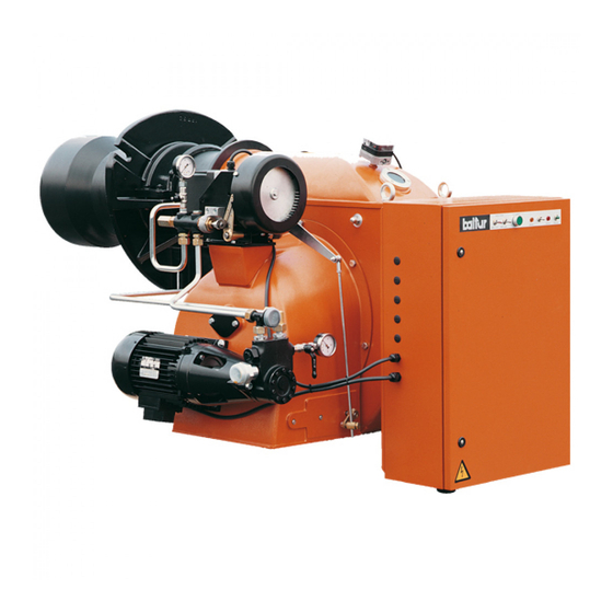
ITALIANO DESCRIZIONE COMPONENTI Pompa combustibile liquido Pressostato aria Fotoresistenza Vite di regolazione aria alla testa di combustione Regolatore di pressione ritorno ugello Modulatore regolazione aria - combustibile Quadro elettrico Motore pompa Flangia attacco bruciatore Guarnizione Testa di combustione Motore ventola Elettromagnete Targa identificazione bruciatore 9 / 40... -
Page 12: Dimensioni Di Ingombro
ITALIANO DIMENSIONI DI INGOMBRO 60° GI 350 GI 420 / 510 Modello GI 350 DSPG 1345 1900 GI 420 DSPG 1345 1040 2030 GI 510 DSPG 1345 1040 2030 Modello D min D max E Ø F Ø L min... -
Page 13: Applicazione Del Bruciatore Alla Caldaia
ITALIANO APPLICAZIONE DEL BRUCIATORE ALLA GI 420 - 510 ... CALDAIA Per movimentare il bruciatore si consiglia di agganciare ai golfari una adeguata attrezzatura di sollevamento come da figura. Fissare il bruciatore al portellone caldaia nel seguente modo: • Posizionare sul cannotto la guarnizione isolante (13) •... -
Page 14: Impianto Di Alimentazione Con Combustibile Liquido
ITALIANO IMPIANTO DI ALIMENTAZIONE CON aspirazione. Solo i tubi di ritorno possono confluire in un’unico tubo di sezione COMBUSTIBILE LIQUIDO adeguata per raggiungere il serbatoio del combustibile. La tubazione di aspirazione dovrà essere disposta in salita verso il La pompa del bruciatore deve ricevere il combustibile da un adatto bruciatore, per evitare accumulo di eventuali bolle di gas. - Page 15 ITALIANO SCHEMA IDRAULICO DI PRINCIPIO ALIMENTAZIONE PER UNO O PIÚ BRUCIATORI A DUE STADI O MODULANTI CON VISCOSITÁ NOMINALE MASSIMA (5° E A 50° C) I serbatoi di recupero combustibile (diametro ~ 150 mm - altezza ~ 400 mm) devono essere installati il più vicino possibile al bruciatore ad una quota superiore di 0,5 m rispetto alla pompa dello stesso.
-
Page 16: Collegamenti Elettrici
ITALIANO COLLEGAMENTI ELETTRICI • Tutti i collegamenti devono essere eseguiti con filo elettrico flessibile. • Rispettare le normative nazionali ed europee applicabili (es. EN 60335-1/EN 50165) relative alla sicurezza elettrica; • Connettere i dispositivi, senza opzione N o N1, all’alimentazione elettrica rispettando la polarità... -
Page 17: Descrizione Del Funzionamento Adue Stadi Progressivi
ITALIANO DESCRIZIONE DEL FUNZIONAMENTO A in caldaia lo consente, viene attivato il servomotore di regolazione, determinando un aumento graduale dell’erogazione di combustibile DUE STADI PROGRESSIVI e aria comburente fino a raggiungere l’erogazione massima a cui il bruciatore è stato regolato. Si dice funzionamento a due stadi progressivi, in quanto il passaggio L’aumento dell’erogazione di combustibile viene determinato dal disco dal primo stadio (potenza minima) al secondo stadio (potenza... - Page 18 ITALIANO Riabbassandosi la temperatura (pressione se caldaia a vapore) al di sotto del valore di intervento del dispositivo di arresto, il bruciatore ritorna ad accendersi come precedentemente descritto. Nel normale funzionamento il termostato di caldaia o pressostato di secondo stadio applicato alla caldaia rileva le variazioni di richiesta ed automaticamente provvede ad adeguare l’erogazione di combustibile e di aria comburente attraverso il servomotore con rotazione in aumento oppure in diminuzione, adeguando la quantità...
-
Page 19: Descrizione Del Funzionamento Amodulazione
ITALIANO DESCRIZIONE DEL FUNZIONAMENTO A toglie corrente al trasformatore e mantiene il bruciatore in funzione alla portata minima. MODULAZIONE Se la sonda di temperatura o pressione vapore è regolata ad un valore di temperatura o pressione superiore a quella esistente in Si dice funzionamento a modulazione, in quanto il passaggio caldaia, viene attivato il servomotore di regolazione, determinando un dal primo stadio (potenza minima) al secondo stadio (potenza... - Page 20 ITALIANO Al riabbassarsi della temperatura o pressione in caldaia la sonda di modulazione rileva una variazione di carico della caldaia ed automaticamente richiede l’adeguamento dell’erogazione di combustibile e aria comburente al servomotore. Con questa manovra il bruciatore modula l'erogazione di combustibile e aria comburente secondo la quantità...
-
Page 21: Accensione E Regolazione
ITALIANO ACCENSIONE E REGOLAZIONE posizione “O” (aperto) e dare corrente alla linea elettrica a cui il bruciatore è collegato. • Verificare che la tensione della linea elettrica corrisponda a quella • Premendo manualmente sulle sedi mobili dei relativi teleruttori, richiesta dal costruttore e, che tutti i collegamenti elettrici realizzati verificare che il motore del ventilatore e, se presente, della pompa sul posto, siano eseguiti come da nostro schema elettrico. - Page 22 ITALIANO • Con bruciatore in funzione alla potenza minima, si provvede a regolare l’aria agendo sulle viti registrabili, in corrispondenza del punto di contatto con la leva che trasmette il movimento alla serranda di regolazione dell’aria, così da ottenere una buona combustione.
- Page 23 ITALIANO • Controllare che la regolazione aria / combustibile sia corretta, • La fiamma del bruciatore deve spegnersi. stringere le viti di bloccaggio delle viti regolazione modulazione. • Mantenendo la fotoresistenza oscurata, il bruciatore si riaccende • Verificare ora il corretto funzionamento automatico della ma, la fotoresistenza non vede la luce e, nel tempo determinato dal modulazione portando l’interruttore (S4) in posizione “AUT”...
-
Page 24: Regolazione Aria Sulla Testa Di Combustione
ITALIANO REGOLAZIONE ARIA SULLA TESTA DI COMBUSTIONE REGOLAZIONE NON CORRETTA La testa di combustione è dotata di un dispositivo di regolazione che permette di aprire o chiudere il passaggio dell’aria tra il disco e la testa. Chiudendo il passaggio si riesce così ad ottenere, un’elevata pressione a monte del disco anche con le basse portate. -
Page 25: Schema Di Regolazione Testa Di Combustione E Distanza Disco Elettrodi
ITALIANO SCHEMA DI REGOLAZIONE TESTA DI COMBUSTIONE E DISTANZA DISCO ELETTRODI Modello GI 420 DSPG / 16,5 46,5 DSPN GI 350 DSPG / 31,5 DSPN GI 510 DSPG / DSPN PARTICOLARI POMPA SCHEMA COLLEGAMENTO POMPA HP 1 - Aspirazione 2 - Attacco vuotometro 1/4"... -
Page 26: Particolare Motore Sqm 10 E Sqm 20 Di Comando Modulazione Per Regolazione Camme
ITALIANO PARTICOLARE MOTORE SQM 10 E SQM 20 DI COMANDO MODULAZIONE PER REGOLAZIONE CAMME Per modificare la regolazione delle 3 cammes utilizzate, si agisce sui 3 4 5 6 7 rispettivi anelli (I - II - III) di colore rosso. Spingendo con forza sufficiente, nel senso voluto, ogni anello (rosso) può... -
Page 27: Apparecchiatura Di Controllo E Comando Lal 1
ITALIANO APPARECCHIATURA DI CONTROLLO E COMANDO LAL 1.. LAL 1... t 1 6 t 1 1 1 6 1 7 1 8 1 1 1 0 1 ( 3 ) Q R B 1 E K 2 B V 2 B V 1 Q R C 1 . - Page 28 ITALIANO LEGENDA Contatto commutatore di fine corsa per la posizione APERTA della serranda aria Segnalazione e distanza di un arresto di blocco Relè principale (relè di lavoro} con contatti ar... Fusibile dell’apparecchio Ponte elettrico (sull'innesto del comando del bruciatore) Relè di blocco con contatti br..BV...
- Page 29 ITALIANO FUNZIONAMENTO Gli schemi precedenti illustrano sia il circuito di collegamento che il programma di controllo dai segnali di ingresso ammessi necessari alla sezione di controllo del comando del bruciatore e al relativo circuito di supervisione della fiamma. In assenza dei necessari segnali di ingresso, il comando del bruciatore interrompe la sequenza di avvio nei punti contrassegnati dai simboli avviando il blocco qualora richiesto dalle norma di sicurezza applicabili.
- Page 30 ITALIANO Tempo di accensione corto, a condizione che Z sia collegato al morsetto 16; quindi conferma combustibile sul morsetto 18. Tempo di sicurezza, Alla fine del tempo di sicurezza deve comparire un segnale di fiamma al morsetto 22 dell'amplificatore e il segnale deve persistere sino ad un arresto di regolazione;...
- Page 31 ITALIANO In linea di principio, in caso di interruzione di qualsiasi natura, l'afflusso Programma di comando in caso di interruzione e indicazione della posizione di combustibile è immediatamente interrotto. Nello stesso tempo, il di interruzione programmatore resta immobile, come l'indicatore di posizione dell'interruttore. Il simbolo visibile sul disco di lettura dell'indicatore indica il tipo di anomalia: Nessun avviamento, a causa della mancata chiusura di un contatto (vedi anche Condizioni indispensabili per l'avviamento del bruciatore) o arresto...
- Page 32 ITALIANO COLLEGAMENTI ELETTRICI Bruciatore a due stadi L... (t3´/t3n) (t3) 10 8 13 12 Comando di potenza da regolare ON / OFF. Durante gli arresti di funzionamento la serranda aria viene chiusa. t3´ 100% min. 0... 7153a09/0498 Comando segnale del servomotore SA a filo singolo. (Servomotore SA tipo SQN3...
- Page 33 ITALIANO DIAGRAMMA DEL Uscite di comando PROGRAMMATORE t3´ VIII XIII Indicazione di posizione dell’interruzione LEGENDA TEMPI Tempo di preventilazione con serrande aria aperta. Tempo di sicurezze. Tempo di pre-accensione corto (trasformatore di accensione sul morsetto 16). t3' Tempo di pre-accensione lungo (trasformatore di accensione sul morsetto 15). t3n Tempo di post-acoensione (trasformatore di accensione sul morsero 15).
-
Page 34: Manutenzione
ITALIANO MANUTENZIONE Effettuare almeno una volta all’anno e comunque in conformità alle norme vigenti, l’analisi dei gas di scarico della combustione verificando la correttezza dei valori di emissioni. • Pulire le serrande aria, il pressostato aria con presa di pressione ed il relativo tubo se presenti. -
Page 35: Tempi Di Manutenzione
ITALIANO TEMPI DI MANUTENZIONE Descrizione particolare Azione da eseguire Gasolio TESTA DI COMBUSTIONE CONTROLLO VISIVO, INTEGRITA' CERAMICHE, SMERIGLIATURA ESTREMITA', ELETTRODI ANNUO VERIFICARE DISTANZA, VERIFICARE CONNESSIONE ELETTRICA DISCO FIAMMA CONTROLLO VISIVO INTEGRITA' EVENTUALI DEFORMAZIONI, PULIZIA ANNUO COMPONENTI TESTA COMBUSTIONE CONTROLLO VISIVO INTEGRITA' EVENTUALI DEFORMAZIONI, PULIZIA ANNUO UGELLI COMBUSTIBILE LIQUIDO SOSTITUZIONE... -
Page 36: Vita Attesa
ITALIANO VITA ATTESA La vita attesa dei bruciatori e dei relativi componenti dipende molto dal tipo di applicazione su cui il bruciatore è installato, dai cicli della potenza erogata, dalle condizioni dell’ambiente in cui si trova, dalla frequenza e modalità di manutenzione, ecc. ecc. Le normative relative ai componenti di sicurezza, prevedono una vita attesa di progetto espressa in cicli e/o anni di funzionamento. -
Page 37: Istruzioni Per L'accertamento Delle Cause Di Irregolarità Nel Funzionamento E La Loro Eliminazione
ITALIANO ISTRUZIONI PER L'ACCERTAMENTO DELLE CAUSE DI IRREGOLARITÀ NEL FUNZIONAMENTO E LA LORO ELIMINAZIONE IRREGOLARITÁ POSSIBILE CAUSA RIMEDIO L'apparecchio va in "blocco" con la fiamma Fotoresistenza interrotta o sporca Pulire o sostituire. (lampada rossa accesa) il guasto è di fumo. Controllare tutti i passaggi dei fumi circoscritto al dispositivo di controllo fiamma. - Page 38 ITALIANO IRREGOLARITÁ POSSIBILE CAUSA RIMEDIO Fiamma difettosa con presenza di faville. Pressione di polverizzazione troppo Ripristinarla al valore previsto. bassa. Diminuire l’aria comburente Eccesso di aria comburente. Pulire o sostituire. Ugello inefficiente perché sporco o Scaricare l'acqua dalla cisterna logoro. servendosi di una pompa adatta.
-
Page 39: Schemi Elettrici
ITALIANO SCHEMI ELETTRICI 37 / 40 0006080098_201803... - Page 40 ITALIANO 38 / 40 0006080098_201803...
- Page 41 ITALIANO 39 / 40 0006080098_201803...
- Page 42 ITALIANO APPARECCHIATURA FOTORESISTENZA / ELETTRODO DI IONIZZAZIONE / FOTOCELLULA UV RELE’ TERMICO RELE’ TERMICO POMPA FU1÷4 FUSIBILI SPIA DI FUNZIONAMENTO SPIA DI BLOCCO LAMPADA CARICAMENTO SERBATOIO “CONTATTORE MOTORE POMPA“ “CONTATTORE TRIANGOLO“ CONTATTORE ESTERNO CONTATTORE DI LINEA TEMPORIZZATORE MOTORE VENTOLA MOTORE POMPA “REGOLATORE ELETTRONICO“...
- Page 43 ENGLISH ENGLISH INDEX Instructions for use in safe conditions ................................4 Technical specifications ...................................... 6 Supplied material ......................................7 Burner identification plate .................................... 7 Technical functional characteristics ................................8 Design characteristics ....................................8 Operating range ......................................8 Component description ....................................9 Overall dimensions ....................................10 Burner connection to the boiler ..................................
- Page 44 ENGLISH DECLARATION OF CONFORMITY CE0085: DVGW CERT GmbH, Josef-Wirmer Strasse 1-3-53123 Bonn (D) We hereby declare under our own responsibility, that our domestic and industrial blown air burners fired by gas, oil and dual fuel, series: BPM...; BGN…; BT…; BTG…; BTL…; TBML...; Comist…; GI…; GI…Mist; Minicomist…; PYR…; RiNOx…; Spark...; Sparkgas...; TBG..;TBL..; TS…;...
- Page 45 ENGLISH INSTRUCTIONS FOR USE IN SAFE the device. • This appliance should only be used for the purpose it has been CONDITIONS designed for. Any other use is to be considered improper and therefore dangerous. PURPOSE OF THE MANUAL • The equipment must be installed in accordance with current The manual purpose is to contribute to the safe use of the product, regulations, following the manufacturer’s instructions and by indicating the conduct and behaviour required to prevent alterations...
- Page 46 Contact only qualified personnel. - Check the regulation and safety devices are working properly. • Any product repairs must only be carried out by BALTUR authorised - Check for the correct operation of the combustion products assistance centres or its local retailer using only original spare exhaust duct.
- Page 47 ENGLISH RESIDUAL RISKS - if unsheathed at least FG7 or FROR • In spite of the accurate product planning according to the regulations in force, residual risks may still be present during correct use. They are indicated on the burner by means of specific Pictograms. CAUTION Mechanical parts in motion.
- Page 48 ENGLISH TECHNICAL SPECIFICATIONS MODEL GI 350 DSPG GI 420 DSPG GI 510 DSPG Kg/h MINIMUM THERMAL CAPACITY Kg/h MAXIMUM THERMAL CAPACITY MINIMUM THERMAL POWER 1581 1840 2430 MAXIMUM THERMAL POWER 4743 5522 6500 mg/kWh ³) EMISSIONS Class 1 Class 1...
- Page 49 ENGLISH SUPPLIED MATERIAL MODEL GI 350 DSPG GI 420 DSPG GI 510 DSPG BURNER CONNECTION FLANGE INSULATING SEAL STUD BOLTS No. 4 - M20 No. 6 - M20 No. 6 - M20 HEXAGONAL NUTS No. 4 - M20 No. 6 - M20 No.
- Page 50 European standard EN298. • Flame presence control with photocell. OPERATING RANGE GI 420 DSPG GI 510 DSPG GI 1000 DSPG GI 350 DSPG GI MIST510 DSPGM GI MIST 350 DSPGM GI MIST 420 DSPGM GI MIST 1000 DSPGM mbar kWx1000...
- Page 51 ENGLISH COMPONENT DESCRIPTION Liquid fuel pump Air pressure switch Photoresistor Screw for regulation of the air supply to the combustion head Nozzle return pressure regulator Air/fuel adjustment modulator Electrical panel Pump motor Burner connection flange Seal Combustion head Fan motor Electromagnet Burner identification plate 9 / 40...
- Page 52 ENGLISH OVERALL DIMENSIONS 60° GI 350 GI 420 / 510 Model GI 350 DSPG 1345 1900 GI 420 DSPG 1345 1040 2030 GI 510 DSPG 1345 1040 2030 Model D min D max E Ø F Ø L min L max...
- Page 53 ENGLISH BURNER CONNECTION TO THE BOILER GI 420 - 510 ... For the handling of the burner, it is recommended to use a suitable hoisting equipment to be anchored to the eyebolts shown in figure. Anchor the burner to the boiler door as follows: •...
- Page 54 ENGLISH LIQUID FUEL SUPPLY SYSTEM possible formation of gas bubbles. Where more burners are installed in one boiler room, it is essential The burner pump must receive the fuel from a suitable supply circuit that every burner has its own suction pipe. featuring an auxiliary pump which may feature a pressure regulator Heat-insulate the suction and return pipes to prevent hazardous fuel adjustable from 0.5 to 3 bar.
- Page 55 ENGLISH HYDRAULIC DRAWING OF SUPPLY FOR ONE OR MORE TWO-STAGE OR MODULATING BURNERS WITH MAXIMUM NOMINAL VISCOSITY (5°E AT 50°C) The fuel recovery tanks (diameter ~ 150 mm - height ~ 400 mm) must be installed as close as possible to the burner at 0.5 m above the burner pump.
- Page 56 ENGLISH ELECTRICAL CONNECTIONS • It is advisable to make all connections with flexible electric wire. • Observe applicable national and European Standards (e.g. EN 60335-1/EN 50165) regarding electrical safety. • Connect the devices, without option N or N1, to the power supply respecting the phase-neutral polarity of the mains.
- Page 57 ENGLISH DESCRIPTION OF PROGRESSIVE TWO- upon the first ignition, to work on the screws that change the profile of the fuel /air regulation control disk. STAGE OPERATION The increase of fuel supply until maximum capacity is determined by the return pressure regulator that reaches a maximum pressure of The term two-stage progressive operation means that transition 18÷20 bar if the pump pressure is 20÷22 bar.
- Page 58 ENGLISH As temperature (or pressure for steam boilers) drops below the shut- down device's set point, the burner turns on as described above. During normal operation the second stage boiler thermostat or pressure switch applied to the boiler detects variations in demand and automatically adapts fuel and combustion air flows through the servomotor with increasing or decreasing rotation, adjusting the amount of heat required by the boiler.
- Page 59 ENGLISH MODULATION OPERATION DESCRIPTION of the return pressure regulator spring and thus an increase in pressure on the system return. The term modulation operation means that transition from the first In order to obtain a proportional increase of fuel and air, it is necessary, stage (minimum power) to the second stage (maximum power) and upon the first ignition, to work on the screws that change the profile of vice versa, is progressive in terms of both amount of combustion air...
- Page 60 ENGLISH When the temperature or pressure in the boiler decreases, the modulation probe detects a variation in boiler load and automatically requests the fuel and combustion air supply regulation to the servomotor. With this procedure the burner changes the fuel and combustion air supply according to the amount of heat required by the boiler.
- Page 61 ENGLISH STARTING UP AND REGULATION measures the working pressure of the pump, indicates a slight pressure. The presence of low pressure in the circuit confirms that • Check that thee voltage on the mains meets the manufacturer filling up has taken place. requirements and that all electrical connections made at the •...
- Page 62 ENGLISH • With the burner in minimum power function, adjust the air flow working on the adjustable screws, at the mating point with the lever transmitting the movement to the air regulation damper, as to obtain a good combustion. It is better if the amount of air for minimum power is slightly reduced in order to ensure a perfect ignition even in the most critical conditions.
- Page 63 ENGLISH • Make sure that the air/fuel regulation is correct, tighten the locking screws of the modulation adjustment screws. • Now check that the modulation system is operating correctly by turning the (S4) switch to “AUT” and the (S5) switch to “O”. •...
- Page 64 ENGLISH AIR REGULATION ON THE COMBUSTION HEAD WRONG ADJUSTMENT The combustion head has a regulation device that allows the air passage between the disc and the combustion head to be opened or closed. Closing the passage, you can obtain high pressure upstream of the disc even at low flow rate.
- Page 65 ENGLISH DIAGRAM FOR REGULATION OF COMBUSTION HEAD AND ELECTRODE DISK DISTANCE Model GI 420 DSPG / 16,5 46,5 DSPN GI 350 DSPG / 31,5 DSPN GI 510 DSPG / DSPN PUMP PARTS HP PUMP CONNECTION DIAGRAM 1 - Intake 2 - 1/4" vacuum gauge connection...
- Page 66 ENGLISH DETAILS OF THE MODULATION CONTROL MOTOR SQM 10 AND SQM 20 FOR REGULATION OF CAMS To modify the adjustment of the 3 cams used, use the respective red 3 4 5 6 7 rings (I - II - III). Pushing with sufficient force in the desired direction, each (red) ring can turn with respect to the reference scale.
- Page 67 ENGLISH LAL 1. COMMAND AND CONTROL EQUIPMENT. LAL 1... t 1 6 t 1 1 1 6 1 7 1 8 1 1 1 0 1 ( 3 ) Q R B 1 E K 2 B V 2 B V 1 Q R C 1 .
- Page 68 ENGLISH Limit switch commutation contact for air damper OPEN position Remote alarm signal of a shut-down in lock condition Main relay (operating relay) with ar… contacts Equipment fuse Electric bridge (on the burner control connection) Lock-out relay with br… contacts . BV...
- Page 69 ENGLISH OPERATION The previous diagrams show both the connection circuit and the control program from the allowed input signals necessary for the burner command control section and the relative flame supervision circuit. If the necessary input signals are not present, the burner control stops the start-up sequence at the points indicated by the symbols and it locks it if it's required by Safety Standards.
- Page 70 ENGLISH Short pre-ignition time, if Z is connected to the terminal 16; then fuel confirmation on terminal 18. Safety time, At the end of the safety time a flame signal should appear from terminal 22 of the amplifier and the signal should remain until an adjustment stop.
- Page 71 ENGLISH As a rule, in the event of any kind of stop, the fuel flow is immediately cut off. At the same time both the programmer and the switch position indicator Control program in case of stopping and indication of stop position remain in the same position.
- Page 72 ENGLISH ELECTRICAL CONNECTIONS Two stage burner L... (t3´/t3n) (t3) 10 8 13 12 Power command to ON / OFF. During the operation stops the air damper closes. t3´ 100% min. 0... 7153a09/0498 Single wire SA servomotor signal command. (Servomotor SA SQN3 type... according to the catalogue sheet 7808). For other wiring please see the connection diagrams.
- Page 73 ENGLISH PROGRAMMER Control outputs DIAGRAM t3´ VIII XIII Cut off position indication TIME KEY Pre-ventilation time with open air dampers. Safety time. Short pre-ignition time (ignition transformer on terminal 16). t3' Long pre-ignition time (ignition transformer on terminal 15). t3n Post-ignition time (ignition transformer on terminal 15). Time of powering between terminals 18 and 19 (BV1 - BV2).
- Page 74 ENGLISH MAINTENANCE Analyse combustion gases and check that the emission values are correct at least once a year, in compliance with current law. • Clean air dampers, the air pressure switch with pressure port and the relevant pipe (if fitted). •...
- Page 75 ENGLISH MAINTENANCE TIME Part description Action to be performed Diesel COMBUSTION HEAD VISUAL INSPECTION OF THE INTEGRITY OF CERAMICS. TIP GRINDING, CHECK ELECTRODES YEARLY DISTANCE, CHECK ELECTRICAL CONNECTION FLAME DISK INTEGRITY VISUAL INSPECTION FOR POSSIBLE WARPING, CLEANING YEARLY COMBUSTION HEAD COMPONENTS INTEGRITY VISUAL INSPECTION FOR POSSIBLE WARPING, CLEANING YEARLY LIQUID FUEL NOZZLES...
- Page 76 ENGLISH EXPECTED LIFESPAN The expected lifespan of burners and relevant components depends very much from the type of application on which the burner is installed, from cycles of delivered power, from the conditions of the environment in which it is located, from maintenance frequency and mode, etc. Standards about safety components provide for a project expected lifespan expressed in cycles and/or years of operation.
- Page 77 ENGLISH TROUBLESHOOTING INSTRUCTIONS ANOMALY POSSIBLE CAUSE REMEDY The burner locks out with the flame on (red Photoresistance severed or fouled Clean or replace. lamp on). The fault is in the flame control with smoke. Check all the smoke ducts in the device.
- Page 78 ENGLISH ANOMALY POSSIBLE CAUSE REMEDY Poor flame, with sparks. Spraying pressure is too low. Restore it at the required value. Too much combustion air. Reduce combustion air Nozzle inefficient because dirty or Clean or replace. worn. Drain water from the tank using Water in the fuel.
- Page 79 ENGLISH WIRING DIAGRAMS 37 / 40 0006080098_201803...
- Page 80 ENGLISH 38 / 40 0006080098_201803...
- Page 81 ENGLISH 39 / 40 0006080098_201803...
- Page 82 ENGLISH EQUIPMENT PHOTORESISTOR / IONISATION ELECTRODE / UV PHOTOCELL THERMAL RELAY PUMP THERMAL RELAY FU1÷4 FUSES OPERATION INDICATOR LIGHT LOCK-OUT INDICATOR LIGHT TANK FILLING LAMP “PUMP MOTOR CONTACTOR" “TRIANGLE CONTACTOR“ EXTERNAL CONTACTOR LINE CONTACTOR TIMER FAN MOTOR PUMP MOTOR ELECTRONIC REGULATOR AIR PRESSURE SWITCH POTENTIOMETER START/STOP SWITCH...
- Page 84 .BALTUR S.P.A 10 ,Via Ferrarese Cento (Fe) - Italy 44042 6843711-051 39+ .Tel 28/6857527-051 39+ .Fax www.baltur.it info@baltur.it Il presente catalogo riveste carattere puramente indicativo. La casa, pertanto, si riserva ogni possibilità di modifica dei dati tecnici e di quant'altro in esso riportato.
Need help?
Do you have a question about the GI 350 DSPG and is the answer not in the manual?
Questions and answers