Sign In
Upload
Manuals
Brands
Sutter Instrument Manuals
Laboratory Equipment
TRIO MP-245
Sutter Instrument TRIO MP-245 Manuals
Manuals and User Guides for Sutter Instrument TRIO MP-245. We have
1
Sutter Instrument TRIO MP-245 manual available for free PDF download: Operation Manual
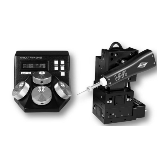
Sutter Instrument TRIO MP-245 Operation Manual (60 pages)
Three-Axis Motorized Micromanipulator System
Brand:
Sutter Instrument
| Category:
Laboratory Equipment
| Size: 3 MB
Table of Contents
Disclaimer
5
Safety Warnings and Precautions
5
Electrical
5
Avoiding Electrical Shock and Fire-Related Injury
5
Electromagnetic Interference
5
Operational
5
Other
6
Handling Micropipettes
6
Table of Contents
7
1 Introduction
11
Structure of the TRIO MP-245 Documentation Package
11
Components of the TRIO MP-245 System
11
Figure 1-1. the TRIO MP-245 System
11
Overview
12
Features
12
Description
12
2 Installation
15
Mounting Instructions
15
Mounting the TRIO MP-245/M to the Stand or Platform
15
Figure 2-1. Side View of TRIO MP-245/M Showing Mounting Adapter Plate and Lock Screws
15
Headstage Mounting
16
Other Accessories
16
Electrical Connections and Initial Operating Instructions
16
Figure 2-2. Mounting the TRIO MP-245/M on the Adapter Plate
16
Roe/Controller Rear Panel Controls and Configuration
17
Power Switch
17
Figure 2-3. Rear of TRIO MP-245 Roe/Controller Cabinet
17
Configuration Switches
18
Switches 1, 2, 3 and 4: Knob Rotation Directionality for Forward (+) Movement
18
Switch 5: Y-Axis Lockout During Homing
18
Figure 2-4. Configuration Switches on Rear of TRIO MP-245 Roe/Controller Unit (Switch Positions Shown Are Factory Defaults)
18
Table 2-1. Configuration Switches 1 - 4: Configuring the Direction of each Axis
18
Table 2-2. Configuring the Homing Y-Movement Lock out
18
Switch 6: Sensor Test (Firmware < V2.2)
19
Switch 6: Sensor Test (Firmware < V2.4)
19
Switch 6: Calibration Homing on Power on (Firmware V2.4)
19
Switch 6: Calibration Homing on Power on (Firmware V2.62)
19
Table 2-3. Configuring the Sensor Test (Firmware < V2.2)
19
Table 2-4. Configuration Switch 6: Configuring the Sensor Test
19
Table 2-5. Configuration Switch 6: Calibration Homing on Power on (Firmware V2.4)
19
Table 2-6. Configuration Switch 6: Configuring Power-On Positional Memory or Calibration
19
Switch 7: PULSE Button Functionality (Firmware V2.4)
20
Switch 7 Reserved (Firmware V2.62)
20
Switch 8: Electromechanical Device Compatibility (Firmware V2.4))
20
Switch 8 Reserved (Firmware V2.62)
20
Switch 9: Y-Axis Travel Length (Firmware V2.4)
20
Table 2-7. Configuration Switch 7: PULSE Button Functionality (FW V2.4)
20
Table 2-8. Configuration Switch 8: Electromechanical Device Compatibility
20
Table 2-9. Configuration Switch 9: Y-Axis Travel Length (Firmware V2.4)
20
Switch 9 Electromechanical Device Compatibility (Firmware V2.62)
21
Switch 10: Length of X Axis (Firmware V2.4)
21
Switch 10: Reserved (Firmware V2.62)
21
Table 2-10. Configuration Switch 9: Electromechanical Device Compatibility (Firmware V2.62)
21
Table 2-11. Configuration Switch 10: Length of X Axis (Firmware V2.4)
21
3 Operations
23
Main Controls and Indicators on the Roe/Controller
23
Display
23
Initial Startup
23
Figure 3-1. LCD Display Showing Startup Screen
23
Figure 3-2. Startup Screen
23
Control Operations
24
Maximum Positive Position Values
24
Setting Position for HOME or WORK
24
Setting the Angle of the Pipette/Headstage Holder
24
Operating the Virtual D Axis
24
Figure 3-3. Factory Default Startup (Home) Position
24
Figure 3-4. Maximum Positive Values
24
Table 3-1. Maximum Positive Position Value of each Axis
24
Moving to the Home Position
25
Moving to the Work Position
25
Figure 3-5. Moving to Home Position (Screen Is Amber While Moving)
25
Figure 3-6. Factory Default Home Position
25
Figure 3-7. Example Home Position Defined and Saved
25
Figure 3-8. Example Work Position
25
Setting Absolute/Relative Coordinates Mode
26
Mode Indications
26
Figure 3-9. Relative Mode
26
Figure 3-10. Relative Mode
26
Figure 3-11. Absolute Mode
26
Speed Control and ROE Knob Movements (SPEED)
27
Movement Knobs Disabling and Lock Mode ([SPEED]/LOCK)
27
Pausing Home Movements (HOME (While Moving to Home))
27
Pausing Work Movements (WORK (While Moving to Work))
27
Pulse Mode and Virtual D-Axis Movement (PULSE)
27
Micropipette/Headstage Exchange
27
Table 3-2. Screen Colors and Modes
27
Figure 3-12. Angled Side View of TRIO MP-245/M to Change Headstage Mount
28
4 External Control
29
General
29
Virtual COM Port (VCP) Serial Port Settings
29
Protocol and Handshaking
29
Table 4-1. USB-VCP Interface Serial Port Settings
29
Command Sequence Formatting
30
Axis Position Command Parameters
30
Microsteps and Microns (Micrometers)
31
Ranges and Bounds
31
Travel Speed
31
Table 4-2. Microns/Microsteps Conversion
31
Table 4-3. Ranges and Bounds
31
Table 4-4. Travel Speeds
31
Commands
32
Get Current Position and Angle ('C' or 'C') Command
32
Move to Controller-Defined HOME Position ('H') Command
32
Move to Controller-Defined WORK Position ('W') Command
32
Table 4-5. Get Current Position and Angle ('C' or 'C') Command
32
Table 4-6. Move to Controller-Defined HOME Position ('H') Command
32
Table 4-7. Move to Controller -Defined WORK Position ('W') Command
32
Move to Specified "Home" Position ('H') Command
33
Move to Specified "Work" Position ('W') Command
33
Move in Straight Line to Specified Position at Specified Speed ('S') Command
33
Table 4-8. Move to Specified "Home" Position ('H') Command
33
Table 4-9. Move to Specified "Work" Position ('W') Command
33
Table 4-10. Straight-Line Move to Specified Position ('S') Command
34
Table 4-11. Straight-Line Move 'S' Command Speeds for MP-245[S]/M-Based Configuration
34
Interrupt Straight-Line Move ('^C') Command
35
Move to Specified X-Axis Position ('X' or 'X') Command
35
Table 4-12. Straight-Line Move 'S' Command Speeds for MP-285/M-Based Configuration
35
Table 4-13. Interrupt a Straight-Line Move in Progress ('^C') Command
35
Move to Specified Y-Axis Position ('Y' or 'Y') Command
36
Move to Specified Z-Axis Position ('Z' or 'Z') Command
36
Table 4-14. Move to Specified X-Axis Position ('X' or 'X') Command
36
Table 4-15. Move to Specified Y-Axis Position ('Y' or 'Y') Command
36
Table 4-16. Move to Specified Z-Axis Position ('Z' or 'Z') Command
36
Setting the Angle ('A') Command
37
Recalibrate ('R') Command
37
Notes
37
Table 4-17. Set the Angle ('A') Command
37
Table 4-18. Recalibrate ('R') Command
37
Table 4-19. Straight-Line Move 'S' Command Speeds for MP-845[S]/M-Based Configuration
40
Table 4-20. Straight-Line Move 'S' Command Speeds for MP-285/M-Based Configuration
41
5 Maintenance
43
6 Reconfiguration
43
Changing the Rotary Knob Functions on the Roe/Controller
43
Figure 6-1. Locations of the Axis Connectors Inside the Roe/Controller
43
Appendix A. Limited Warranty
45
Appendix B. Accessories
46
Appendix C. Technical Specifications
47
Table C-1. TRIO MP-245 Cables and Receptacles/Connectors
48
Appendix D. Quick Reference
49
Manual Operation
49
Configuration
49
Table D-1. Configuration Switches 1 - 5
49
Table D-2. Configuration Switches 6 - 10 (Ver. <2.4)
49
Table D-3. Config. Switches 6 - 10 (Ver. 2.62)
49
External Control
50
Table D-4. Config. Switches 6 - 10 (Ver. 2.4)
50
Table D-5. USB-VCP Interface Serial Port Settings
50
Table D-6. Microns/Microsteps Conversion
51
Table D-7. Ranges and Bounds
51
Table D-8. Travel Speeds
51
Table D-9. TRIO MP-245 External Control Commands
52
Table D-10. Straight-Line Move 'S' Command Speeds for MP-245[S]/M-Based Configuration
55
Table D-11. Straight-Line Move 'S' Command Speeds for MP-285/M-Based Configuration
55
Index
57
Advertisement
Advertisement
Related Products
Sutter Instrument TRIO MP-235
Sutter Instrument MP-225
Sutter Instrument TRIO MP-245A
Sutter Instrument MPC-78
Sutter Instrument MP-225A
Sutter Instrument MP-285
Sutter Instrument MP-285A
Sutter Instrument TRIO MPC-145 Series
Sutter Instrument TRIO MP-845 Series
Sutter Instrument TRIO MPC-145S
Sutter Instrument Categories
Laboratory Equipment
Amplifier
Control Systems
Controller
Work Light
More Sutter Instrument Manuals
Login
Sign In
OR
Sign in with Facebook
Sign in with Google
Upload manual
Upload from disk
Upload from URL