Honeywell TR80 Installation And Operating Manual
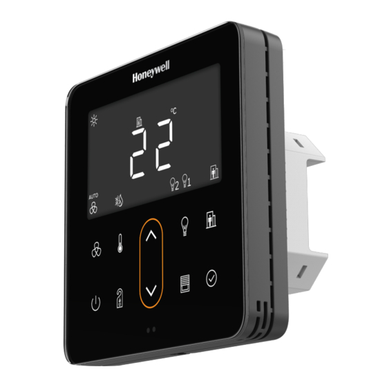
Wall module
Hide thumbs
Also See for TR80:
- Installation and operating manual (78 pages) ,
- Mounting instructions (2 pages)
Table of Contents
Advertisement
Quick Links
Advertisement
Table of Contents

Subscribe to Our Youtube Channel
Related Manuals for Honeywell TR80


Summary of Contents for Honeywell TR80
- Page 1 TR80 WALL MODULE Installation and Operating Guide...
- Page 2 Honeywell International Inc. While this information is presented in good faith and believed to be accurate, Honeywell disclaims the implied warranties of merchantability and fitness for a purpose and makes no express warranties except as may be stated in its written agreement with and for its customer.
- Page 3 Revisions Version Published Changes Comment 07-21 08-07-21 Whole document - New document 08-21 20-08-21 Review comments Implemented - New document TR80 - Installation and Operation Guide...
-
Page 4: Table Of Contents
TABLE OF CONTENT CHAPTER 1 - INTRODUCTION TO TR80 ............1 Introduction..............................1 Dimensions..............................2 Installing theTR80 Wall Module......................2 Before Installation ..........................2 Steps to install TR80 Wall module: ................... 3 Wiring Connections .......................... 6 Wiring Terminals.......................... 7 Powering Up the Wall Module ..................... 7 TR80 LCD Display............................. - Page 5 Dimming control with scene selection.................27 Controlling Blinds ..........................28 DO-NOT-DISTURB / MAKE-UP-ROOM ..................28 Cleaning The Front Glass........................29 CHAPTER 3 - CONFIGURATION OF TR80 ..........30 INTRODUCTION ............................. 30 Entering the configuration mode ....................30 Temporary Commissioning Mode ....................31 Factory Reset ............................31 DEVICE ................................31...
- Page 6 Light Group 2 configuration & control ................51 Light Group 3 configuration & control ................52 Light Group 4 configuration & control ................53 Scene definitions for Power Button ..................53 BLINDS CONTROL..........................54 Blind 1 configuration parameters ..................54 TR80 - Installation and Operation Guide...
- Page 7 List of UI and Access configuration parameters..............63 List of HVAC Configuration Parameters..................65 List of Lighting Configuration Parameters................66 List of Blinds configuration Parameters ..................68 List of Occupancy configuration Parameters .................69 List of Display Values configuration parameters..............70 TR80 - Installation and Operation Guide...
-
Page 8: Chapter 1 - Introduction To Tr80
The user- friendly intuitive display and dedicated 10 capacitive touch keys of the device help to achieve the perfect balance between Energy Efficiency and Comfort. TR80 is an advanced, configurable, connected device with its open industry-standard Mod- bus communication protocol that allows easy integration with several intelligent building controllers in diverse configurations. -
Page 9: Dimensions
Note: All wiring must agree with applicable codes, ordinances and regulations or as specified on installation wiring diagrams. Caution: Improper use can create dangerous situations. For life-safety applications, this device can function only as a secondary or lesser device. TR80 - Installation and Operation Guide... -
Page 10: Steps To Install Tr80 Wall Module
Ensure that you are properly grounded before handling the unit. 1.3.2 Steps to install TR80 Wall module: 1. Switch OFF the power supply before initiating the TR80 installation. 2. Loosen the bottom screw a few turns. TR80 - Installation and Operation Guide... - Page 11 3. Separate front panel and base by pulling out from the bottom, to do the wiring. 4. Pull the power cable and communication cables through the wall box. 5. Connect the wires well according to the wiring diagram. Refer to wiring details. TR80 - Installation and Operation Guide...
- Page 12 6. Fix the base with 2 screws to the wall box. 7. Attach front panel to the base. 8. Tighten the bottom screw, to fix front panel and base. TR80 - Installation and Operation Guide...
-
Page 13: Wiring Connections
9. Switch ON the power supply to start the TR80 wall module. 1.3.3Wiring Connections Caution: Electrical Shock or Equipment Damage Hazard. Can shock individuals or short equipment circuitry. Disconnect power supply before Installation. All wiring must comply with local electrical codes and ordinances or as per below wiring connections. -
Page 14: Wiring Terminals
1.3.4 Powering Up the Wall Module Once the wall module is installed and powered, the unit gets started shows firm- ware version number and goes through the startup sequence to display the ready or protected mode. TR80 - Installation and Operation Guide... -
Page 15: Tr80 Lcd Display
1.4 TR80 LCD Display The LCD of TR80 wall module with all possible segments is as shown below: The following table provide an overview of all available segments of the TR80 wall module with its defined name. Name Segment Description... - Page 16 Heating mode Cooling mode HVAC Mode Auto mode Up-to four lighting groups are supported by TR80 wall module. Indicates if the Lighting groups group is ON or OFF, in setting mode indicates selected group. Indicates device is in unoccupied state.
- Page 17 Micro gram per meter cube. Parts Per Million Parts Per Billion unit for Total Volatile Organic compound (TVOC) measurement. Carbon dioxide Total Volatile Organic compound Indoor Air Quality Parameters Particulate Matter 2.5 Particulate Matter 10 TR80 - Installation and Operation Guide...
-
Page 18: User Interface
1.5 User Interface The TR80 user interface consist of multi segment display and 10 capaci- tive touch keys. The following table provides the information of functionality associated with each key on the keypad. Key symbol Name Description Fan key Used to change the fan speed and mode. -
Page 19: Led Ring Behavior
The LED ring is steady on when there is no active heating or cooling. When any heating or cooling source is active (e.g. valves open), the LED ring will be in 'breath- ing'. The breath frequency is related to active heating or cooling level. TR80 - Installation and Operation Guide... -
Page 20: Specification
± 0.2 °C On-board Humidity sensor accuracy ±3% RH from 20-80%RH Other Specification IP Rating IP20 Terminal Connections Rising cage clamp, Screw terminal Standard and Compliance UKCA RoHS Material of Casing Flame retardant Polycarbonate (PC) TR80 - Installation and Operation Guide... -
Page 21: System Architecture
The Shutter User commands(level and/or Angle) is polled from TR80 by controller and executed via digital outputs. • TR80 Modbus Slave to Room controller on Port 1 and DALI as Modbus Slave to TR80 on Port 2 (Direct Light Control). •... - Page 22 TR80 Modbus Slave to Room controller and DALI64 on Sylk bus connected to Room Controller • In this example TR80 act as Modbus slave to controller and DALI 64 is connected to Sylk port of the controller. User light commands are polled from TR80 by controller and Transmitted to DALI64 over sylk bus for execution.
- Page 23 User light commands are polled from TR80 by controller and executed through digital and analogue outputs of the controller. The Shutter User commands(level and/or Angle) are polled from TR80 by controller and executed via digital outputs. TR80 - Installation and Operation Guide...
-
Page 24: Chapter 2 - Operations
Display shows Setting icon on the screen. To access this mode user need to enter four digit pin. TR80 - Installation and Operation Guide... -
Page 25: Access Level
The device enters the sleep mode, if no action is taken in a defined time span. In this mode screen appears to be black-out. Tap any key on the keypad, to activate the screen. TR80 - Installation and Operation Guide... -
Page 26: Unlocking The Device
Most of the information related to current status is represented by symbols on the screen. To view more information: • to enter monitoring mode • to scroll between available values. Each value will be displayed TR80 - Installation and Operation Guide... -
Page 27: Adjusting Temperature
2.6 Adjusting The Fan Speed to change the fan speed. The settings are slightly different depending on type of fan. Two types of fans are supported by TR80 wall module such as: TR80 - Installation and Operation Guide... -
Page 28: Multi Speed Fans
Setting mode. 2. Tap or , to set the fan speed (OFF, LO, MED, HI). 3. After selecting fan speed tap 4. Tap to exit the mode. TR80 - Installation and Operation Guide... -
Page 29: Ec Fans
In this mode, occupancy status is determined by the user. The procedure to switch between Occupied/ unoccupied mode is as follows: 1. Tap to switch between Occupied/ unoccupied mode. The current active occupied/ unoccupied mode is indicated by occupancy sym- bol on the display. TR80 - Installation and Operation Guide... -
Page 30: Advanced Occupied/ Unoccupied Selection
The display shows unoccupied symbol with scrolling text "STAND BY". Bypass The user has overridden the automatic mode and switched the system to comfort mode temporarily. The display shows occupied symbol with scrolling text "Comfort for ... mins" TR80 - Installation and Operation Guide... -
Page 31: Overriding The Occupancy Mode
Below methods are used to change the HVAC mode such as: • Simple operation : Wall module user determines the HVAC mode • Advanced operation: HVAC mode is determined in the controller. The user can temporarily override the automatically determined mode. TR80 - Installation and Operation Guide... -
Page 32: Selecting Eco Operation
ECO symbol . In ECO operation, your system consumes less energy. 2.10 Controlling Lights TR80 allows control of up to 4 lighting groups. The procedur to select group is as follows: 1. Tap , to enter lighting mode. -
Page 33: Basic On/Off Control
When dimming down, the adjustment may stop at a preset minimum level. Keep the down key pressed, or release and re-tap it, to turn the light group completely off. • to switch between OFF and last selected level. TR80 - Installation and Operation Guide... -
Page 34: On/Off Control With Scene Selection
The display shows current (or last selected) light level as percentage and last selected scene number. • Short-tap to switch between and activate preset scenes • Long-press to dim the lights up or down • •Use the to switch between OFF and last selected level. TR80 - Installation and Operation Guide... -
Page 35: Controlling Blinds
A hotel guest can activate Do-not-Disturb or Make-up-Room functions by tapping the DnD/MuR Key. The procedure to switch in DnD / MuR mode is as follows: 1. Tap , to select DnD / MuR / none (depending on the selected configuration). TR80 - Installation and Operation Guide... -
Page 36: Cleaning The Front Glass
LCD shows make-up-room symbol blinking, lock symbol on, and a countdown in seconds. The default countdown is 60 seconds. Cleaning mode exits auto- matically after countdown. 2. Press key together for three seconds to exit the cleaning mode. TR80 - Installation and Operation Guide... -
Page 37: Chapter 3 - Configuration Of Tr80
CONFIGURATION OF TR80 3.1 INTRODUCTION This chapter provides descriptions for all Modbus registers and configuration parameters that can be used to adopt the TR80 to specific requirements. The information is provided in tables, showing: • Modbus register type (Coil / Input / Holding) •... -
Page 38: Temporary Commissioning Mode
3.3 Temporary Commissioning Mode User can set TR80 in a temporary commissioning mode, by setting time in parameter 17. • The sleep mode will not be activated on timeout. The display will remain on. • The protected mode will not be activated on timeout. The device will remain unlocked. -
Page 39: Device Information
0-255 Device Type is a fixed number used to identify the device as Honeywell TR80 Modbus Wall Module. The Firmware version consists of 4 parts as detailed below. The four parts are encoded in 2registers. In each register, the MSB 8 bits encode the first two parts and the LSB 8 bits encode the last two parts. -
Page 40: Communication
3. 6. 2 Port 2 configuration Port 2 on the TR80 wall module has two functions. It can act as a repeater between a master controller and a downstream DALI64 sensor. Secondly, it can send basic light level and scene commands of the user directly to a DALI64MOD sensor. -
Page 41: General Monitoring Registers
Bit0: Setpoint changed from the default Bit1: Fan speed is overridden (not auto) Override Input 30005 bitwise Bit2: HVAC mode overridden status Bit3: {reserved} Bit4: Occupancy overridden Bit5: DnD active Bit6: MuR active TR80 - Installation and Operation Guide... -
Page 42: What Has Changed
It is important to note that this register automatically returns to the default value of 0 as soon as it is read by the master controller. There is no need for the master to reset it. TR80 - Installation and Operation Guide... -
Page 43: Active Display Mode
2011 42012 sensor 4: 2-10 Vdc type 5: Raw Ohms 6: NTC10K 7: NTC20K On-board sensor -10.0 … +10.0 Holding 2012 42013 temp offset On-board sensor -10 … +10 Holding 2013 42014 humidity offset TR80 - Installation and Operation Guide... -
Page 44: Monitoring
Temperature values on Modbus are always in degrees Celsius, even if the user has selected Fahrenheit for display. 3.9 DO-NOT-DISTURB & MAKE-UP-ROOM Do-not-Disturb and/ Make-Up-Room functions can be enabled individually. The button on the TR80 will be enabled only if at least one of these functions are enabled. Register Relative Absolute... -
Page 45: Cleaning Mode
Default Name Type Range type Address Address parameter value Ring 0-100% 100% Holding 2104 42105 brightness Ring brightness Holding 2105 42106 0-100% in sleep mode Ring Holding 1100 41101 RGB565 0-65535 0 (Auto) colour TR80 - Installation and Operation Guide... -
Page 46: Temperature Display Configuration
1: °F (user can Holding 2108 42109 enum change change) option 2: °C (fixed) 3: °F (fixed) It is possible to disable temperature unit change on the wall module and have it fixed in Celsius or Fahrenheit. TR80 - Installation and Operation Guide... -
Page 47: Lcd Symbols
Relative Absolute Default Name Type Range type Address Address value 0: none 1: "Fan Off" 2: “Clg/Htg Off” Holding 1106 41107 Text override enum 3: "Window Open" 4: "Condensation" 5: "Fire" 6: "Service required" TR80 - Installation and Operation Guide... -
Page 48: Power Button Functions
• Scene settings for lights on & off: If a DALI64 sensor is on port 2, the TR80 can turn the lights on/off directly without involving the master controller. It will do that by sending ‘recall scene’... -
Page 49: User Access Control And Timeouts
DALI side to turn the lights fully off or fully on. These settings are detailed in section 3.11.6. • If a scene number is not set for Lights On or Lights Off functions, TR80 will send absolute light level commands (100% / 0%) instead. Required master controller logic: •... -
Page 50: Hvac
3. 12. 1 Temperature setting The TR80 can operate in absolute or relative setpoint mode. In relative setpoint mode, the user does not see the absolute setpoint, but has the option to shift it up or down, typically by +/-5 degrees. -
Page 51: Fan Speed Control
Bit 1: Display type for single-stage fan (0: 1 bar, 1: 3 bars) 3. 12. 3 HVAC mode selection TR80 allows two different Hvac mode selection options: simple or advanced. In simple mode, the occupancy button simply and directly switches between available modes (heat- ing/cooling/fan/only…) similarly to a basic A/C unit. - Page 52 • BB (bits 9-8): Heating outputs status • CC (bits 11-10): Cooling outputs status • D (bit 12): fan output status • Bits 2..0: • - 0: heat & cool not available (grey ring) TR80 - Installation and Operation Guide...
-
Page 53: Occupancy
- 3096: All cool outputs on (fast breath) • Bit 12: Fan output on (medium breath - only if green) 3.13 OCCUPANCY Occupancy mode selection on the TR80 can go beyond simple occupied/unoccupied states. Following occupancy states are possible: • •... -
Page 54: Occupancy Control
0: unknown 1: not used 2: occupied Effective 3: off Input 30501 enum Occupancy Mode 4: holiday 5: unoccupied 6: standby 7: bypass Occupancy 0: not overriden Input 30502 enum Override Status 1: overriden TR80 - Installation and Operation Guide... -
Page 55: Holiday & Bypass Overrides
Allowed overrides bit4: Allow override to Holding 2506 42507 from STANDBY HOLIDAY bit5: Allow override to UNOCC bit6: Allow override to Allowed overrides Holding 2507 41508 STANDBY from OCC bit7: Allow override to BYPASS TR80 - Installation and Operation Guide... -
Page 56: Auto-Reset Of Occupancy Override
Occupied, Holiday and Bypass From OCCUPIED Unoccupied, Holiday and Bypass 3. 13. 5 Auto-reset of occupancy override The TR80 can be configured to automatically cancel a user occupancy override when the mas- ter occupancy mode changes (holding register 1500). Register Relative... -
Page 57: Light Group 1 Configuration
This info typically comes from the DALI64MOD sensor. If the DALI64 sensor is connected to port 2, the TR80 wall module will read the ‘Group Light State’ directly, without any dependency on a master controller. If DALI64 sensor is connected on port 1 (or a different lighting control system is employed) the master con- troller will need to provide this information to the wall module. -
Page 58: Light Group 1 Control
Level’ and ‘LastScene’ information is missing, the user setting will start from 50% and scene 1. If the DALI64 sensor is connected to port 2, the TR80 wall module will read the ‘Last Level’ and ‘Last Scene’ directly, without any dependency on a master controller. If DALI64 sensor is con- nected on port 1 (or a different lighting control system is employed) the master controller will need to provide this information to the wall module. -
Page 59: Light Group 3 Configuration & Control
Light Group 3 last level 255: unknown) 0-15 Holding 1305 41306 Light Group 3 last scene 255: unknown) Input 30305 Light Group 3 new level 0-100% 32767 Input 30306 Light Group 3 new scene 0-15 32767 TR80 - Installation and Operation Guide... -
Page 60: Light Group 4 Configuration & Control
108/109), the wall module will need to know what scenes to recall for that purpose. Set to zero if no such scene is configured on the DALI side. If set to zero, TR80 will send absolute light level commands (0% / 100%) to turn lights off / on. -
Page 61: Blinds Control
3.15 BLINDS CONTROL TR80 can control up to 2 blinds, curtains or shutters. General blind parameters are as shown below. Register Relative Absolute Config Default Name Unit Range type Address Address parameter value Blind Group Holding 2400 42401 0…2 Count... -
Page 62: Blind 1 Control Parameters
° -180°…180° +80° angle The Blind 2 control parameters are as shown below. Register Relative Absolute Default Name Unit Range type Address Address value 0-100% Holding 1402 41403 Blind 2 current position (255: unknown) TR80 - Installation and Operation Guide... -
Page 63: Display Values
-180…+180° 32767 3.16 DISPLAY VALUES In addition to the operationally required ones, TR80 can display several additional values for user information. The master makes these values available to the wall module by writ- ing to relevant registers. For these registers, the default value is 32767 (hex 7FFF) representing an invalid value. -
Page 64: Custom User Defined Parameter Unit
/ and space are supported. The ‘Attributes’ register is bitwise interpreted as follows: Bit0: scale 0: scale = 1 1: scale = 0.1 Bits 1&2: basic symbols 00: none 01: Indoor icon 10: Set icon TR80 - Installation and Operation Guide... -
Page 65: Configuration
'Display Values Receive Timeout', that value is considered stale and dropped from the list to be displayed, until a fresh value is received again. This function can be disabled by set- ting the parameter to 0. TR80 - Installation and Operation Guide... - Page 66 15: Energy in kwh 16: Room Number 17: HVAC Override Status 18: Reserved1 19: Reserved2 20: Reserved3 21: Reserved4 22: Custom parameter unit Register 1 23: Custom parameter unit Register 2 24: Reserved5 25: Reserved6 TR80 - Installation and Operation Guide...
-
Page 67: Chapter A - Troubleshooting
Contact Customer care External sensor fault Check wiring and replace sensor if faulty Modbus loss of comms Check wiring and master controller Port 2 timeout fault Check wiring and DALI64 sensor on port 2 TR80 - Installation and Operation Guide... -
Page 68: Chapter B - Configuration Parameters
LCD backlight brightness in percent Port2 Parity Resets some settings to default values Port2 StopBits 0-9999 0x7FFF Room Number Port2 Response Timeout Dali64 sensor slave 0-247 0 = No DALI sensor on port 2, no address repeater function TR80 - Installation and Operation Guide... - Page 69 3: Dnd/Mur enable" Reset to defaults bool Resets some settings to default values. Primarily modbus comms settings. Exact list to be compiled later Note: Config from MAster controller details will be available in Master Controller documents. TR80 - Installation and Operation Guide...
-
Page 70: List Of Ui And Access Configuration Parameters
1: Dark Mode READY mode 2: Sleep Mode 3:SwitchLightsOnOff Toggle 4: SwitchLightsOn 5: SwitchLightsOff 6: Hello/Goodbye toggle 7: Hello 8: Goodbye Power Button long enum same as above Not implemented yet press function in READY mode TR80 - Installation and Operation Guide... - Page 71 0000…9999 Only used if User Access Protection = secure Config menu Pin 0000…9999 4663 'HONE' on keypad Timeout to lock seconds 0…300 seconds 15 sec If value is 0, timeout will be status disabled. TR80 - Installation and Operation Guide...
-
Page 72: List Of Hvac Configuration Parameters
Bit 1: Display of 1-stage speed indication & AUTO symbol fan (0: 1 bar, 1: 3 bars) Bit 2-16: reserved HvacMode enum 0: disabled SelectionTy 1: simple 2: advanced TR80 - Installation and Operation Guide... -
Page 73: List Of Lighting Configuration Parameters
Light Group 2 max 0…100% 100% level Light Group 2 Max 0-16 0 = scene selection disabled Scene No Light Group 3 type enum 0: on-off / 1: dimmable Light Group 3 min 0…100% level TR80 - Installation and Operation Guide... - Page 74 Light Group 4 type enum 0: on-off / 1: dimmable Light Group 4 min 0…100% level Light Group 4 max 0…100% 100% level Light Group 4 Max 0-16 0 = scene selection disabled Scene No TR80 - Installation and Operation Guide...
-
Page 75: List Of Blinds Configuration Parameters
(0: reverse, 1: direct) Blind 2 position min 0…100% Blind 2 position max 0…100% Blind 2 angle min signed int (°) -180°…180° -80° Blind 2 angle max signed int (°) -180°…180° +80° TR80 - Installation and Operation Guide... -
Page 76: List Of Occupancy Configuration Parameters
Allow override to - UNOCC BYPASS - BYPASS Allowed bitmap 144: HOL & overrides from BYPASS UNOCC Allowed bitmap 148: OCC, HOL overrides from & BYPS STANDBY Allowed bitmap 176: UNOCC, overrides from HOL & BYPS TR80 - Installation and Operation Guide... -
Page 77: List Of Display Values Configuration Parameters
List of Display Values configuration parameters Config Range parameter Name Type/ Unit Default Notes (min-Max) number Home display enum See below parameter Display Values mins 1…60 Receive Timeout TVOC unit enum 0: ug/m3 1: mg/m3 2: ppm 3. ppb TR80 - Installation and Operation Guide... - Page 78 Honeywell Building Technologies 1985 Douglas Drive North Golden Valley, MN 55422 customer.honeywell.com Honeywell Building Control ™ 31-00482M-01 09/21...
Need help?
Do you have a question about the TR80 and is the answer not in the manual?
Questions and answers