Table of Contents
Advertisement
Available languages
Available languages
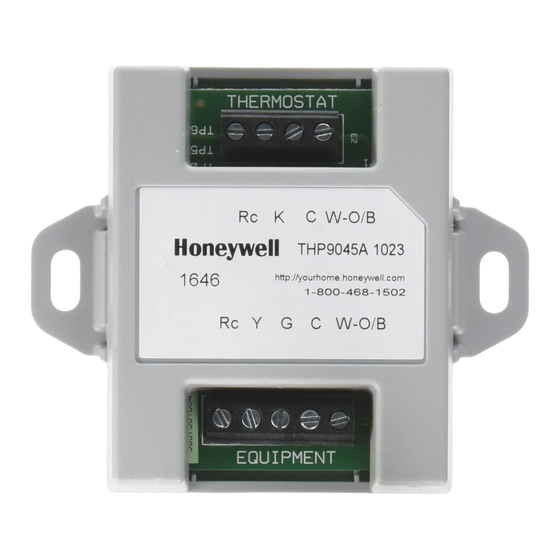
WIRESAVER
THERMOSTAT
Rc K C
Honeywell
Rc Y G C
EQUIPMENT
APPLICATION
The THP9045 Wiring Module is designed to be used with
applicable thermostats in which a 24V common is
required and there are not enough wires. The K terminal
on the thermostat can be used to operate both the fan
and compressor on a single wire, and the module is
designed to receive the signal from the K terminal, split
that signal and re-route it to operate the compressor,
and/or fan for normal operation.
Use with the following thermostats:
— THX9321R
— THX9321R5000
— THX9321R1008
— TH8320UP1003
— T5060F7088
W-O/B
THP9045A
W-O/B
M31301A
Installation INSTRUCTIONS
FEATURES
• Can be used when a common wire is required.
• Mounts easily on or near HVAC equipment.
INSTALLATION
1. The THP9045 Wiring Module can be equipment- or
wall-mounted in any orientation or as dictated by
the surroundings.
2. Precise leveling of the THP9045 module is not
required.
3. Identify the four wires in the wall and connect to the
R, C, W, and K terminals on the thermostat.
4. Wire the K terminal on the thermostat to the K ter-
minal on the THP9045 module.
5. Wire the R and C terminals on the thermostat to
the R (power) and C (common) terminals on the
THP9045 module and equipment.
6. Wire the W terminal from the thermostat to the W
(heat relay) terminal on the HVAC equipment.
7. Wire the Y and G terminals on the Module to the Y
(Compressor Relay) and G (Fan Relay) terminals
on the HVAC equipment.
TERMINALS
R
24V
C
24V Common
Y
Cooling relay
G
Fan relay
K
Communication
Place Bar Code Here
69-2065EFS-07
Advertisement
Table of Contents

Related Manuals for Honeywell THP9045


Summary of Contents for Honeywell THP9045
- Page 1 (heat relay) terminal on the HVAC equipment. 7. Wire the Y and G terminals on the Module to the Y The THP9045 Wiring Module is designed to be used with (Compressor Relay) and G (Fan Relay) terminals applicable thermostats in which a 24V common is on the HVAC equipment.
- Page 2 THP9045 WIRING MODULE THX9321R SUBBASE WIRESAVER CONVENTIONAL USED USED Rc K C W-O/B AUX/E Honeywell THP9045A Rc Y G C W-O/B USED USED USED FURNACE HEAT PUMP M31302A Fig. 1. Example wiring diagram for 1H/1C conventional application. THX9321R SUBBASE WIRESAVER...
- Page 3 THP9045 WIRING MODULE THX9321R SUBBASE WIRESAVER CONVENTIONAL USED USED AUX/E Rc K C W-O/B Honeywell THP9045A Rc Y G C W-O/B USED USED USED HEAT PUMP G C O Y2 W2 AIR HANDLER M31306A Fig. 3. Example wiring diagram for a 2H/2C conventional application.
- Page 4 Automation and Control Solutions Honeywell International Inc. 1985 Douglas Drive North Golden Valley, MN 55422 Honeywell Limited-Honeywell Limitée 35 Dynamic Drive ® U.S. Registered Trademark Toronto, Ontario M1V 4Z9 © 2010 Honeywell International Inc. 69-2065EFS—07 M.S. Rev. 12-10 http://customer.honeywell.com Printed in U.S.A.
- Page 5 Rc K C W-O/B INSTALLATION Honeywell THP9045A 1. Le module THP9045 peut être installé sur le Rc Y G C W-O/B système de CVCA ou sur un mur. Le sens de montage n'a pas d'importance et dépend l'emplacement. 2. Il n'est pas nécessaire d'installer le module THP9045 de niveau.
- Page 6 MODULE DE CÂBLAGE THP9045 PROTECTEUR PLAQUE DE RACCORDEMENT THX9321R DE FIL CONVENTIONAL USED USED Rc K C W-O/B AUX/E Honeywell THP9045A W-O/B Rc Y G C USED USED USED APPAREIL DE CHAUFFAGE HEAT PUMP MF31302A Fig. 1. Exemple de schéma de câblage pour une application conventionnelle à...
- Page 7 MODULE DE CÂBLAGE THP9045 PROTECTEUR PLAQUE DE RACCORDEMENT THX9321R DE FIL CONVENTIONAL USED USED AUX/E Rc K C W-O/B Honeywell THP9045A Rc Y G C W-O/B USED USED USED HEAT PUMP G C O Y2 W2 SECTION DE TRAITEMENT D’AIR MF31306A Fig.
- Page 8 MODULE DE CÂBLAGE THP9045 PLAQUE DE RACCORDEMENT THX9321R CONVENTIONAL PROTECTEUR DE FIL USED USED AUX/E Rc K C W-O/B Honeywell THP9045A Rc Y G C W-O/B USED USED USED HEAT PUMP FAIRE CORRESPONDRE NORMALEMENT LES FILS DE LA THERMOPOMPE À LA SECTION DE TRAITEMENT DE L’AIR.
- Page 9 5. Cablee los terminales R y C en el termostato a los terminales R (energía) y C (común) en el módulo El módulo de cableado THP9045 está diseñado para ser THP9045 y el equipo. utilizado con los termostatos aplicables en los cuales se 6.
- Page 10 MÓDULO DE CABLEADO THP9045 PROTECTOR SUBBASE THX9321R DE CABLE CONVENTIONAL USED USED Rc K C W-O/B AUX/E Honeywell THP9045A Rc Y G C W-O/B USED USED USED SISTEMA DE CALEFACCIÓN HEAT PUMP MS31302A Fig. 1. Ejemplo del diagrama de cableado para la aplicación convencional de 1 etapa de calefacción/1 etapa de refrigeración (1H/1C).
- Page 11 MÓDULO DE CABLEADO THP9045 PROTECTOR SUBBASE THX9321R DE CABLE CONVENTIONAL USED USED AUX/E Rc K C W-O/B Honeywell THP9045A Rc Y G C W-O/B USED USED USED HEAT PUMP G C O Y2 W2 CONTROLADOR DE AIRE MS31306A Fig. 3. Ejemplo del diagrama de cableado para la aplicación convencional de 2 etapas de calefacción/2 etapas de refrigeración (2H/2C).
- Page 12 Honeywell International Inc. 1985 Douglas Drive North Golden Valley, MN 55422 Honeywell Limited-Honeywell Limitée ® Marca Registrada en los EE. UU. 35, Dynamic Drive © 2010 Honeywell International Inc. todos Toronto, Ontario M1V 4Z9 Los Derechos Reservados 69-2065EFS—07 M.S. Rev. 12-10 http://customer.honeywell.com...
Need help?
Do you have a question about the THP9045 and is the answer not in the manual?
Questions and answers
how to light the pilot light model thp9045
The Honeywell THP9045 is a wiring module, not a device with a pilot light. It does not have a pilot light to ignite.
This answer is automatically generated
how to light pilotlite
The Honeywell THP9045 is not a gas appliance and does not have a pilot light. It is a wiring module used for thermostat installations. Therefore, lighting a pilot light does not apply to this device.
This answer is automatically generated