Table of Contents
Advertisement
Quick Links
PRODUCT INFORMATION
DES CRIPTION
Thankyou for purchasing Hollyland wireless HD v ideo transmission system. Theproduct uses currently
newest encode, decode and 5G wireless transmission technologies.And can achieve ultra-low latency video
transmission. It transmits over 600FTwith a clean line o f sight (LOS), supportsup to 1080P 60Hz resolution,
and in the end achieves Full HD HDM I v ideo transmission.
KEY FEATUR ES
200m Transmission Range
Less than 0.1s Latency
HDM I Input &HDMI Loop Out, Dual HDM I Output
Mounting Batteries for Both the Transmitter and Receiver
6~16V DC Po wer Input
1 Transmitter withMultiple Receivers
Smart Terminal Monitoring
Smart ChannelSelecting
USB Firmware Upgrade
OLED Display
Stable & Reliable Industrial Metal Case
APPLICATIONS
Filmmaking
Live Broadcasting
Sports Activities
Education Record ing
Wedding Ceremonies
Corporate Events
PACKING LIS T
1
Advertisement
Table of Contents

Subscribe to Our Youtube Channel
Related Manuals for Hollyland CH12


Summary of Contents for Hollyland CH12
- Page 1 PRODUCT INFORMATION DES CRIPTION Thankyou for purchasing Hollyland wireless HD v ideo transmission system. Theproduct uses currently newest encode, decode and 5G wireless transmission technologies.And can achieve ultra-low latency video transmission. It transmits over 600FTwith a clean line o f sight (LOS), supportsup to 1080P 60Hz resolution, and in the end achieves Full HD HDM I v ideo transmission.
- Page 2 ① Transmitter ② Receiver ③ Antenna ④ Quick Gu ide x1 ⑤ Cold Shoe ⑥ Expansion Accessory x1 ⑦ DC Adapter x1 ⑧ Type-C Converter x1...
- Page 3 STANDARD SETUP This wireless HD video transmission system uses the latest wireless communication technology, andtransmits ultra-low latency HD v ideo transmission.The transmitter supports HDMI Input and HDMI loop out, while the receiver supports dual HDMI output. It is equipped with OLED display screen and supports Smart Terminal Monitoring.
-
Page 4: Product Interfaces
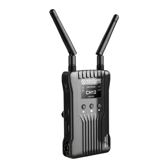
PRODUCT INTERFACES A Transmitter B Receiver ① Antenna Interface ① Antenna Interface ② HDM I Input ② HDM I Output ③ HDM I Loop Out ③ DC Input ④ DC Input ④ OLED Display ⑤ OLED Display ⑤ Button Down ⑥... -
Page 5: Installation
INSTALLATION ① Install the antenna as demonstrated ② Mount and fixedthe transmitter&receiver ③ Connect to a power supply ④ Turn on the device... -
Page 6: Oled Display
OLED DISPLAY A Transmitter B Receiver ① Device ID ① Device ID ② Scene Mode ② Scene Mode ③ USBDisk Detection Display ③ USBDisk Detection Display ④ BatteryStatus ④ Battery Status ⑤ Signal Strength ⑤ Signal Strength ⑥ ReceiverNu mber ⑥... -
Page 7: Channel Change
The black and bold text on white background means that it is the DFS channel, wh ile the white text on the black background is the non-DFS channel. When the device detects the USB d isk connected, the USB d isk detection display lights up. When the voltage is too low, the low battery alarm will be triggered and the icon will flash slowly . - Page 8 Press“OK” button for about 3 seconds, entering into the root menu interface which includes channel scan, system setting, version information options. Select “CHA NNEL SCAN”, then click “OK” button, the device will scan and detect the current frequency environment, available “√”, unavailable “╳”. Select “SYSTEM SETTING”, then click “OK”...
- Page 9 HDM I Loop Out (Type A Female) HDM I Output 2 (Type A Female) 2 Antenna Interfaces (RP-SMA 2 Antenna Interfaces (RP-SMA Male) Male) DC Input, Type-C USB; DC Input, Type-C USB; Supply Power 6~16V DC 6~16V DC Range Power <10W <6W Consumption...
-
Page 10: Fcc Warning
APP Connecting Issues For Android systems, pleasemake sureto selectNon DFS channel. Please check the nu mber of APP devices. One transmitter supportsmaximu m 1receiver and4 App monitoring devices, or 1 transmitter with maximu m2 receivers, withno APP monitoring. FCC WARNING This device comp lies with part 15 o f the FCC Rules.
Need help?
Do you have a question about the CH12 and is the answer not in the manual?
Questions and answers